Electrical connector
Mueller , et al. November 10, 2
U.S. patent number D901,400 [Application Number D/616,375] was granted by the patent office on 2020-11-10 for electrical connector. This patent grant is currently assigned to PHOENIX CONTACT GMBH & CO. KG. The grantee listed for this patent is Phoenix Contact GmbH & Co. KG. Invention is credited to Peter Berg, Thorsten Gelhaus, Thorsten Heil, Jens Leinhart, Gerwin Mueller, Silvester Paul, Steffen Pfoertner, Andrei Siegel, Michael Tegt, Oliver Thoren, Martin Wetter.


View All Diagrams
| United States Patent | D901,400 |
| Mueller , et al. | November 10, 2020 |
Electrical connector
Claims
CLAIM The ornamental design for an electrical connector, as shown and described.
| Inventors: | Mueller; Gerwin (Kiel, DE), Berg; Peter (Schlangen, DE), Tegt; Michael (Lemgo, DE), Thoren; Oliver (Schieder-Schwalenberg, DE), Siegel; Andrei (Paderborn, DE), Pfoertner; Steffen (Spring, DE), Paul; Silvester (Detmold, DE), Wetter; Martin (Detmold, DE), Heil; Thorsten (Bad Salzuflen, DE), Gelhaus; Thorsten (Hameln, DE), Leinhart; Jens (Steinheim, DE) | ||||||||||
|---|---|---|---|---|---|---|---|---|---|---|---|
| Applicant: |
|
||||||||||
| Assignee: | PHOENIX CONTACT GMBH & CO.
KG (Blomberg, DE) |
||||||||||
| Appl. No.: | D/616,375 | ||||||||||
| Filed: | September 6, 2017 |
Foreign Application Priority Data
| Mar 7, 2017 [DE] | 40 2017 100 283 | |||
| Current U.S. Class: | D13/159 |
| Current International Class: | 1303 |
| Field of Search: | ;D13/110,112,118,123,133,154,158-162.1,169-171,173,175,178,184,199 |
References Cited [Referenced By]
U.S. Patent Documents
| D616834 | June 2010 | Heggemann |
| D626516 | November 2010 | Hakemeyer |
| D638804 | May 2011 | Giordanino |
| 8647157 | February 2014 | Gan |
| D700897 | March 2014 | Min |
| D732483 | June 2015 | Min |
| D792352 | July 2017 | Masaki |
| D811349 | February 2018 | Huettemeier |
| 2005/0079753 | April 2005 | Wilinski |
| 2007/0049129 | March 2007 | Pollmann |
| 2009/0157937 | June 2009 | Kuschke |
| 2010/0146167 | June 2010 | Rasche |
| 2011/0059658 | March 2011 | Eisert |
| 2011/0062011 | March 2011 | Pollmann |
| 2012/0071038 | March 2012 | Ondusko |
| 2012/0252262 | October 2012 | Reibke |
| 2013/0052884 | February 2013 | Hanses |
| 2015/0228435 | August 2015 | Hudetz |
| 2016/0240940 | August 2016 | Wu |
| 2017/0162955 | June 2017 | Berg |
| 2019/0288411 | September 2019 | Masaki |
| 2019/0288412 | September 2019 | Masaki |
| 2019/0288414 | September 2019 | Masaki |
Assistant Examiner: Gingrich; Shawn T
Attorney, Agent or Firm: Leydig, Voit & Mayer, Ltd.
Description
The patent or application file contains at least one drawing executed in color. Copies of this patent or patent application publication with color drawing(s) will be provided by the Office upon request and payment of the necessary fee.
FIG. 1 is a top left front perspective view of a first embodiment of the electrical connector showing our new design;
FIG. 2 is a top plan view thereof;
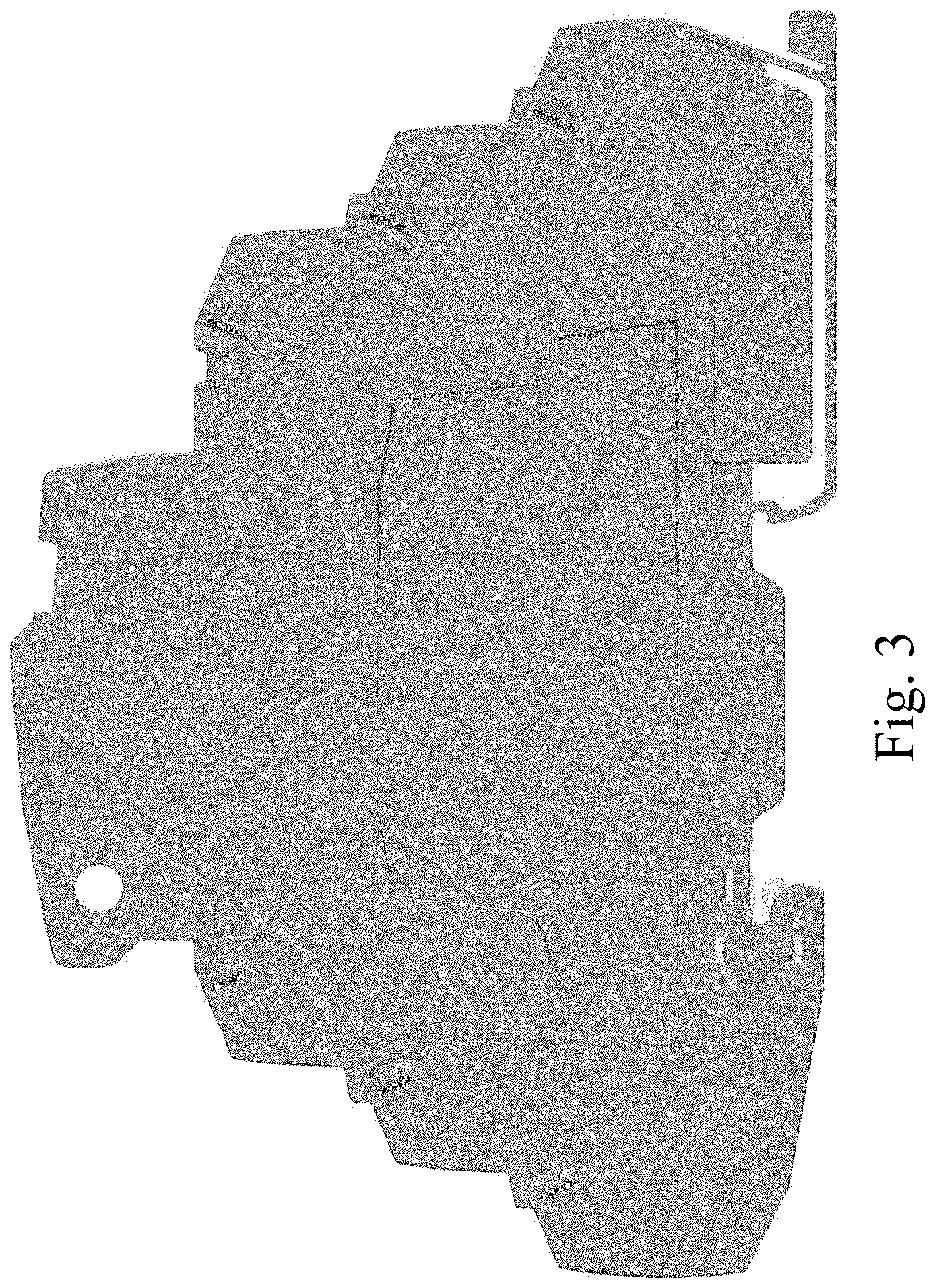
FIG. 3 is a left side elevational view thereof;
FIG. 4 is a front elevational view thereof;
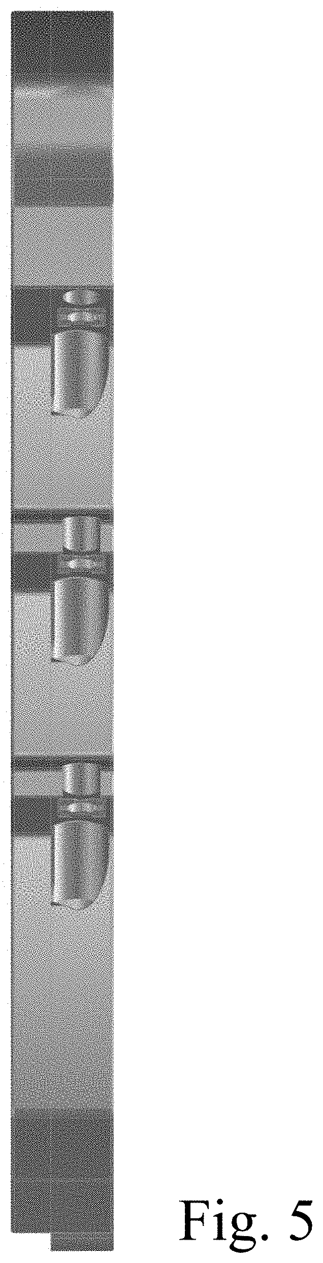
FIG. 5 is a rear elevational view thereof;
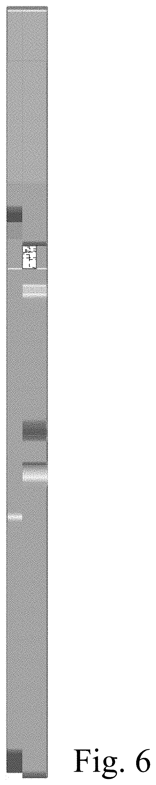
FIG. 6 is a bottom plan view thereof;
FIG. 7 is a right side elevational view thereof; and
FIG. 8 is a top left front perspective view of a second embodiment of the electrical connector showing our new design;
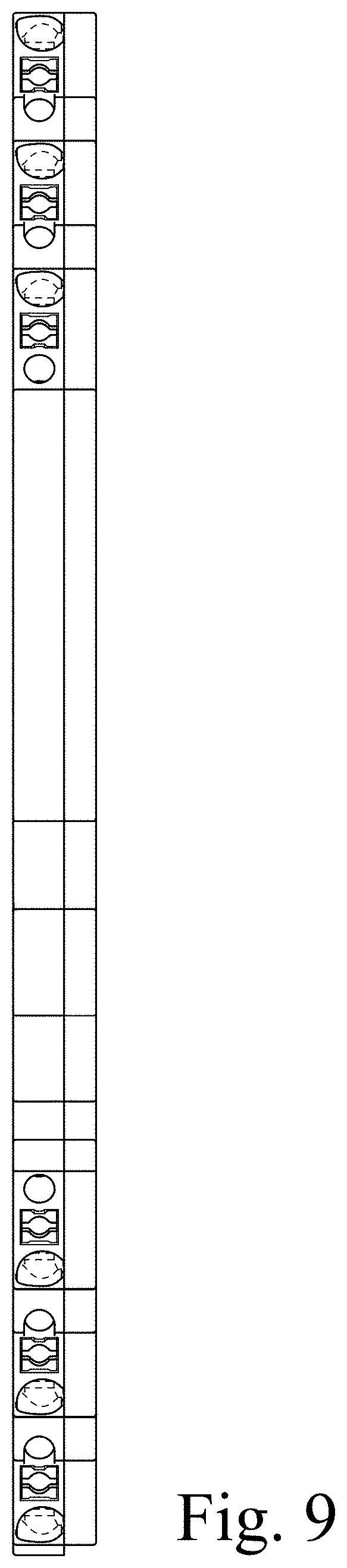
FIG. 9 is a top plan view thereof;
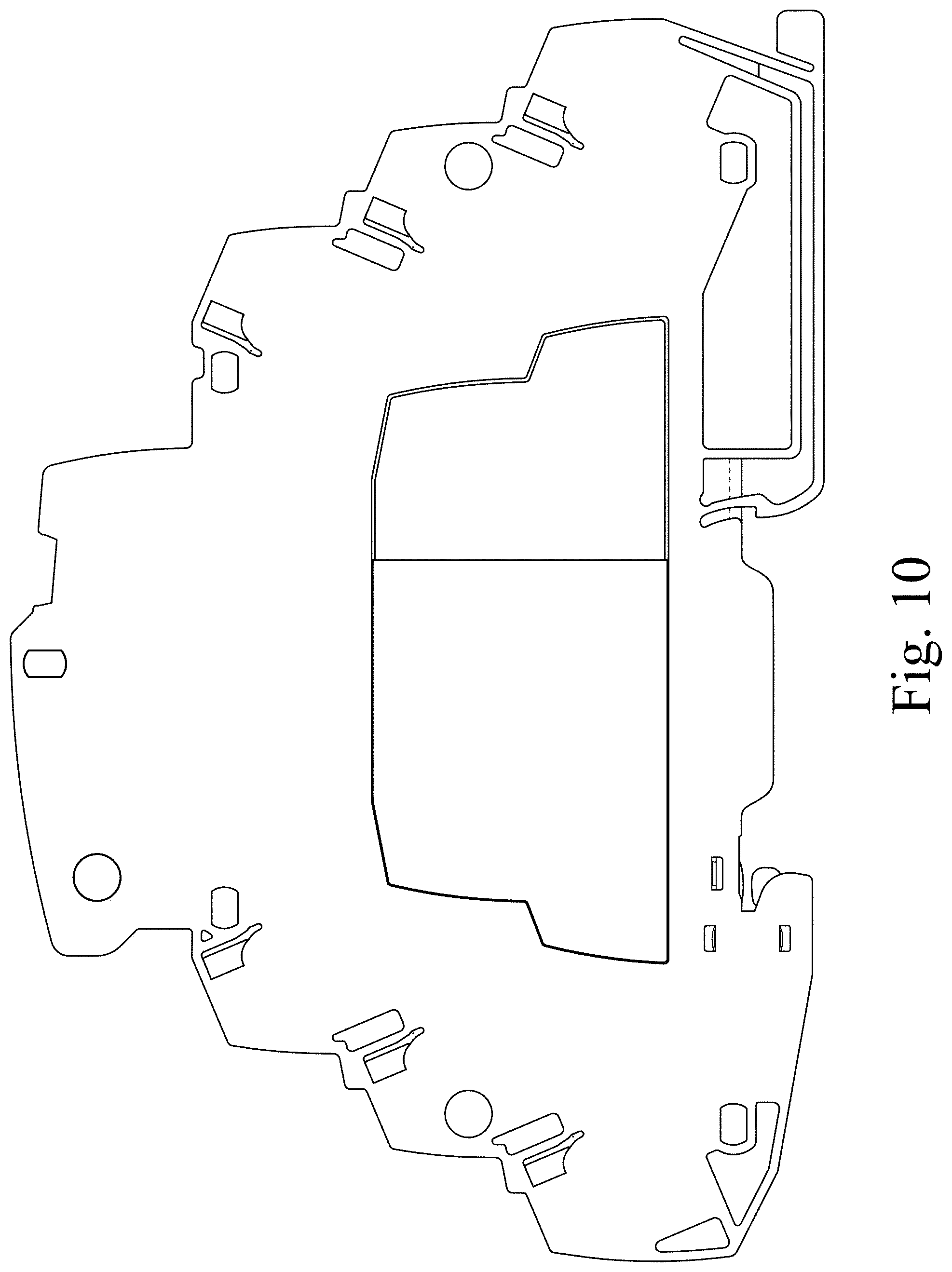
FIG. 10 is a left side elevational view thereof;
FIG. 11 is a front elevational view thereof;
FIG. 12 is a rear elevational view thereof;
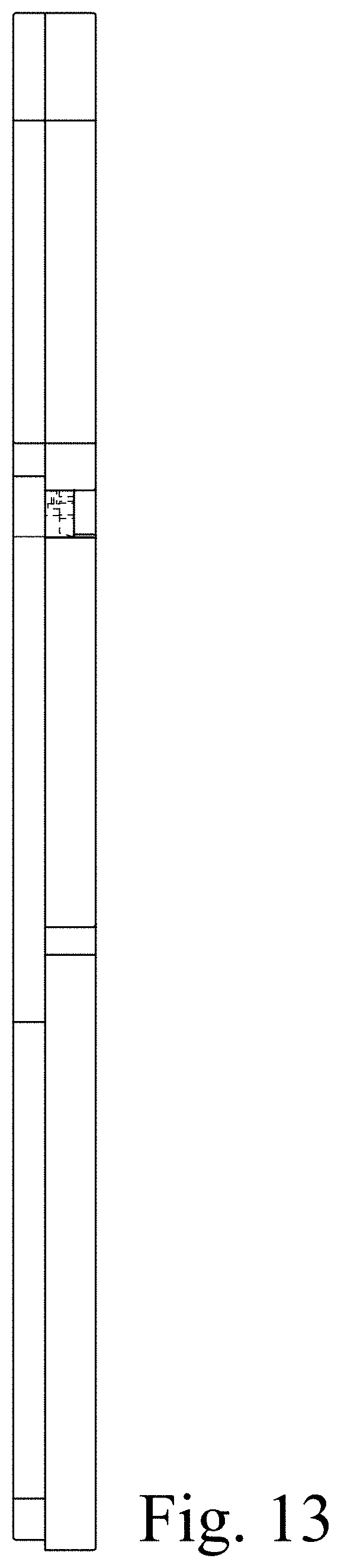
FIG. 13 is a bottom plan view thereof; and,
FIG. 14 is a right side elevation view thereof.
The broken lines in the drawings illustrate portions of the electrical connector housing that form no part of the claimed design. The broken lines in FIGS. 7 and 14. immediately adjacent to the solid lines, are boundary lines, and the portions within the boundary lines form no part of the claimed design.
* * * * *
D00000
D00001
D00002
D00003
D00004
D00005
D00006
D00007
D00008
D00009
D00010
D00011
D00012

D00013
D00014

XML
uspto.report is an independent third-party trademark research tool that is not affiliated, endorsed, or sponsored by the United States Patent and Trademark Office (USPTO) or any other governmental organization. The information provided by uspto.report is based on publicly available data at the time of writing and is intended for informational purposes only.
While we strive to provide accurate and up-to-date information, we do not guarantee the accuracy, completeness, reliability, or suitability of the information displayed on this site. The use of this site is at your own risk. Any reliance you place on such information is therefore strictly at your own risk.
All official trademark data, including owner information, should be verified by visiting the official USPTO website at www.uspto.gov. This site is not intended to replace professional legal advice and should not be used as a substitute for consulting with a legal professional who is knowledgeable about trademark law.