Flow passage contours for a hydraulic manifold for actuator control with dual solenoids
Mellor , et al. November 3, 2
U.S. patent number D900,899 [Application Number D/690,637] was granted by the patent office on 2020-11-03 for flow passage contours for a hydraulic manifold for actuator control with dual solenoids. This patent grant is currently assigned to THE BOEING COMPANY. The grantee listed for this patent is The Boeing Company. Invention is credited to Mitchell L. R. Mellor, Jonathan B. Wallace.


| United States Patent | D900,899 |
| Mellor , et al. | November 3, 2020 |
Flow passage contours for a hydraulic manifold for actuator control with dual solenoids
Claims
CLAIM The ornamental design for flow passage contours for a hydraulic manifold for actuator control with dual solenoids, as shown and described.
| Inventors: | Mellor; Mitchell L. R. (Seattle, WA), Wallace; Jonathan B. (Mount Vernon, WA) | ||||||||||
|---|---|---|---|---|---|---|---|---|---|---|---|
| Applicant: |
|
||||||||||
| Assignee: | THE BOEING COMPANY (Chicago,
IL) |
||||||||||
| Appl. No.: | D/690,637 | ||||||||||
| Filed: | May 9, 2019 |
| Current U.S. Class: | D15/149 |
| Current International Class: | 1509 |
| Field of Search: | ;D15/5,138,148,149 ;D23/245 |
References Cited [Referenced By]
U.S. Patent Documents
| 4194719 | March 1980 | Ewald |
| 4357955 | November 1982 | Sauer |
| 4941508 | July 1990 | Hennessy |
| 5372060 | December 1994 | Maruyama |
| D406320 | March 1999 | Lynch |
| 5913333 | June 1999 | Biener |
| 6505645 | January 2003 | Pack |
| D520520 | May 2006 | Nimberger |
| D542307 | May 2007 | Stephenson |
| D557281 | December 2007 | Miller |
| D681784 | May 2013 | Liljegren |
| D745112 | December 2015 | Stevens |
| 9481452 | November 2016 | Lindahl et al. |
| 9764827 | September 2017 | Lindahl et al. |
| 2004/0099316 | May 2004 | Koetter |
| 2005/0211320 | September 2005 | Greenwood |
| 2011/0088236 | April 2011 | Fathauer |
Attorney, Agent or Firm: Parsons Behle & Latimer
Description
FIG. 1 is a perspective view showing the top, front, and right sides of a supply boss for a hydraulic manifold for actuator control with dual solenoids showing the new design;
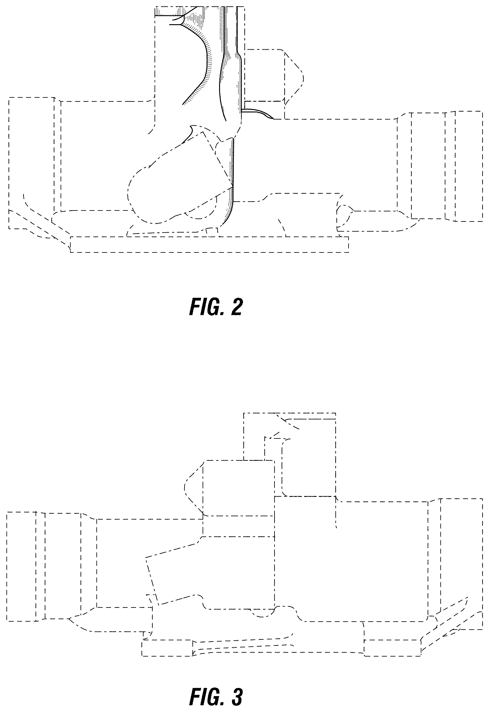
FIG. 2 is a right side elevation view thereof;
FIG. 3 is a left side elevation view thereof;
FIG. 4 is a top side elevation view thereof;
FIG. 5 is a bottom side elevation view thereof;
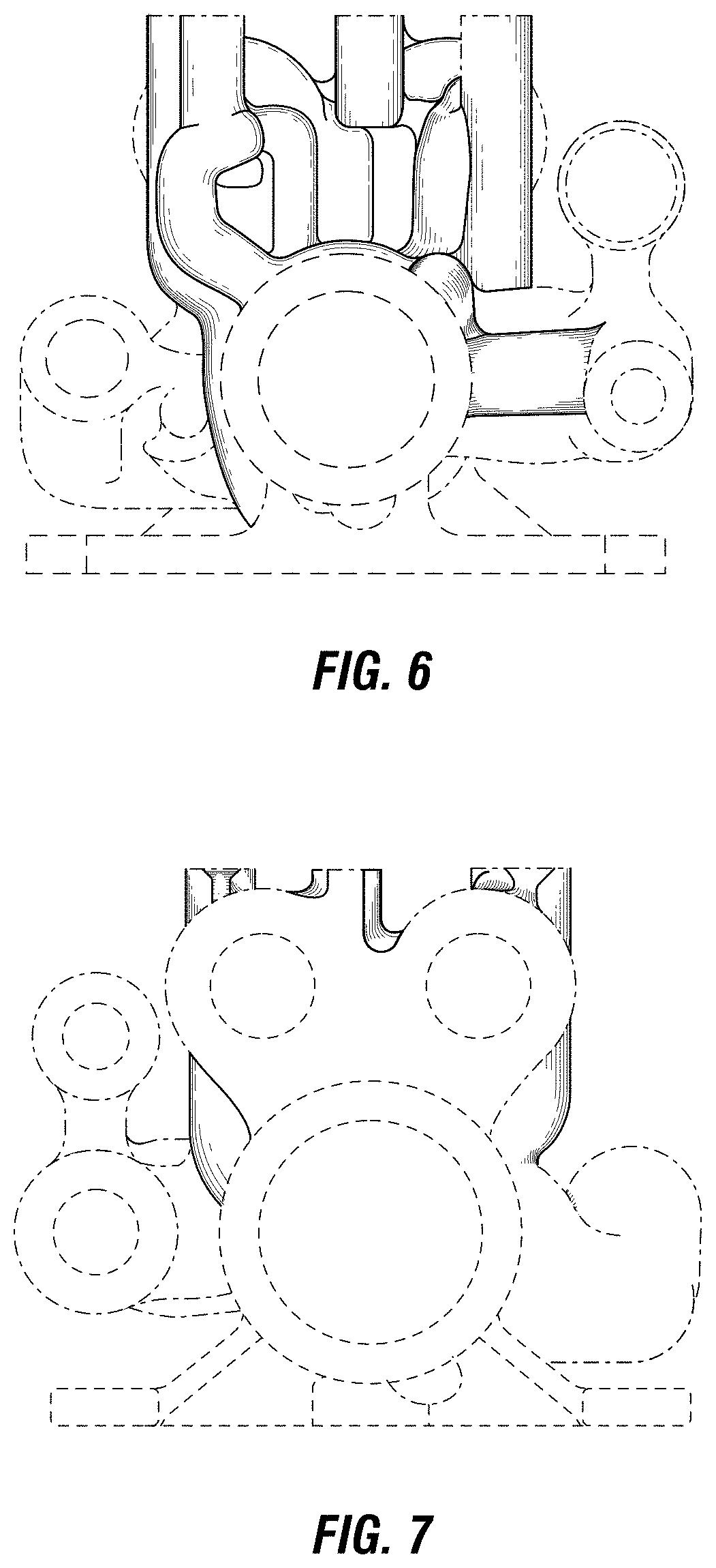
FIG. 6 is a front side elevation view thereof; and,
FIG. 7 is a back side elevation view thereof.
The evenly spaced broken lines depict portions of the manifold and environmental subject matter that forms no part of the claim. The dash-dot broken lines represent boundaries of the claim and form no part thereof.
* * * * *
D00000
D00001
D00002
D00003
D00004
XML
uspto.report is an independent third-party trademark research tool that is not affiliated, endorsed, or sponsored by the United States Patent and Trademark Office (USPTO) or any other governmental organization. The information provided by uspto.report is based on publicly available data at the time of writing and is intended for informational purposes only.
While we strive to provide accurate and up-to-date information, we do not guarantee the accuracy, completeness, reliability, or suitability of the information displayed on this site. The use of this site is at your own risk. Any reliance you place on such information is therefore strictly at your own risk.
All official trademark data, including owner information, should be verified by visiting the official USPTO website at www.uspto.gov. This site is not intended to replace professional legal advice and should not be used as a substitute for consulting with a legal professional who is knowledgeable about trademark law.