Mini pocket hole jig
Schaaf , et al. October 13, 2
U.S. patent number D898,785 [Application Number D/689,333] was granted by the patent office on 2020-10-13 for mini pocket hole jig. This patent grant is currently assigned to KREG ENTERPRISES, INC.. The grantee listed for this patent is Kreg Enterprises, Inc.. Invention is credited to Timothy J. Forbes, Brian Hill, Neil M. Holland, Scott Schaaf.


View All Diagrams
| United States Patent | D898,785 |
| Schaaf , et al. | October 13, 2020 |
Mini pocket hole jig
Claims
CLAIM The ornamental design for a mini pocket hole jig, as shown and described.
| Inventors: | Schaaf; Scott (Ankeny, IA), Forbes; Timothy J. (Ankeny, IA), Holland; Neil M. (Slater, IA), Hill; Brian (Ames, IA) | ||||||||||
|---|---|---|---|---|---|---|---|---|---|---|---|
| Applicant: |
|
||||||||||
| Assignee: | KREG ENTERPRISES, INC. (Huxley,
IA) |
||||||||||
| Family ID: | 68290588 | ||||||||||
| Appl. No.: | D/689,333 | ||||||||||
| Filed: | April 29, 2019 |
Related U.S. Patent Documents
| Application Number | Filing Date | Patent Number | Issue Date | ||
|---|---|---|---|---|---|
| 16397260 | Apr 29, 2019 | ||||
| 62664335 | Apr 30, 2018 | ||||
| 62785967 | Dec 28, 2018 | ||||
| Current U.S. Class: | D15/140 |
| Current CPC Class: | B23B47/287 20130101; B23B2247/10 20130101; B23B2260/088 20130101; Y10T408/567 20150115 |
| Current International Class: | 1509 |
| Field of Search: | ;D8/70,71,74 ;D15/131,132,138,140 |
References Cited [Referenced By]
U.S. Patent Documents
| 5322396 | June 1994 | Blacker |
| 5676500 | October 1997 | Sommerfeld |
| 5791835 | August 1998 | Chlang et al. |
| 6254320 | July 2001 | Weinstein et al. |
| 6394712 | May 2002 | Weinstein et al. |
| 6599064 | July 2003 | Robinson |
| 6726411 | April 2004 | Sommerfeld et al. |
| D503415 | March 2005 | Dembicks |
| 6955508 | October 2005 | Radcliffe |
| D528930 | September 2006 | Degen |
| 7101123 | September 2006 | Weinstein et al. |
| 7134814 | November 2006 | Park |
| D567269 | April 2008 | Sion |
| 7374373 | May 2008 | Park et al. |
| 7484914 | February 2009 | Weinstein et al. |
| 7597513 | October 2009 | Chang |
| 7670089 | March 2010 | Chiang |
| 7798750 | September 2010 | Clark |
| 8052358 | November 2011 | McDaniel et al. |
| 8083443 | December 2011 | Circosta et al. |
| D651885 | January 2012 | Banasik |
| 8087853 | January 2012 | Stukuls |
| 8231313 | July 2012 | Sommerfeld et al. |
| 8840345 | September 2014 | Park |
| 9682430 | June 2017 | Clark |
| 9782837 | October 2017 | Pelkey |
| D809032 | January 2018 | Cummings |
| D809578 | February 2018 | Cummings |
| 9969011 | May 2018 | Marusiak |
| 9969042 | May 2018 | Clark |
| 10022808 | July 2018 | Chang |
| 10144068 | December 2018 | Poole |
| 10173269 | January 2019 | Cattaneo |
| 10286458 | May 2019 | Brigham |
| 10315295 | June 2019 | Vandenberg |
| 10343222 | July 2019 | Schwagerle et al. |
| 10357831 | July 2019 | Evatt et al. |
| D872147 | January 2020 | Hall |
| D872554 | January 2020 | Miller |
| 2003/0123941 | July 2003 | Emerson |
| 2004/0253065 | December 2004 | Davis |
| 2005/0089381 | April 2005 | Liu et al. |
| 2006/0228180 | October 2006 | Sommerfeld |
| 2007/0201961 | August 2007 | Chiang |
| 2007/0280797 | December 2007 | McDaniel et al. |
| 2008/0075546 | March 2008 | Lin |
| 2008/0099101 | May 2008 | Chiang |
| 2008/0187404 | August 2008 | Chiang |
| 2008/0219786 | September 2008 | Sommerfeld |
| 2011/0150587 | June 2011 | Stukuls |
| 2012/0051865 | March 2012 | Liu |
| 2016/0158850 | June 2016 | Fisher |
| 2017/0087644 | March 2017 | Pelkey |
| 2018/0071835 | March 2018 | Poole |
| 2018/0141133 | May 2018 | Clark |
| 2018/0185930 | July 2018 | Duginske |
| 2018/0214959 | August 2018 | Evatt |
| 2018/0214960 | August 2018 | Evatt et al. |
| 2018/0290217 | October 2018 | Asimakis |
| 2018/0345385 | December 2018 | Yates et al. |
| 2019/0015903 | January 2019 | Schleicher |
| 2019/0030619 | January 2019 | Thackery |
| 2019/0047058 | February 2019 | Pikarski et al. |
| 2019/0054547 | February 2019 | Pikarski et al. |
| 2019/0111499 | April 2019 | Evatt et al. |
| 2019/0126360 | May 2019 | Marra, Jr. |
| 2019/0176247 | June 2019 | Chang |
| 2019/0217402 | July 2019 | Brigham |
| 2019/0329329 | October 2019 | Schaaf |
| 2019/0344362 | November 2019 | Hall |
| 8345001 | Mar 2002 | AU | |||
| 2014295887 | Feb 2016 | AU | |||
| 2018101034 | Aug 2018 | AU | |||
| 3012668 | Jan 2019 | CA | |||
| 102004023343 | Dec 2005 | DE | |||
| 202006005977 | Aug 2006 | DE | |||
| 60125047 | Jul 2007 | DE | |||
| 202012103274 | Sep 2012 | DE | |||
| 202017101885 | May 2017 | DE | |||
| 202018104374 | Sep 2018 | DE | |||
| 102004023343 | Jan 2019 | DE | |||
| 102017115668 | Jan 2019 | DE | |||
| 1712315 | Oct 2006 | EP | |||
| 1311364 | Dec 2006 | EP | |||
| 1595627 | Apr 2008 | EP | |||
| 2512763 | Oct 2012 | EP | |||
| 2223762 | Jul 2015 | EP | |||
| 3027364 | Jun 2016 | EP | |||
| 3391984 | Oct 2018 | EP | |||
| 3444057 | Feb 2019 | EP | |||
| 3444058 | Feb 2019 | EP | |||
| 3446817 | Feb 2019 | EP | |||
| 2346573 | Aug 2000 | GB | |||
| 2496473 | May 2013 | GB | |||
| 201806455 | Oct 2018 | GB | |||
| 2564944 | Jan 2019 | GB | |||
| 2567053 | Apr 2019 | GB | |||
| 2567056 | Apr 2019 | GB | |||
Attorney, Agent or Firm: Proskey; Christopher A. BrownWinick Law Firm
Description
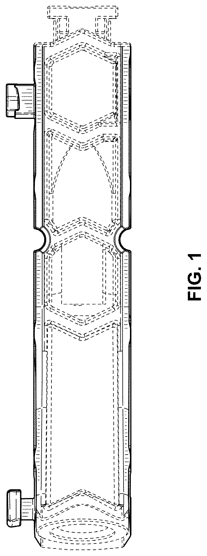
FIG. 1 is a top elevational view of a mini pocket hole jig;
FIG. 2 is a bottom elevational view of a mini pocket hole jig;
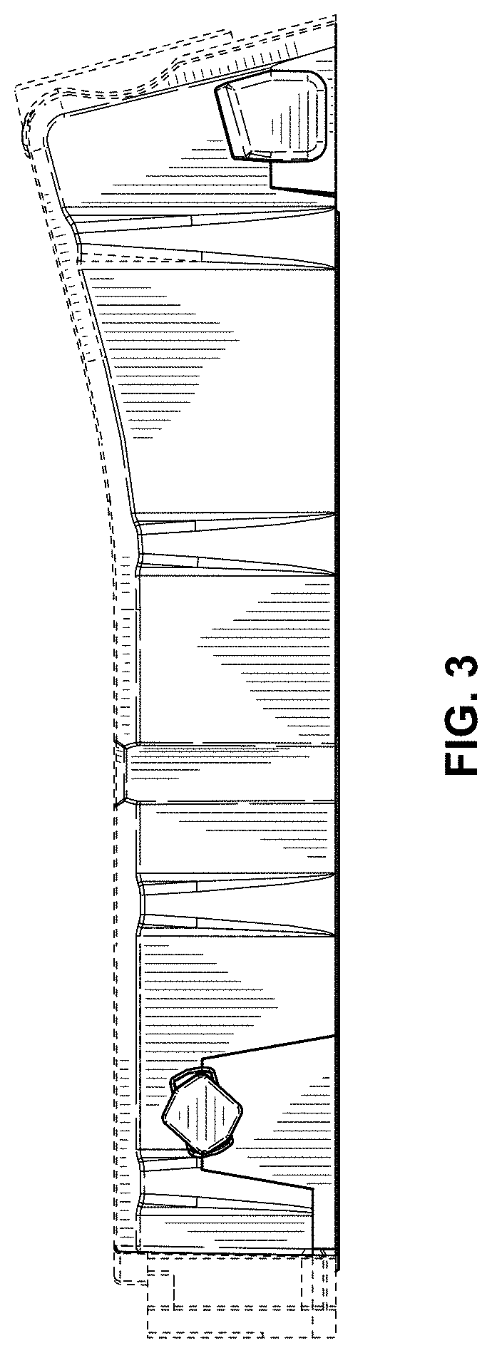
FIG. 3 is a side elevational view of a mini pocket hole jig;
FIG. 4 is another side elevational view of a mini pocket hole jig;
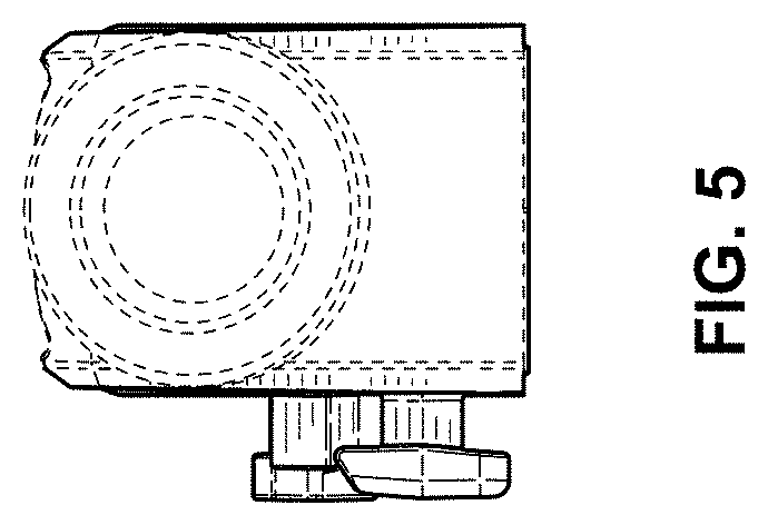
FIG. 5 is a rear elevational view of a mini pocket hole jig;
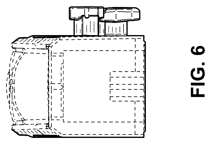
FIG. 6 is a front elevational view of a mini pocket hole jig;
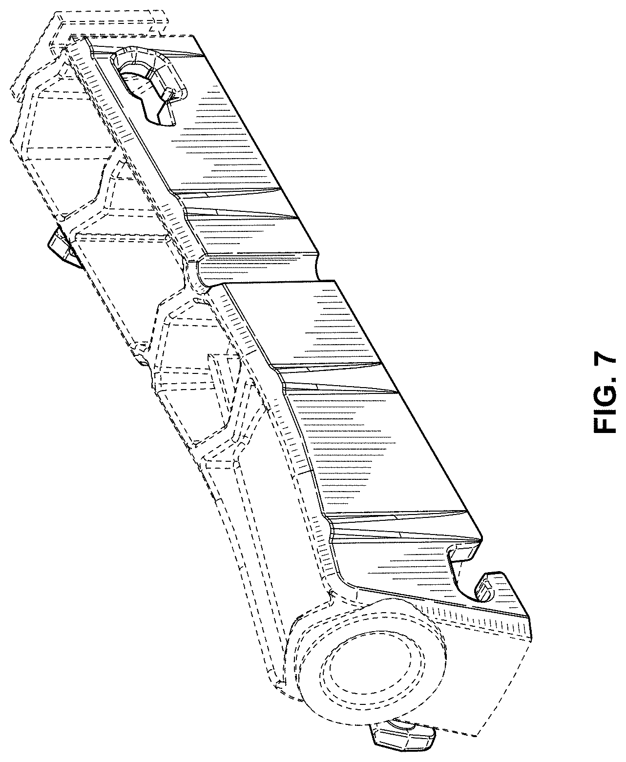
FIG. 7 is a top rear perspective view of a mini pocket hole jig;
FIG. 8 is another top rear perspective view of a mini pocket hole jig;
FIG. 9 is a bottom rear perspective view of a mini pocket hole jig;
FIG. 10 is another bottom rear perspective view of a mini pocket hole jig;
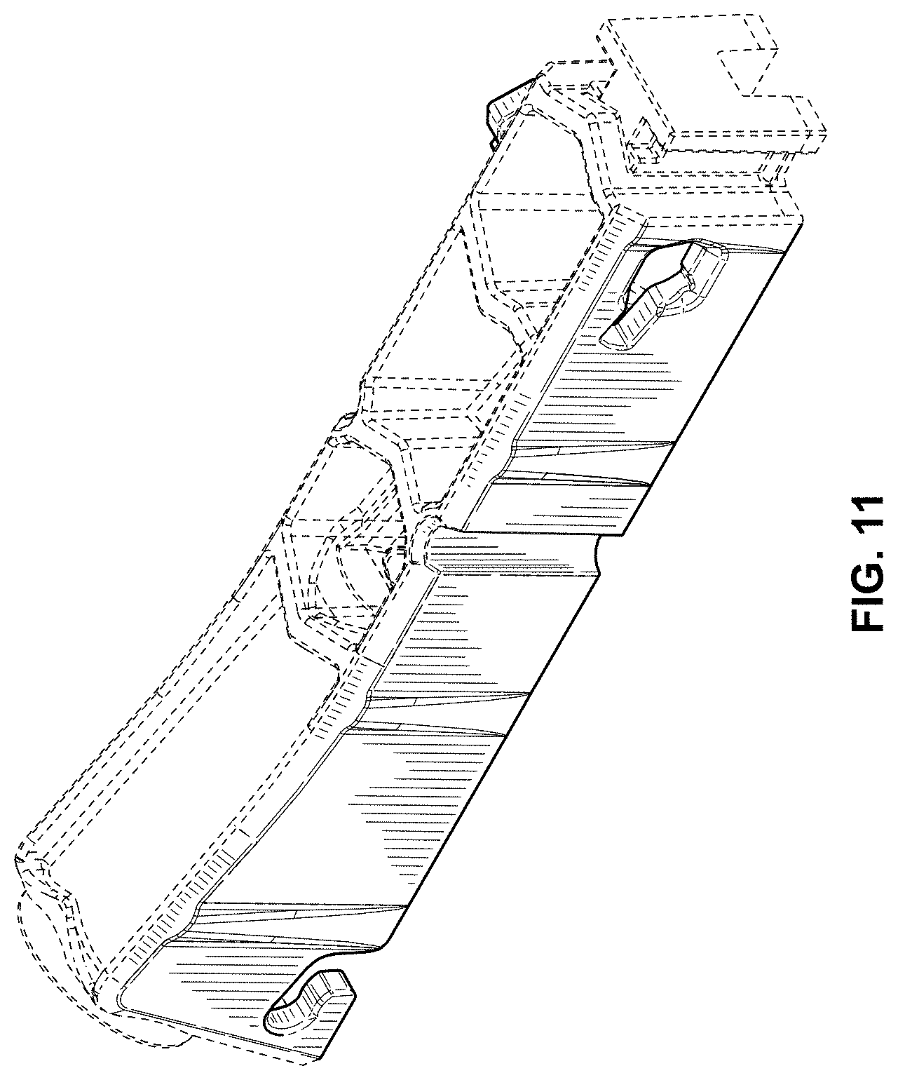
FIG. 11 is a top front perspective view of a mini pocket hole jig;
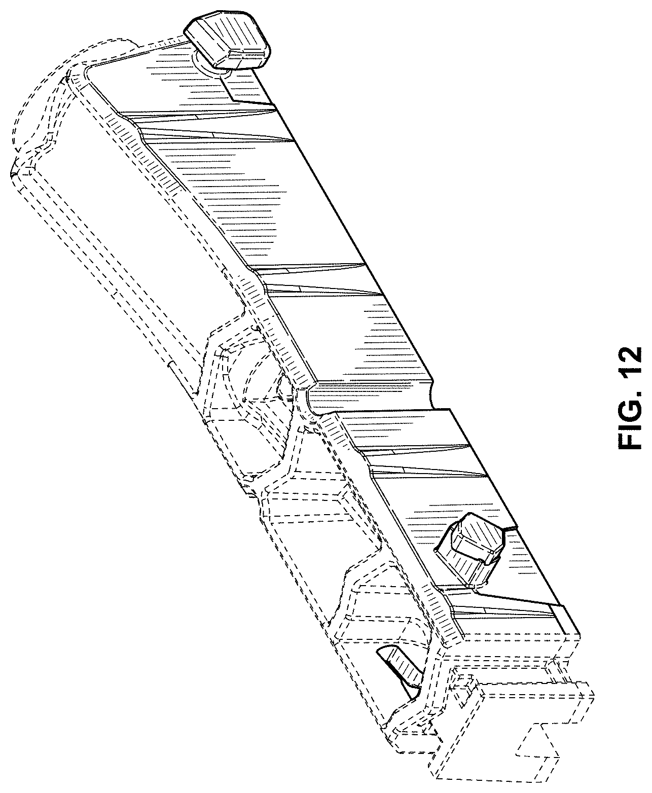
FIG. 12 is another top front perspective view of a mini pocket hole jig;
FIG. 13 is a bottom front perspective view of a mini pocket hole jig;
FIG. 14 is another bottom front perspective view of a mini pocket hole jig;
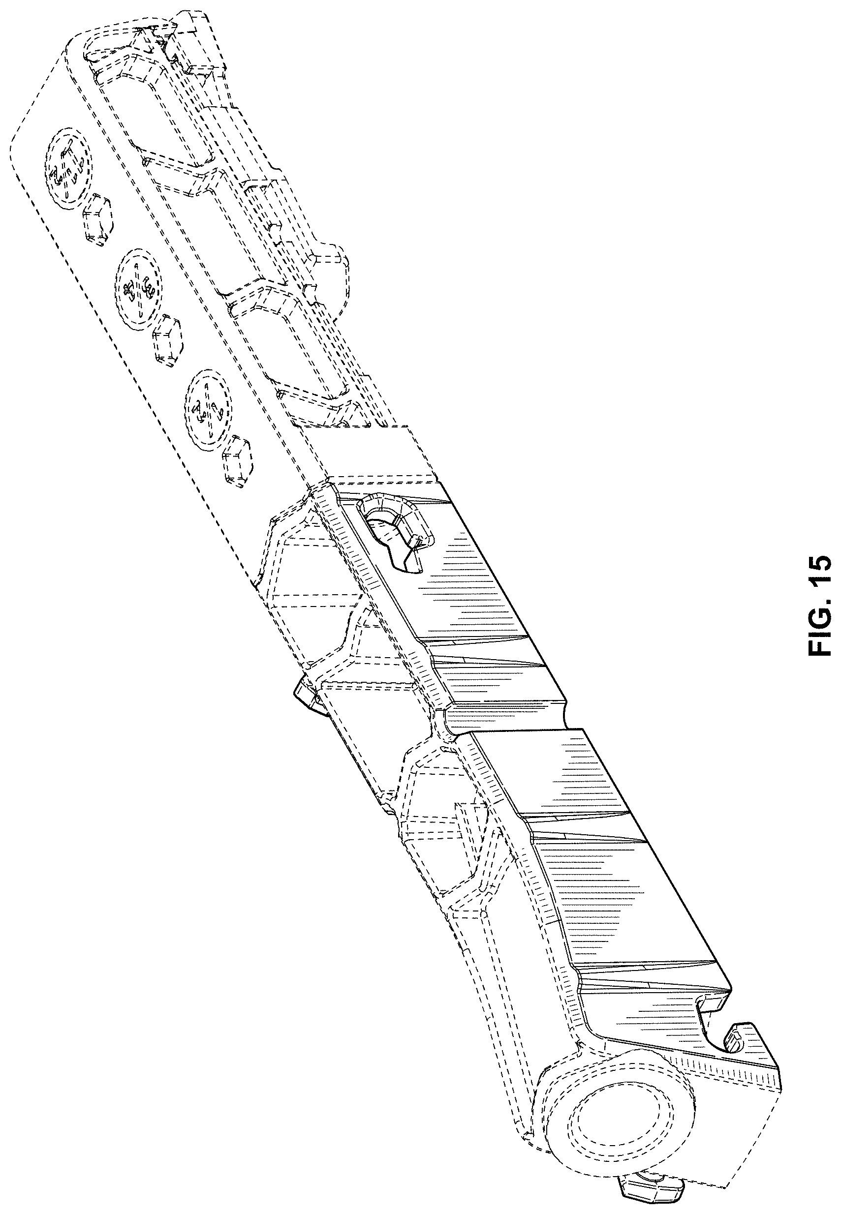
FIG. 15 is a top rear perspective view of a mini pocket hole jig, shown in connection with an attached tail section, as shown in dashed lines for intended use purposes;
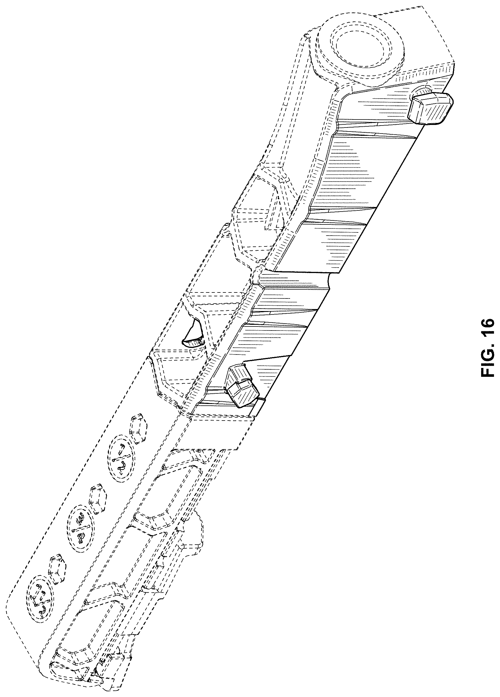
FIG. 16 is another top rear perspective view of a mini pocket hole jig, shown in connection with an attached tail section, as shown in dashed lines for intended use purposes;
FIG. 17 is a bottom rear perspective view of a mini pocket hole jig, shown in connection with an attached tail section, as shown in dashed lines for intended use purposes;
FIG. 18 is a top front perspective view of a mini pocket hole jig, shown in connection with an attached tail section, as shown in dashed lines for intended use purposes;
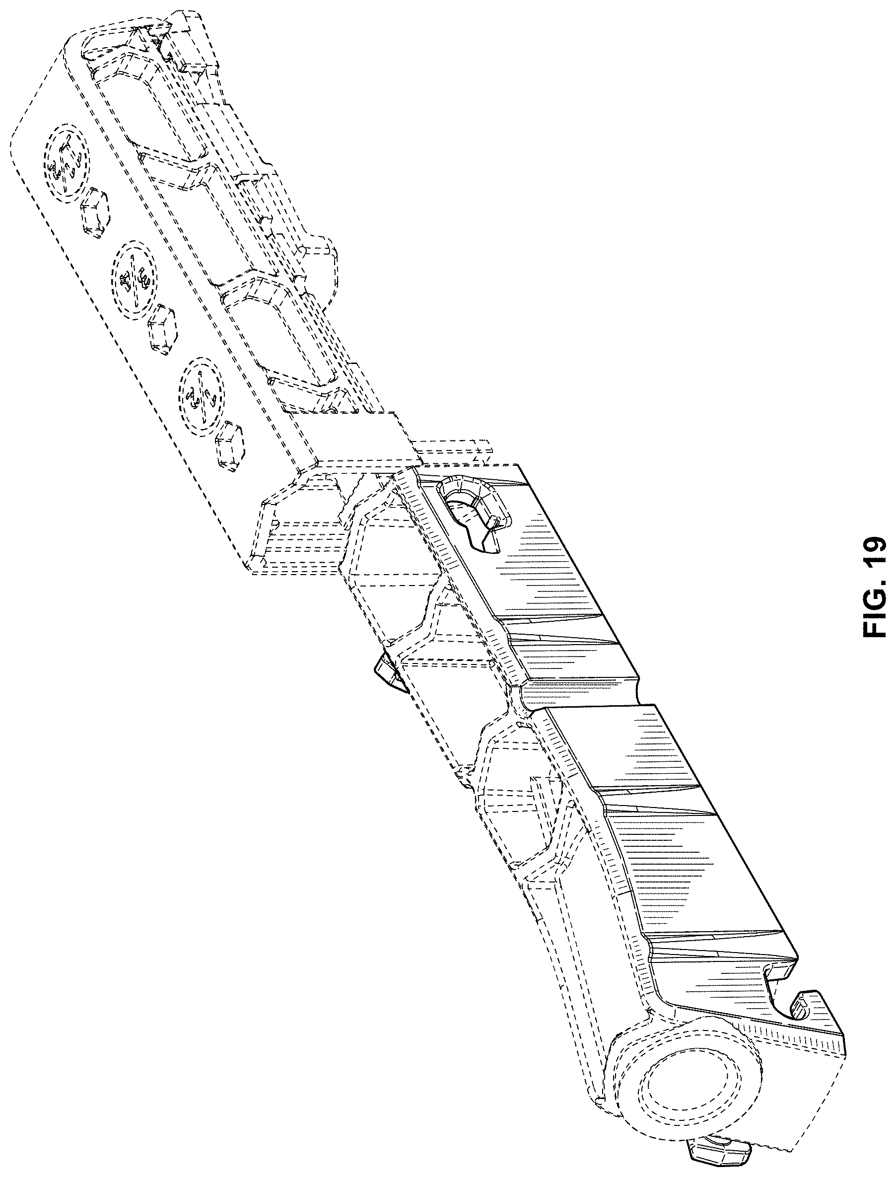
FIG. 19 is a top rear perspective view of a mini pocket hole jig, shown in partial connection with an attached tail section, as shown in dashed lines for intended use purposes;
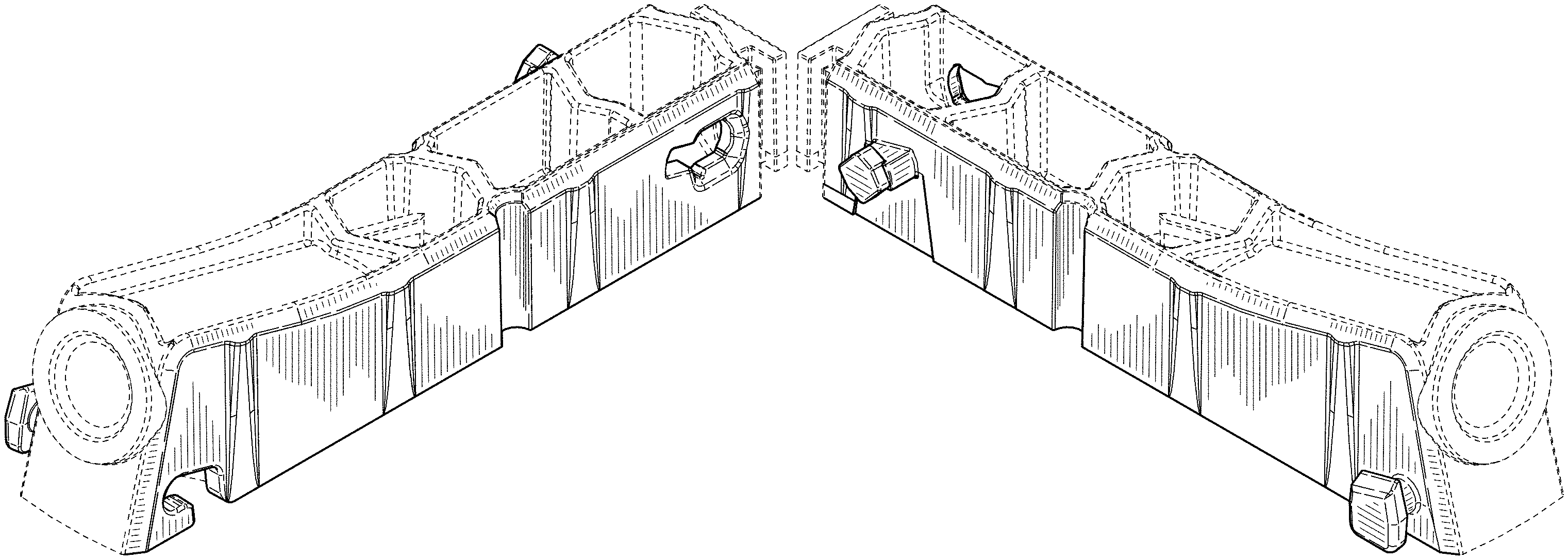
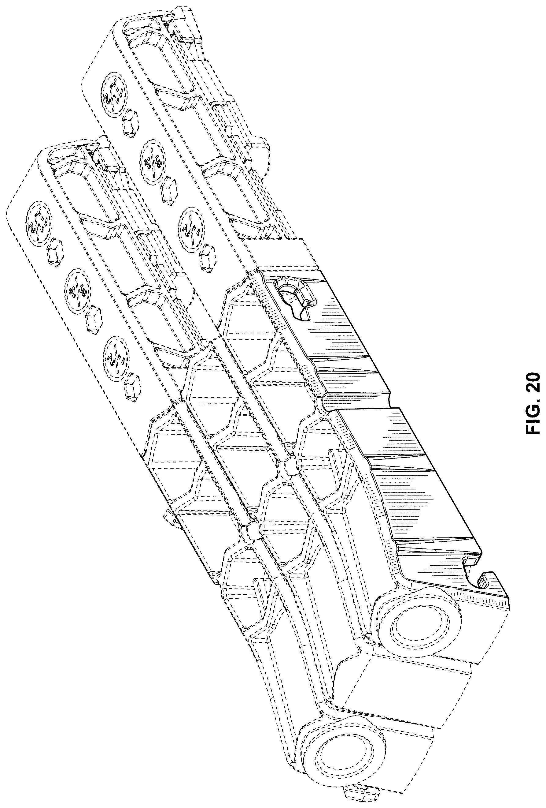
FIG. 20 is a top rear perspective view of a mini pocket hole jig, shown in connection with an attached tail section, a spacer, and a second mini pocket hole jig and attached tail section, as shown in dashed lines for intended use purposes;
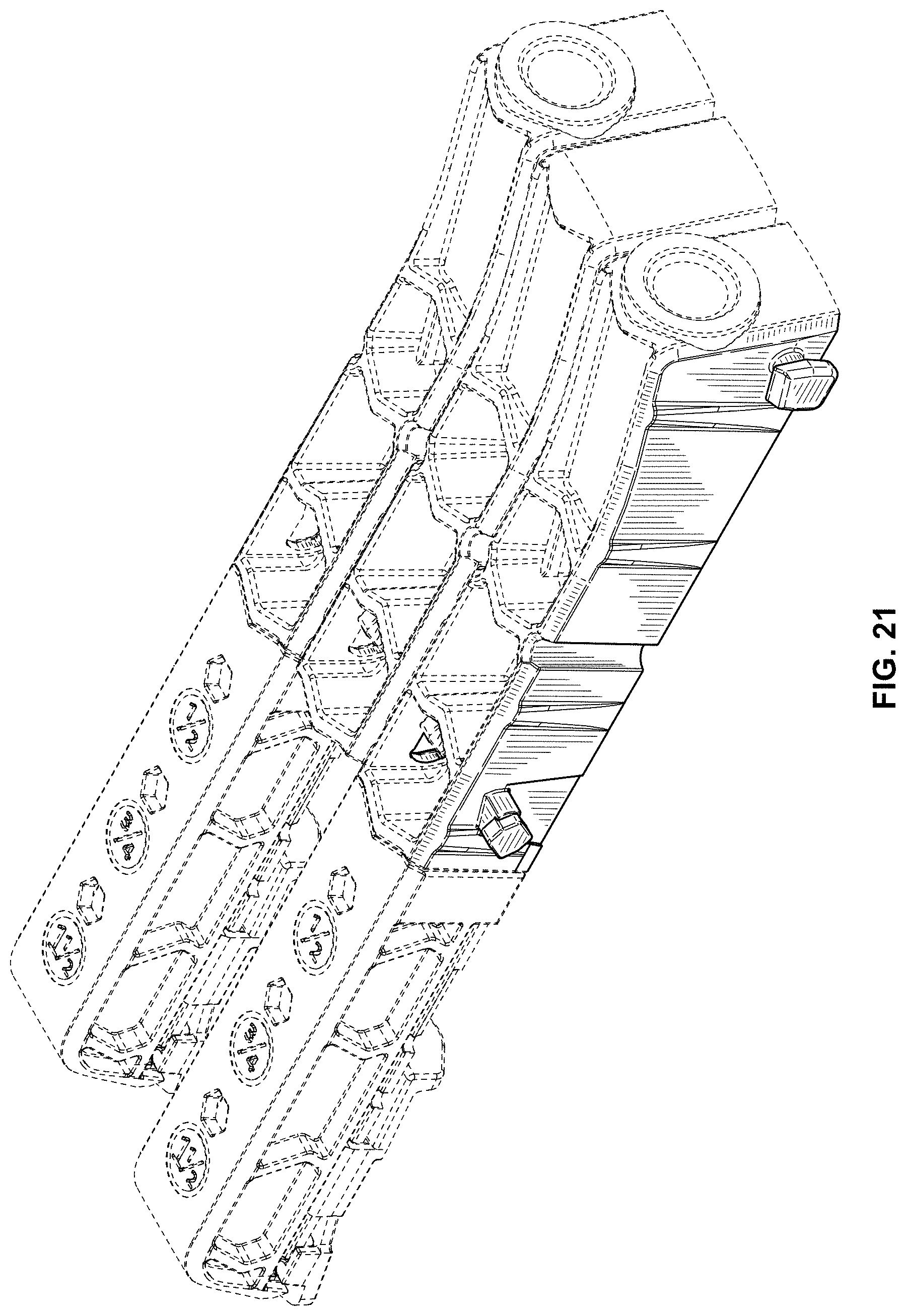
FIG. 21 is another top rear perspective view of a mini pocket hole jig, shown in connection with an attached tail section, a spacer, and a second mini pocket hole jig and attached tail section, as shown in dashed lines for intended use purposes;
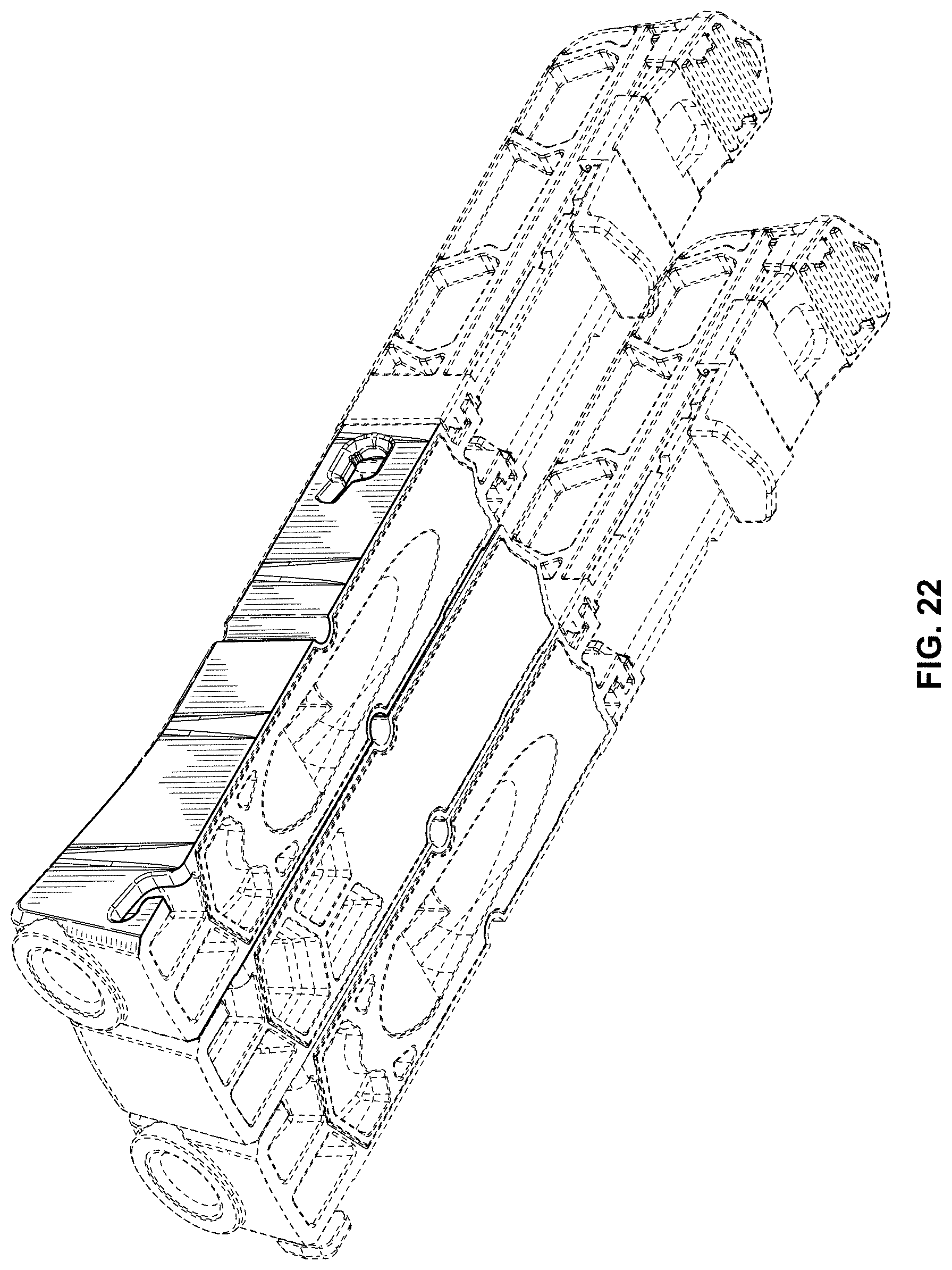
FIG. 22 is bottom rear perspective view of a mini pocket hole jig, shown in connection with an attached tail section, a spacer, and a second mini pocket hole jig and attached tail section, as shown in dashed lines for intended use purposes;
FIG. 23 is a top front perspective view of a mini pocket hole jig, shown in connection with an attached tail section, a spacer, and a second mini pocket hole jig and attached tail section, as shown in dashed lines for intended use purposes; and,
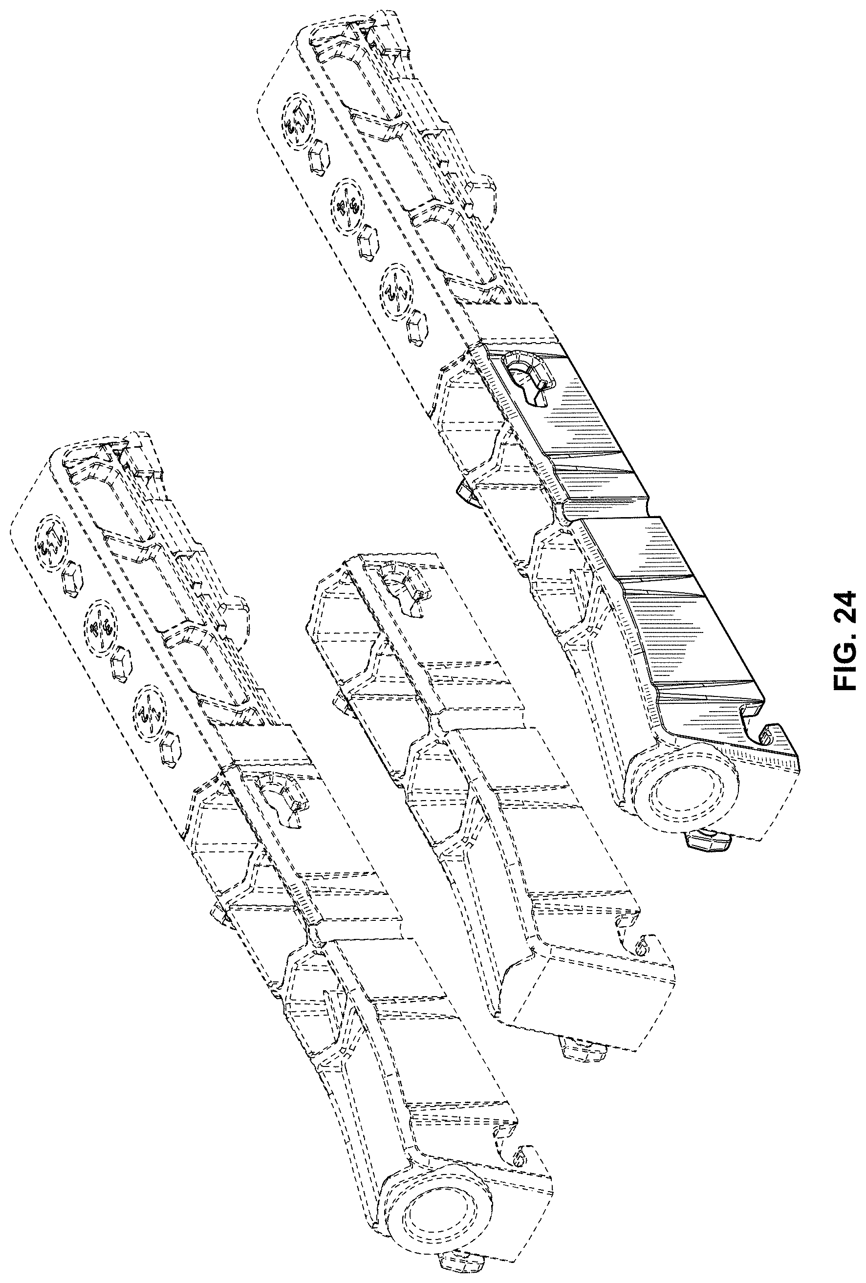
FIG. 24 is a top rear exploded perspective view of a mini pocket hole jig, shown in connection with an attached tail section, a spacer, and a second mini pocket hole jig and attached tail section, as shown in dashed lines for intended use purposes.
The dashed lines shown represent the environment and represent unclaimed subject matter and form no part of the claimed design.
* * * * *
D00000
D00001
D00002
D00003
D00004
D00005
D00006
D00007
D00008
D00009
D00010
D00011
D00012
D00013

D00014

D00015
D00016
D00017

D00018

D00019
D00020
D00021
D00022
D00023

D00024
XML
uspto.report is an independent third-party trademark research tool that is not affiliated, endorsed, or sponsored by the United States Patent and Trademark Office (USPTO) or any other governmental organization. The information provided by uspto.report is based on publicly available data at the time of writing and is intended for informational purposes only.
While we strive to provide accurate and up-to-date information, we do not guarantee the accuracy, completeness, reliability, or suitability of the information displayed on this site. The use of this site is at your own risk. Any reliance you place on such information is therefore strictly at your own risk.
All official trademark data, including owner information, should be verified by visiting the official USPTO website at www.uspto.gov. This site is not intended to replace professional legal advice and should not be used as a substitute for consulting with a legal professional who is knowledgeable about trademark law.