External plug for an electrical apparatus enclosure
Lanter, Jr. October 6, 2
U.S. patent number D897,976 [Application Number D/676,315] was granted by the patent office on 2020-10-06 for external plug for an electrical apparatus enclosure. This patent grant is currently assigned to Eaton Intelligent Power Limited. The grantee listed for this patent is Eaton Intelligent Power Limited. Invention is credited to Roger Wayne Lanter, Jr..


| United States Patent | D897,976 |
| Lanter, Jr. | October 6, 2020 |
External plug for an electrical apparatus enclosure
Claims
CLAIM The ornamental design for an external plug for an electrical apparatus enclosure, as shown and described.
| Inventors: | Lanter, Jr.; Roger Wayne (Auburn, IL) | ||||||||||
|---|---|---|---|---|---|---|---|---|---|---|---|
| Applicant: |
|
||||||||||
| Assignee: | Eaton Intelligent Power Limited
(Dublin, IE) |
||||||||||
| Appl. No.: | D/676,315 | ||||||||||
| Filed: | January 10, 2019 |
Related U.S. Patent Documents
| Application Number | Filing Date | Patent Number | Issue Date | ||
|---|---|---|---|---|---|
| 29598236 | Mar 23, 2017 | D842827 | |||
| Current U.S. Class: | D13/184 |
| Current International Class: | 1303 |
| Field of Search: | ;D13/112-118,122,184,145,147,152 ;D14/231 |
References Cited [Referenced By]
U.S. Patent Documents
| 2871284 | January 1959 | Wills |
| 2934660 | April 1960 | Brunner |
| 3315556 | April 1967 | Speck |
| 3767977 | October 1973 | Bachman |
| 4024441 | May 1977 | Coyle et al. |
| 4166934 | September 1979 | Marrero |
| D265986 | August 1982 | Wearsch |
| 5072071 | December 1991 | Cassity et al. |
| D324816 | March 1992 | LeDuc |
| 5213518 | May 1993 | Weidler |
| 5272592 | December 1993 | Harris et al. |
| D343825 | February 1994 | Enderby |
| 5307243 | April 1994 | Sharp et al. |
| D370463 | June 1996 | Nagele et al. |
| 5696664 | December 1997 | Rose |
| D410437 | June 1999 | Mowery |
| D419966 | February 2000 | Mowery et al. |
| D424026 | May 2000 | Kabat |
| D449279 | October 2001 | Takach, Jr. |
| D450665 | November 2001 | Isely |
| D566657 | April 2008 | Shen |
| D577986 | October 2008 | Jarvis |
| D584700 | January 2009 | Urry |
| 7485817 | February 2009 | Gottschalk |
| D606033 | December 2009 | Sonntag |
| D637162 | May 2011 | Bridgman |
| 7968794 | June 2011 | Baldwin |
| D684935 | June 2013 | DeCosta |
| D696189 | December 2013 | Muto |
| 8729988 | May 2014 | Maloney |
| D711324 | August 2014 | Pritchett |
| D739833 | September 2015 | Hanazeder |
| D742340 | November 2015 | Krivonak et al. |
| D760230 | June 2016 | Lizuka et al. |
| D767514 | September 2016 | Summers et al. |
| D767571 | September 2016 | Iizuka et al. |
| 9462731 | October 2016 | Onishi et al. |
| D776619 | January 2017 | Gretz |
| D781237 | March 2017 | Wilkins, III |
| D798813 | October 2017 | Marinelli et al. |
| D814420 | April 2018 | Chen |
| D816049 | April 2018 | Kim |
| 10000956 | June 2018 | Whitaker et al. |
| D842825 | March 2019 | Lanter, Jr. |
| D842826 | March 2019 | Lanter, Jr. |
| D842827 | March 2019 | Lanter, Jr. |
| 2002/0182896 | December 2002 | Welsh et al. |
| 2009/0302724 | December 2009 | Allard et al. |
| 2011/0149483 | June 2011 | Diaz et al. |
| 2013/0241359 | September 2013 | Naito et al. |
| 2014/0185195 | July 2014 | Samuelson |
| 2015/0155849 | June 2015 | Kikuchi |
Other References
|
Photographs of Prior Art Products--"GE loadcenter showing a two direction assembly into the enclosure and then a slide to the final position" (1 page) (date unknown, but prior to filing date of the present application). cited by applicant . Photographs of Prior Art Products--"Siemens loadcenter showing a two direction assembly into the enclosure and then a slide to the final position" (1 page) (date unknown, but prior to filing date of the present application). cited by applicant . Photographs of Prior Art Products--"Square D Loadcenter showing a two direction assembly into the enclosure and then a slide to the final position" (1 page) (date unknown, but prior to filing date of the present application). cited by applicant. |
Primary Examiner: Posthauer; Catherine S
Assistant Examiner: Ofstun; Alison M
Attorney, Agent or Firm: Myers Bigel, P.A.
Description
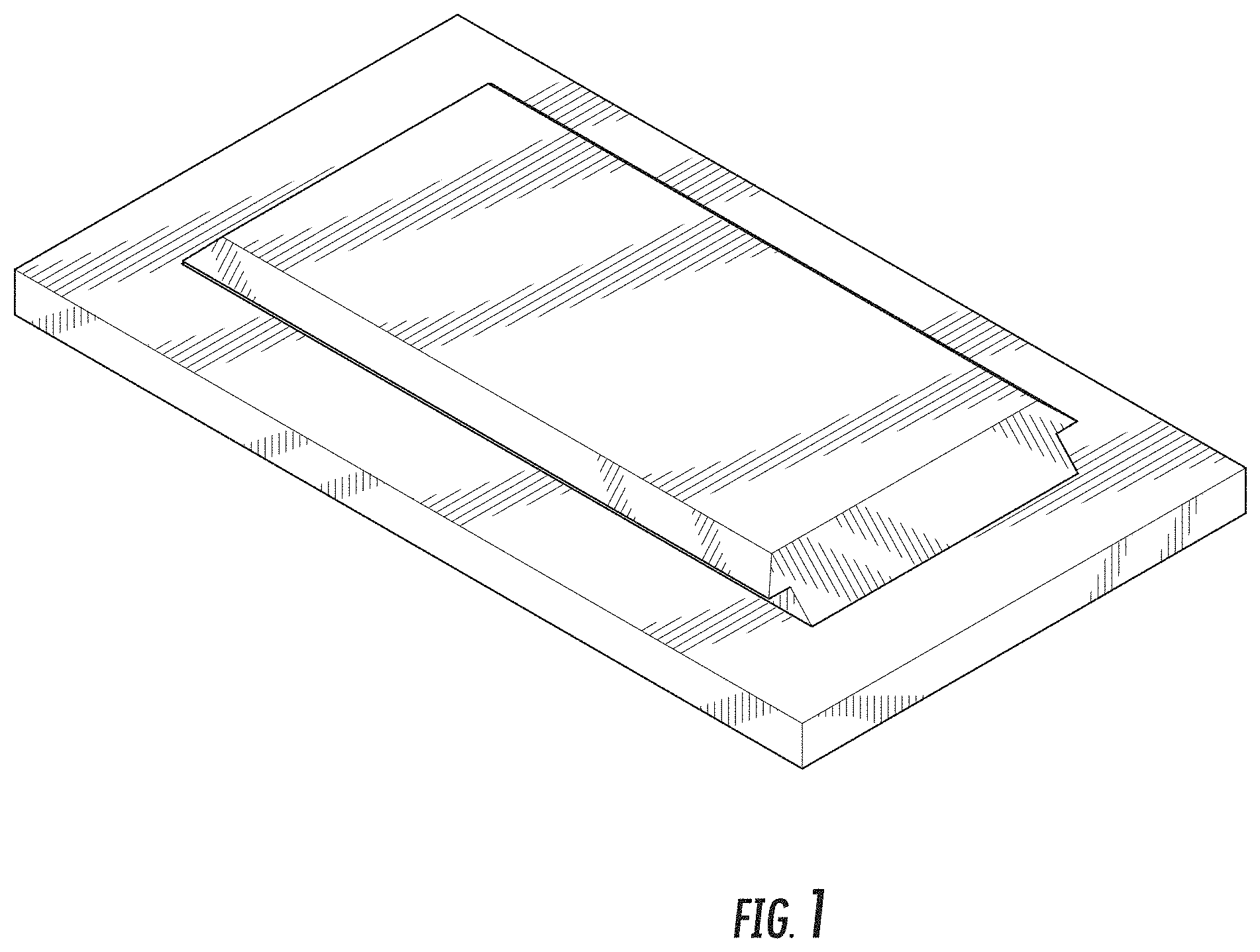
FIG. 1 is a top, side perspective view of an external plug for an electrical apparatus enclosure, showing my new design;
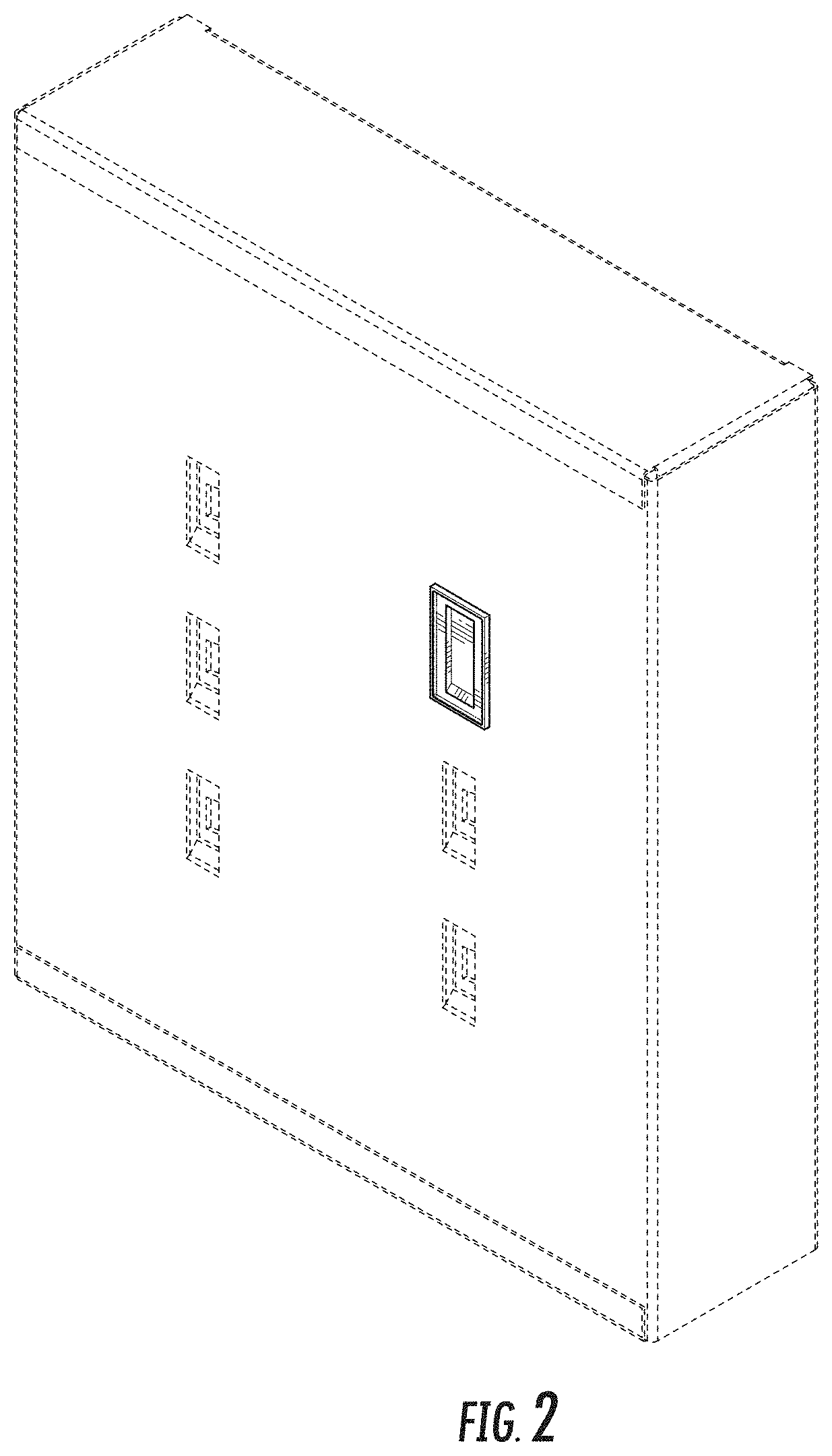
FIG. 2 is a bottom perspective view thereof, shown in an environment of use;
FIG. 3 is a long side view thereof;
FIG. 4 is an opposing long side view thereof;
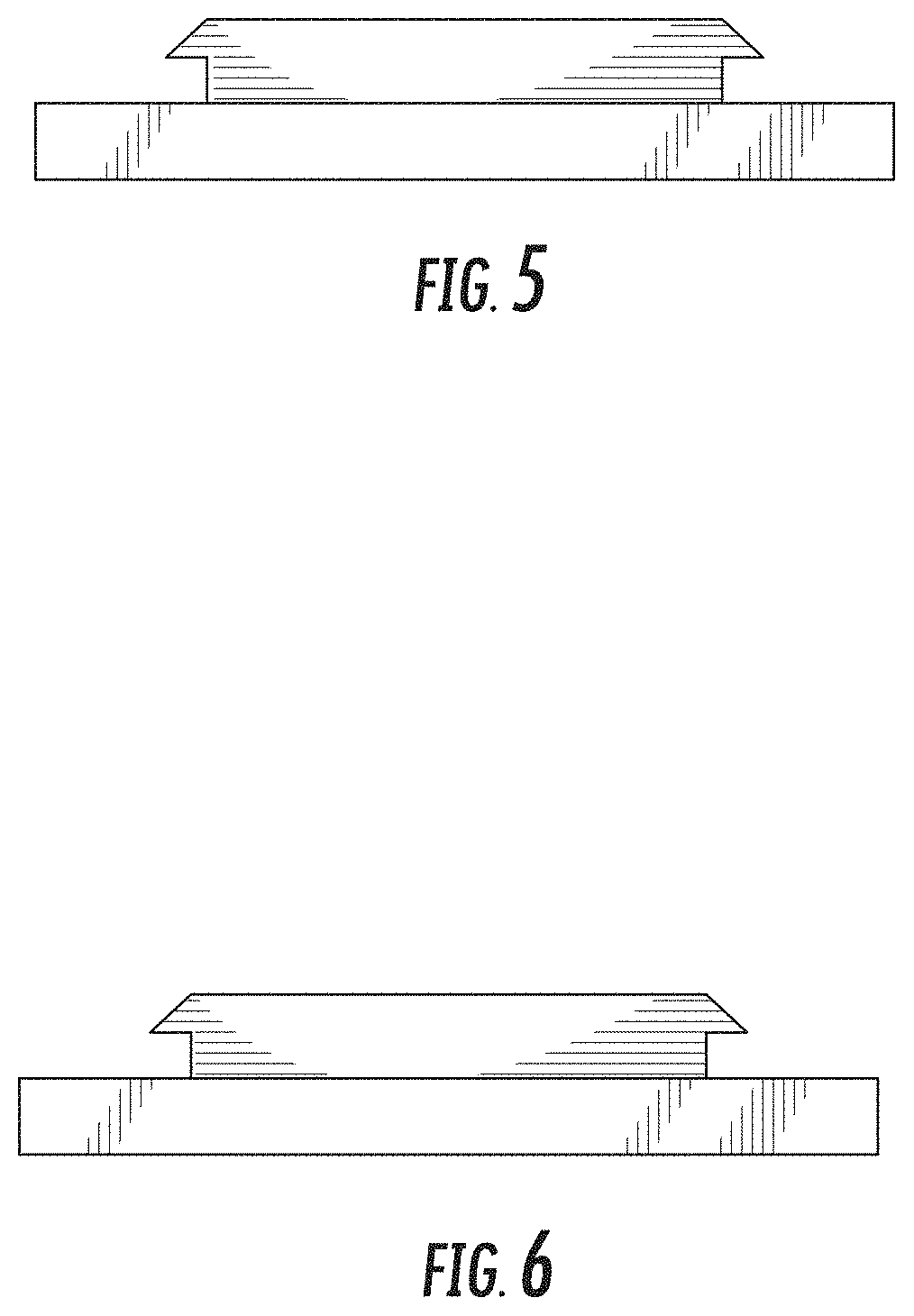
FIG. 5 is an end view thereof;
FIG. 6 is an opposing end view thereof;
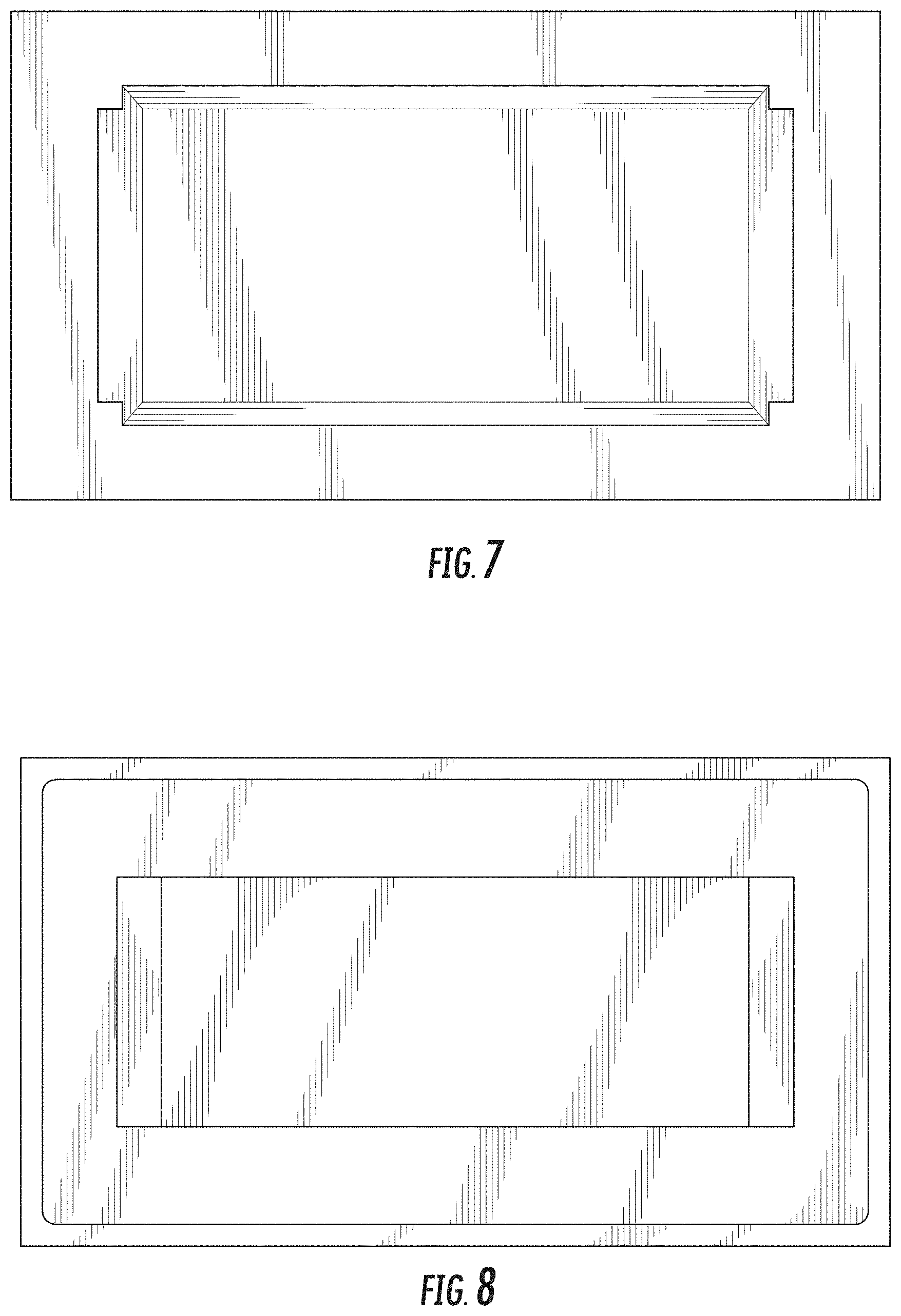
FIG. 7 is a top view thereof;
FIG. 8 is a bottom view thereof; and,
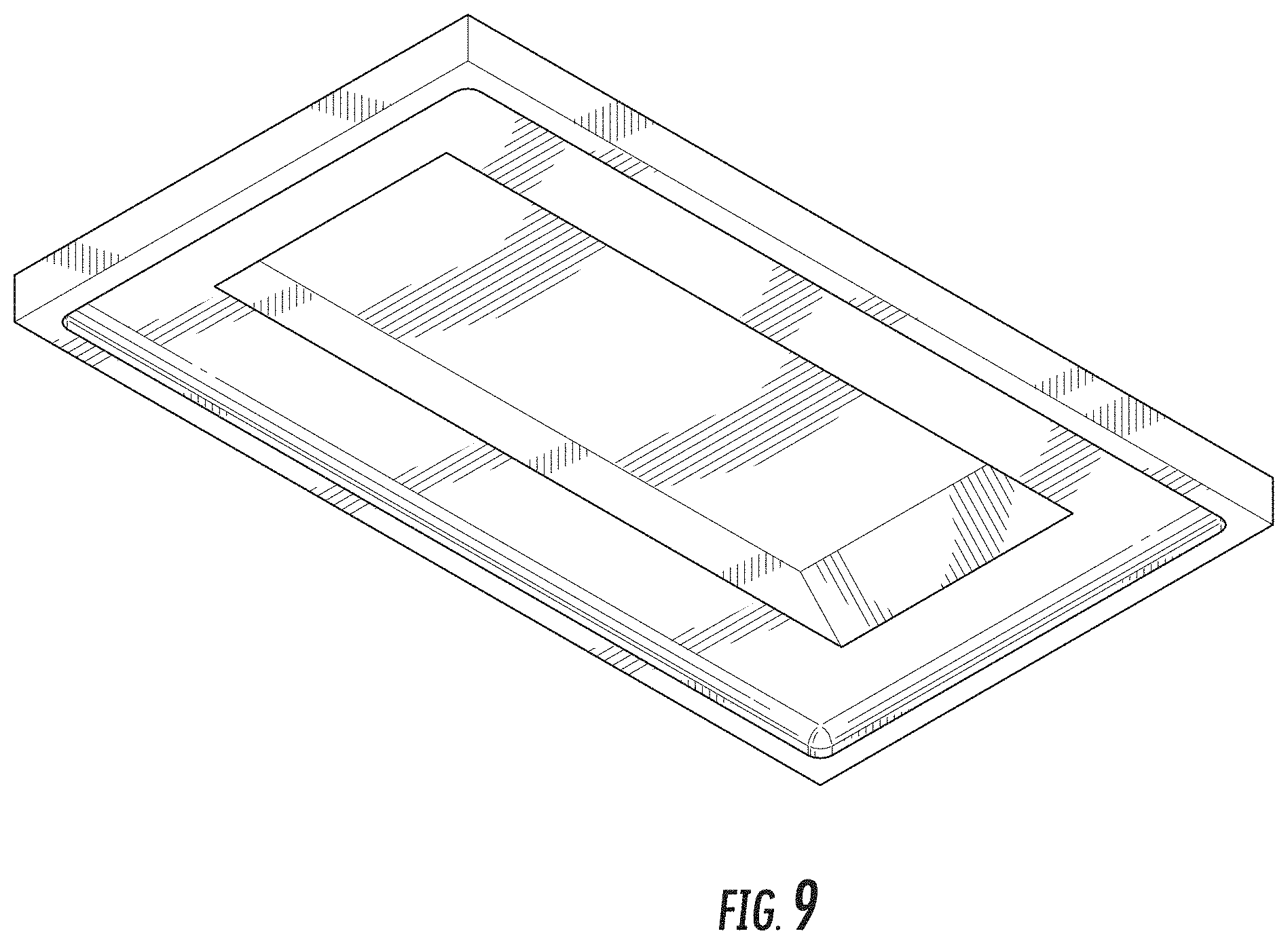
FIG. 9 is a bottom perspective view thereof.
The broken lines in FIG. 2 represent environmental subject matter and form no part of the claimed design.
* * * * *
D00000
D00001
D00002
D00003
D00004
D00005
D00006
XML
uspto.report is an independent third-party trademark research tool that is not affiliated, endorsed, or sponsored by the United States Patent and Trademark Office (USPTO) or any other governmental organization. The information provided by uspto.report is based on publicly available data at the time of writing and is intended for informational purposes only.
While we strive to provide accurate and up-to-date information, we do not guarantee the accuracy, completeness, reliability, or suitability of the information displayed on this site. The use of this site is at your own risk. Any reliance you place on such information is therefore strictly at your own risk.
All official trademark data, including owner information, should be verified by visiting the official USPTO website at www.uspto.gov. This site is not intended to replace professional legal advice and should not be used as a substitute for consulting with a legal professional who is knowledgeable about trademark law.