Hand-held power tool and a display on a hand-held power tool
Konnecke , et al. September 29, 2
U.S. patent number D897,174 [Application Number D/666,919] was granted by the patent office on 2020-09-29 for hand-held power tool and a display on a hand-held power tool. This patent grant is currently assigned to GUSTAV KLAUKE GMBH. The grantee listed for this patent is GUSTAV KLAUKE GMBH. Invention is credited to Roman Bobowicz, Torsten Darkow, Egbert Frenken, Jorg Gimmler, Alexander Jochem, Christoph Konnecke, Andreas Lehr, Frank Wilsdorf.


View All Diagrams
| United States Patent | D897,174 |
| Konnecke , et al. | September 29, 2020 |
Hand-held power tool and a display on a hand-held power tool
Claims
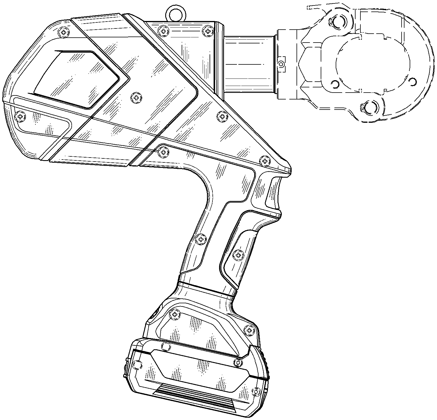
CLAIM The ornamental design for a hand-held power tool and a display on a hand-held power tool, as shown and described.
| Inventors: | Konnecke; Christoph (Frankfurt, DE), Lehr; Andreas (Neuss, DE), Frenken; Egbert (Heinsberg, DE), Bobowicz; Roman (Remscheid, DE), Darkow; Torsten (Wuppertal, DE), Jochem; Alexander (Remscheid, DE), Wilsdorf; Frank (Wermelskirchen, DE), Gimmler; Jorg (Wipperfurth, DE) | ||||||||||
|---|---|---|---|---|---|---|---|---|---|---|---|
| Applicant: |
|
||||||||||
| Assignee: | GUSTAV KLAUKE GMBH (Remscheid,
DE) |
||||||||||
| Appl. No.: | D/666,919 | ||||||||||
| Filed: | October 17, 2018 |
Related U.S. Patent Documents
| Application Number | Filing Date | Patent Number | Issue Date | ||
|---|---|---|---|---|---|
| 29608383 | Jun 21, 2017 | D834908 | |||
Foreign Application Priority Data
| Dec 22, 2016 [EM] | 001455497 | |||
| Current U.S. Class: | D8/61 |
| Current International Class: | 0805 |
| Field of Search: | ;D8/61,62,67,69 ;81/57,57.11,57.14,57.26,429,464,469 ;173/2,170,176,181 |
References Cited [Referenced By]
U.S. Patent Documents
| D657220 | April 2012 | Isobe |
| D657221 | April 2012 | Isobe et al. |
| D673829 | January 2013 | Takeshima |
| D696090 | December 2013 | Takeshima |
| D709748 | July 2014 | Frenken |
| D710173 | August 2014 | Frenken |
| D734112 | July 2015 | Herault |
| D767959 | October 2016 | Sokat |
| D767960 | October 2016 | Haneishi |
| D774858 | December 2016 | Stucki |
| D779902 | February 2017 | Sokat |
| D834908 | December 2018 | Konnecke |
| D845729 | April 2019 | Kitahara |
| D859949 | September 2019 | Wason |
Attorney, Agent or Firm: Klintworth & Rozenblat IP LLP
Description
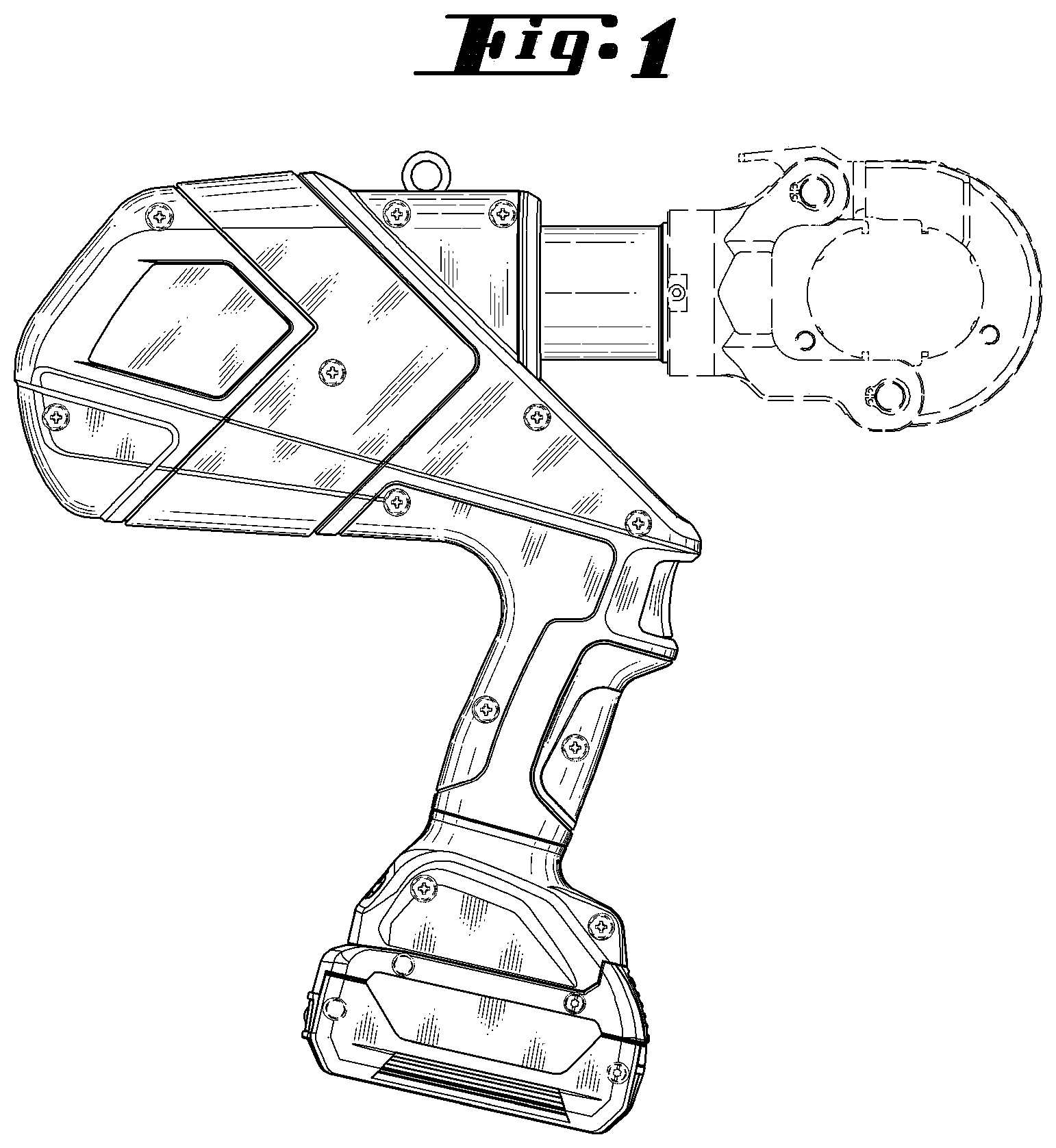
FIG. 1 is a right side elevation view of the tool in accordance with a first embodiment;
FIG. 2 is a front elevation view of the tool of FIG. 1;
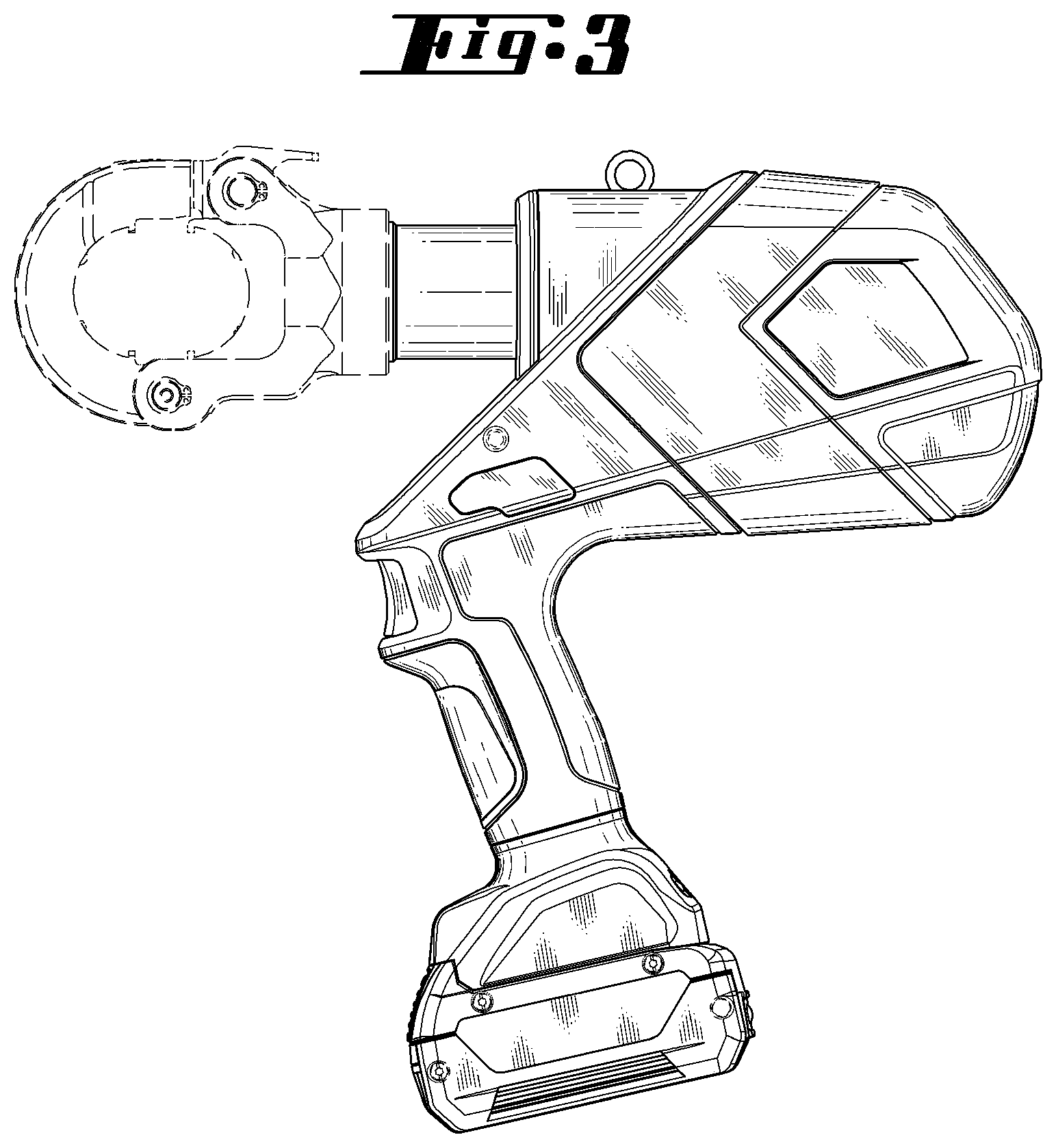
FIG. 3 is a left side elevation view of the tool of FIG. 1;
FIG. 4 is a rear elevation view of the tool of FIG. 1;
FIG. 5 is a top plan view of the tool of FIG. 1;
FIG. 6 is a bottom plan view of the tool of FIG. 1;
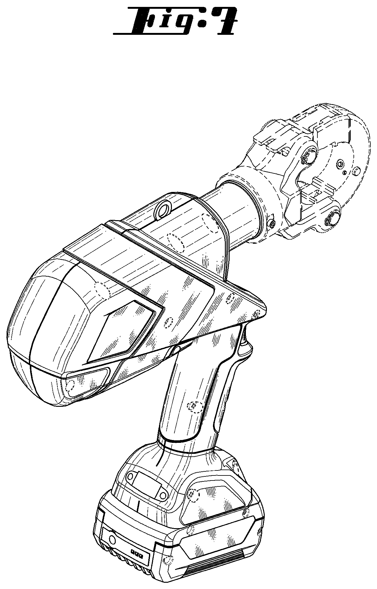
FIG. 7 is a perspective view of the tool of FIG. 1;
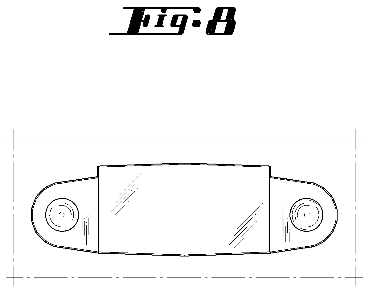
FIG. 8 is a front elevation view of the display on the tool of the first embodiment;
FIG. 9 is a right side elevation view of the tool in accordance with a second embodiment;
FIG. 10 is a front elevation view of the tool of FIG. 9;
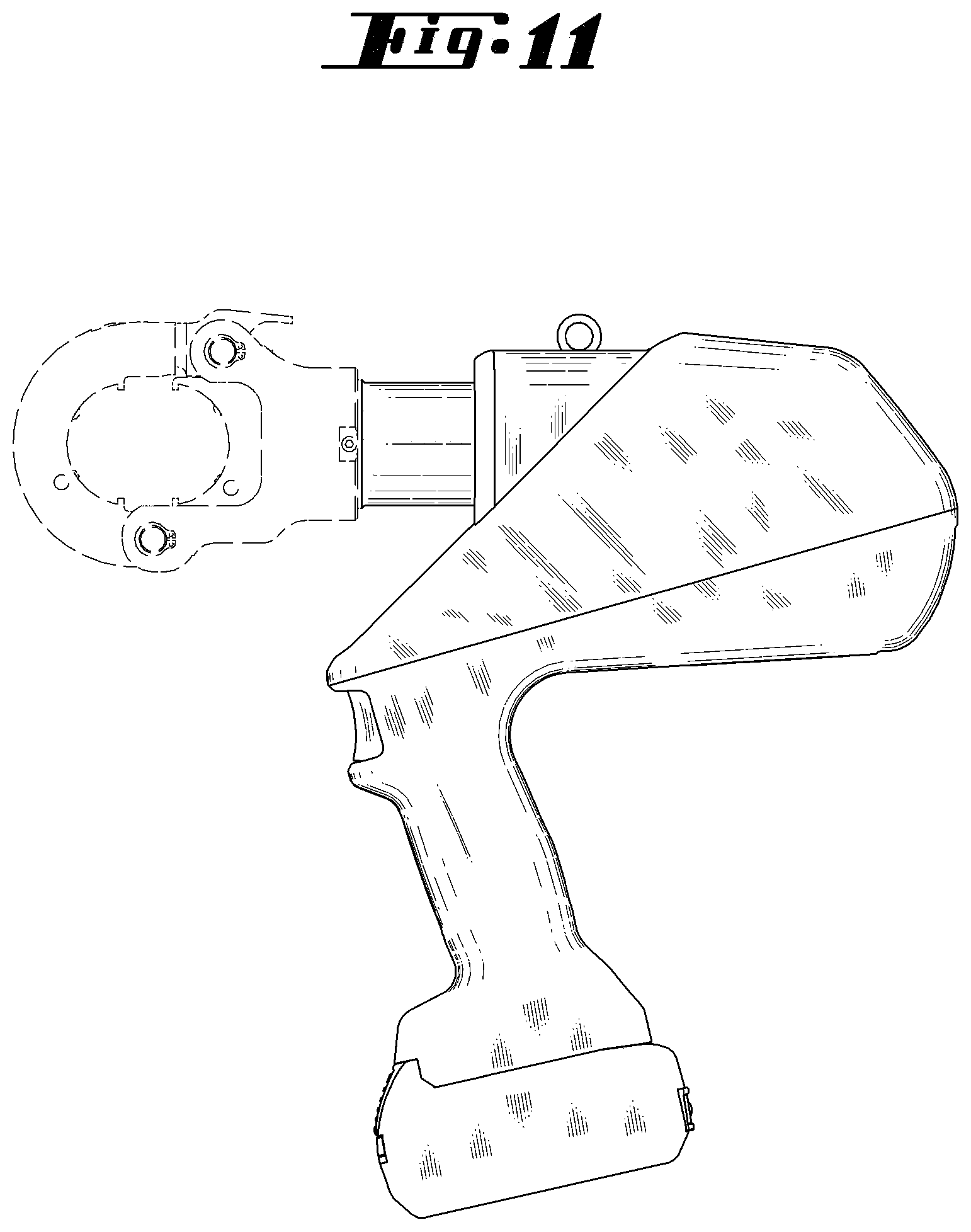
FIG. 11 is a left side elevation view of the tool of FIG. 9;
FIG. 12 is a rear elevation view of the tool of FIG. 9;
FIG. 13 is a top plan view of the tool of FIG. 9;
FIG. 14 is a bottom plan view of the tool of FIG. 9; and,
FIG. 15 is a perspective view of the tool of FIG. 9.
The elements shown in broken line in the drawings is for the purpose of showing environmental structure and forms no part of the claimed design.
* * * * *
D00000
D00001
D00002
D00003
D00004
D00005
D00006
D00007
D00008
D00009
D00010
D00011
D00012

D00013

D00014

D00015

XML
uspto.report is an independent third-party trademark research tool that is not affiliated, endorsed, or sponsored by the United States Patent and Trademark Office (USPTO) or any other governmental organization. The information provided by uspto.report is based on publicly available data at the time of writing and is intended for informational purposes only.
While we strive to provide accurate and up-to-date information, we do not guarantee the accuracy, completeness, reliability, or suitability of the information displayed on this site. The use of this site is at your own risk. Any reliance you place on such information is therefore strictly at your own risk.
All official trademark data, including owner information, should be verified by visiting the official USPTO website at www.uspto.gov. This site is not intended to replace professional legal advice and should not be used as a substitute for consulting with a legal professional who is knowledgeable about trademark law.