Firearm accessory mount
Storch Sept
U.S. patent number D896,915 [Application Number D/688,904] was granted by the patent office on 2020-09-22 for firearm accessory mount. This patent grant is currently assigned to Midwest Industries, Inc.. The grantee listed for this patent is Midwest Industries, Inc.. Invention is credited to Troy Storch.


| United States Patent | D896,915 |
| Storch | September 22, 2020 |
Firearm accessory mount
Claims
CLAIM The ornamental design for a firearm accessory mount, as shown and described.
| Inventors: | Storch; Troy (Wales, WI) | ||||||||||
|---|---|---|---|---|---|---|---|---|---|---|---|
| Applicant: |
|
||||||||||
| Assignee: | Midwest Industries, Inc.
(Waukesha, WI) |
||||||||||
| Appl. No.: | D/688,904 | ||||||||||
| Filed: | April 25, 2019 |
| Current U.S. Class: | D22/110 |
| Current International Class: | 2201 |
| Field of Search: | ;D22/100,101,103,104,108,109,110,111,115,116,199 ;D21/567,573,574 |
References Cited [Referenced By]
U.S. Patent Documents
| D247148 | February 1978 | Dicks |
| D584789 | January 2009 | Swan |
| D586875 | February 2009 | Swan |
| D588672 | March 2009 | Swan |
| D663006 | July 2012 | Storch |
| D665868 | August 2012 | Storch |
| D705888 | May 2014 | Magary |
| D716407 | October 2014 | Ferguson, II |
| D734423 | July 2015 | Borland |
| D861823 | October 2019 | Shelton |
| D864344 | October 2019 | Waters |
| 2011/0076095 | March 2011 | Storch |
| 2018/0023924 | January 2018 | Storch |
Other References
|
"Midwest Industries Red Dot mount for Ruger PC Carbine" [online]. Midwest Industries Inc. [Published on Nov. 8, 2019]. Retrieved from the Internet: <https://www.youtube.com/watch?v=SMZmvx6SDX8>. cited by examiner. |
Primary Examiner: Anwar; Khawaja
Assistant Examiner: Tehrani; Mojtaba
Attorney, Agent or Firm: Boyle Fredrickson S.C.
Description
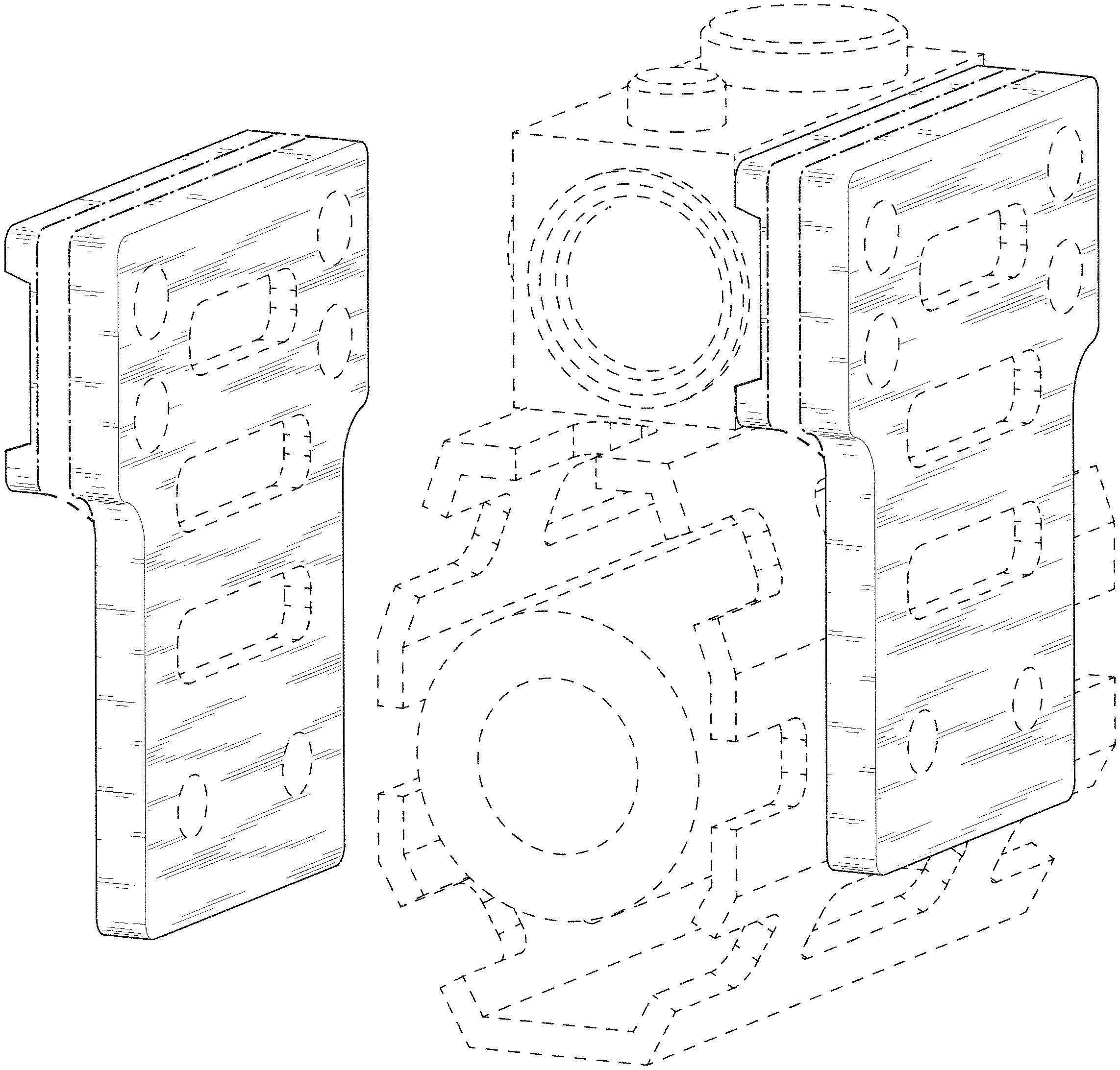
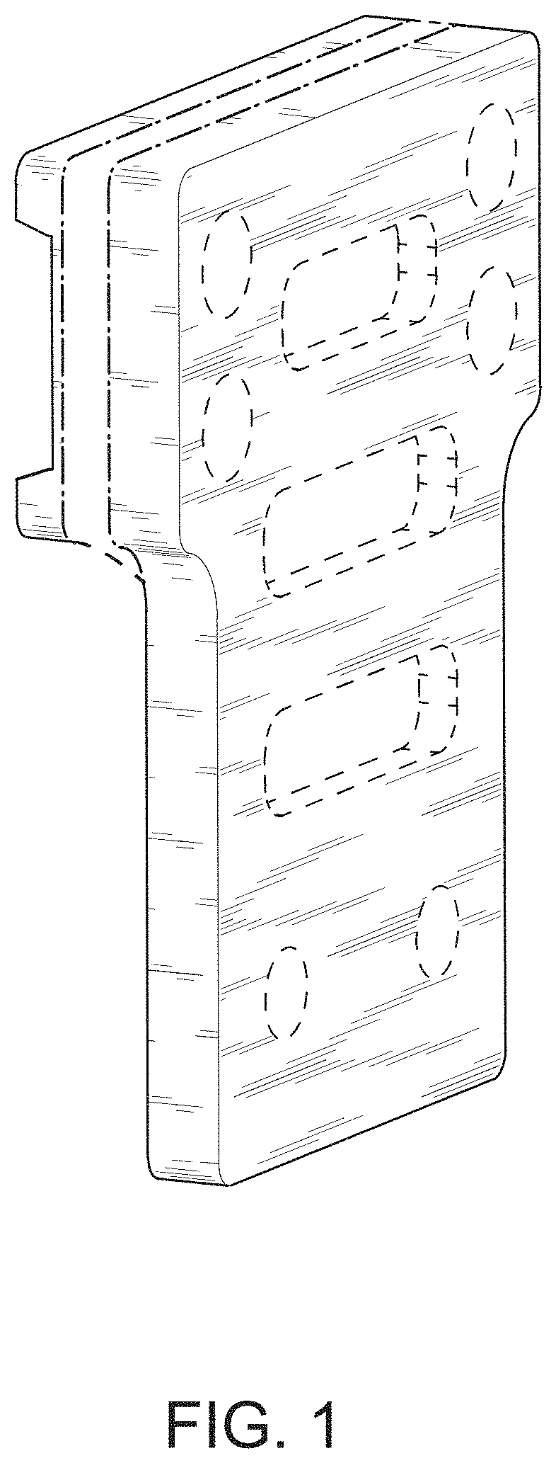
FIG. 1 is a perspective view of a firearm accessory mount incorporating my new design viewed from rearward, above, and from the right side thereof;
FIG. 2 is a front elevation view thereof;
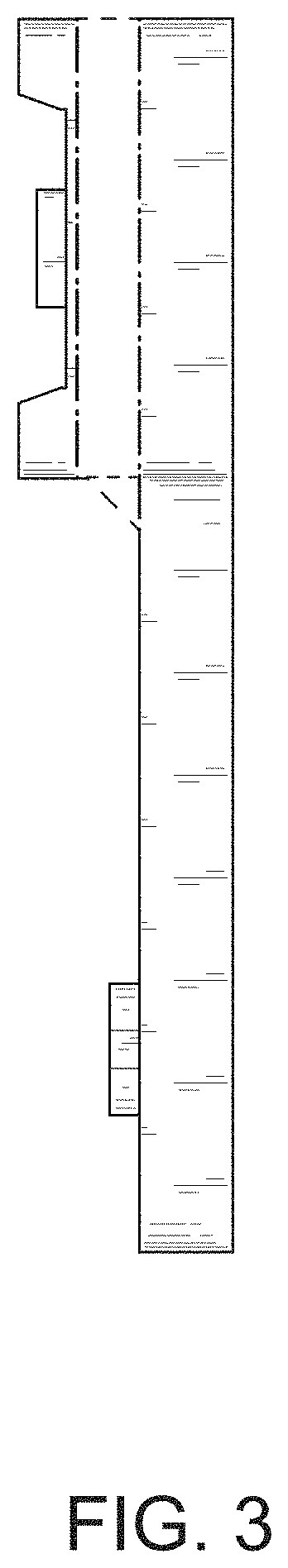
FIG. 3 is a rear elevation view thereof;
FIG. 4 is a left side elevation view thereof;
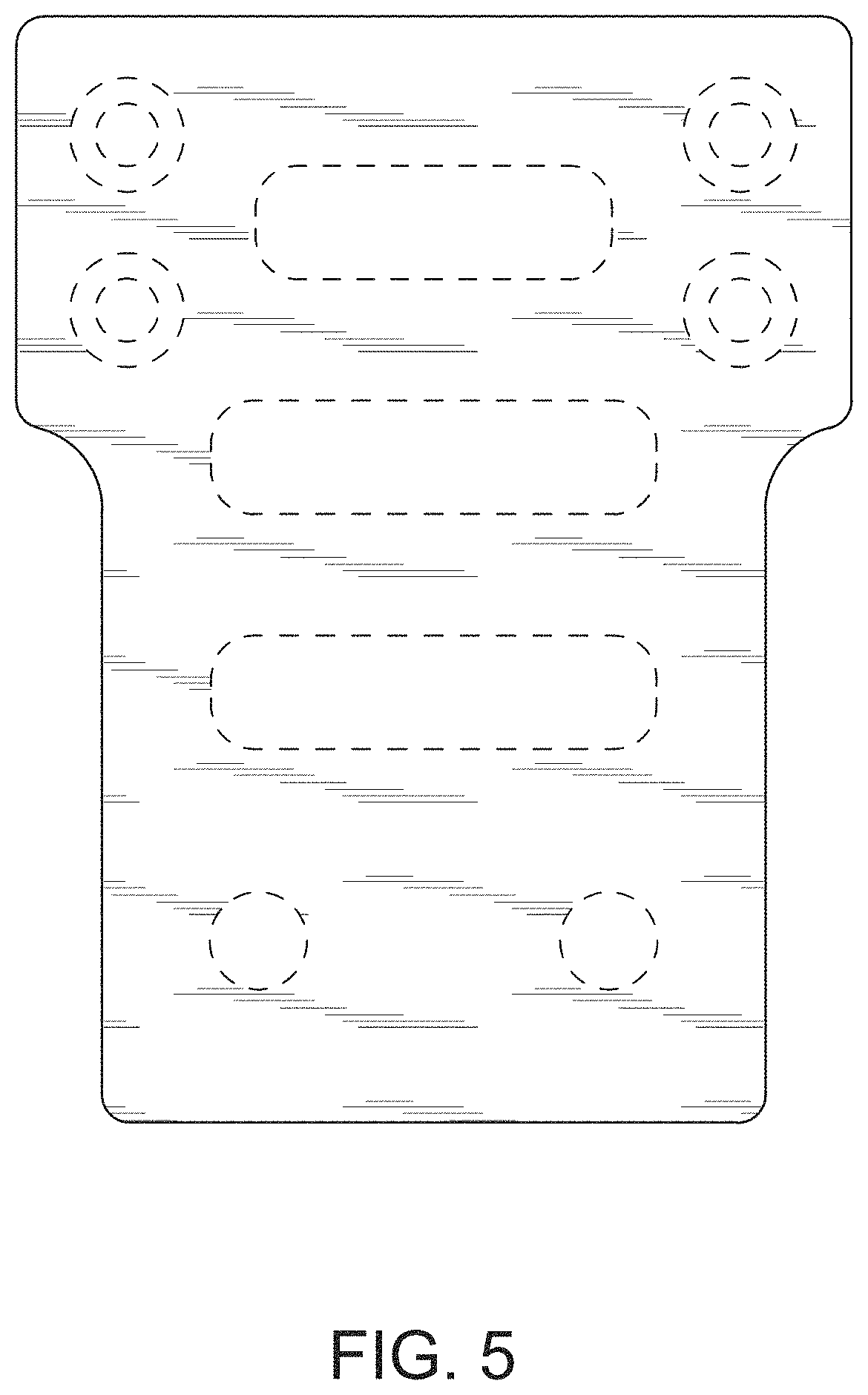
FIG. 5 is a right side elevation view thereof;
FIG. 6 is a top plan view thereof;
FIG. 7 is a bottom plan view thereof; and,
FIG. 8 is a perspective view thereof viewed from rearward, above, and from the left side thereof when associated with environment of an optic accessory and a handguard.
The uniform broken lines in FIGS. 1-8 represent environmental structures, such as an optic accessory and a handguard of a firearm, and unclaimed portions of the design and the dash-dot lines illustrate boundaries and form no part of the claimed design.
* * * * *
References
D00000
D00001
D00002
D00003
D00004
D00005
D00006
D00007
D00008
XML
uspto.report is an independent third-party trademark research tool that is not affiliated, endorsed, or sponsored by the United States Patent and Trademark Office (USPTO) or any other governmental organization. The information provided by uspto.report is based on publicly available data at the time of writing and is intended for informational purposes only.
While we strive to provide accurate and up-to-date information, we do not guarantee the accuracy, completeness, reliability, or suitability of the information displayed on this site. The use of this site is at your own risk. Any reliance you place on such information is therefore strictly at your own risk.
All official trademark data, including owner information, should be verified by visiting the official USPTO website at www.uspto.gov. This site is not intended to replace professional legal advice and should not be used as a substitute for consulting with a legal professional who is knowledgeable about trademark law.