Stub shaft
Carlini Sept
U.S. patent number D896,756 [Application Number D/637,726] was granted by the patent office on 2020-09-22 for stub shaft. This patent grant is currently assigned to Aircraft Gear Corporation. The grantee listed for this patent is Aircraft Gear Corporation. Invention is credited to Sean M. Carlini.


View All Diagrams
| United States Patent | D896,756 |
| Carlini | September 22, 2020 |
Stub shaft
Claims
CLAIM The ornamental design for a stub shaft, as shown and described.
| Inventors: | Carlini; Sean M. (Rockford, IL) | ||||||||||
|---|---|---|---|---|---|---|---|---|---|---|---|
| Applicant: |
|
||||||||||
| Assignee: | Aircraft Gear Corporation
(Loves Park, IL) |
||||||||||
| Appl. No.: | D/637,726 | ||||||||||
| Filed: | February 21, 2018 |
| Current U.S. Class: | D13/122 |
| Current International Class: | 1301 |
| Field of Search: | ;D13/112,101,113-118,122,123,133,162,184,199 ;D15/5,7,136,143,199 ;D23/209,249,365 ;D12/159,160,345,400 |
References Cited [Referenced By]
U.S. Patent Documents
| 4014184 | March 1977 | Stark |
| 4421497 | December 1983 | Federmann et al. |
| 4952195 | August 1990 | Traylor |
| D345420 | March 1994 | Stewart, Sr. |
| 5309620 | May 1994 | Shinohara et al. |
| 5601494 | February 1997 | Duggan |
| 6234907 | May 2001 | Moser |
| D470216 | February 2003 | Gustafson |
| D471623 | March 2003 | Gieseke |
| D479541 | September 2003 | Lannoch |
| 7485045 | February 2009 | Williams |
| 7682256 | March 2010 | Brace et al. |
| 8161619 | April 2012 | Wanthal |
| 8246478 | August 2012 | Schreiber et al. |
| 8430759 | April 2013 | Wanthal |
| D717420 | November 2014 | Von Seggern |
| 9056431 | June 2015 | Bond et al. |
| D767746 | September 2016 | Moredock |
| 2013/0228026 | September 2013 | Rupp |
Attorney, Agent or Firm: Daniluck; John V. Dentons Bingham Greenebaum LLP
Description
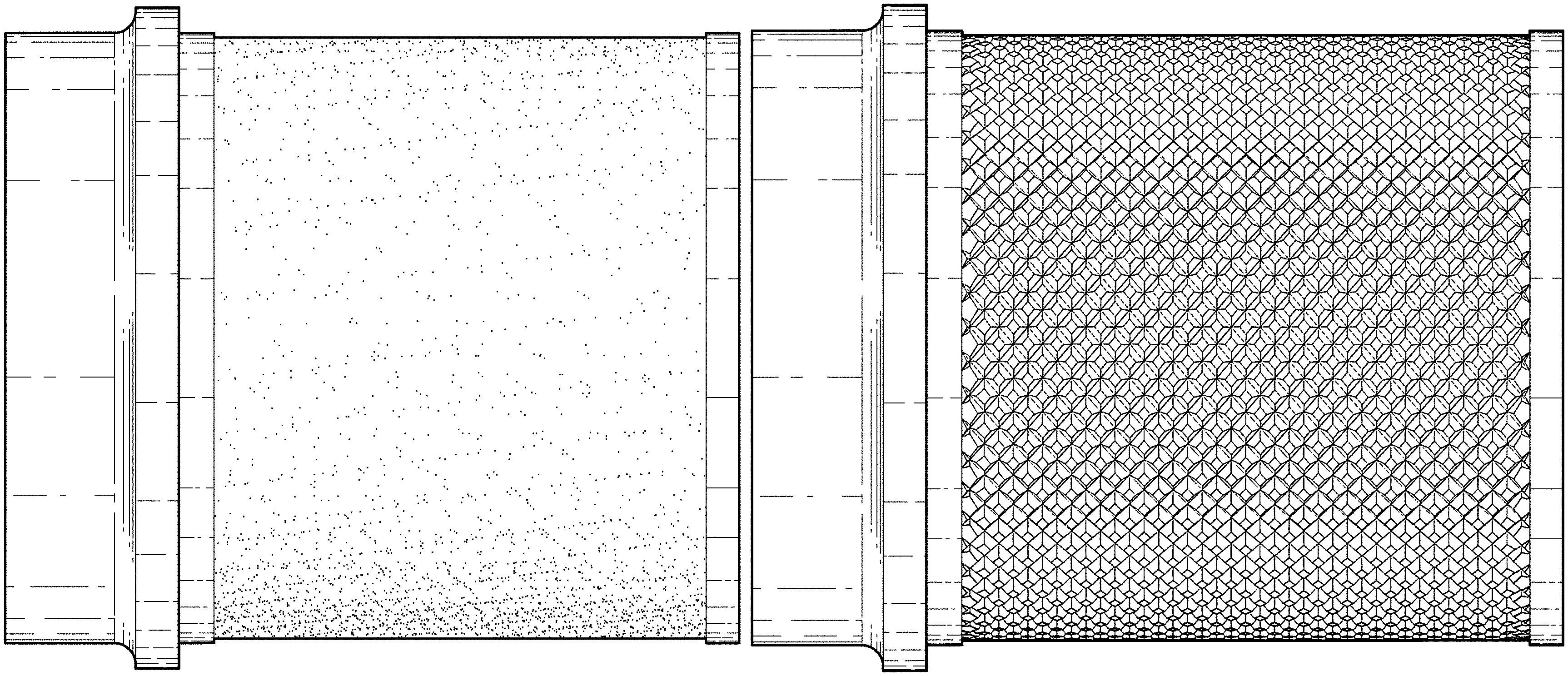
FIG. 1 is a left side elevational view of a first embodiment of a stub shaft showing my new design, the right side elevational view, top plan view, and bottom plan view being identical;
FIG. 2 is a rear end elevational view thereof;
FIG. 3 is a front end elevational view thereof;
FIG. 4 is a first perspective view thereof;
FIG. 5 is a second perspective view thereof, shown in environmental use;
FIG. 6 is a left side elevational view of a second embodiment of a stub shaft showing my new design, the right side elevational view, top plan view, and bottom plan view being identical;
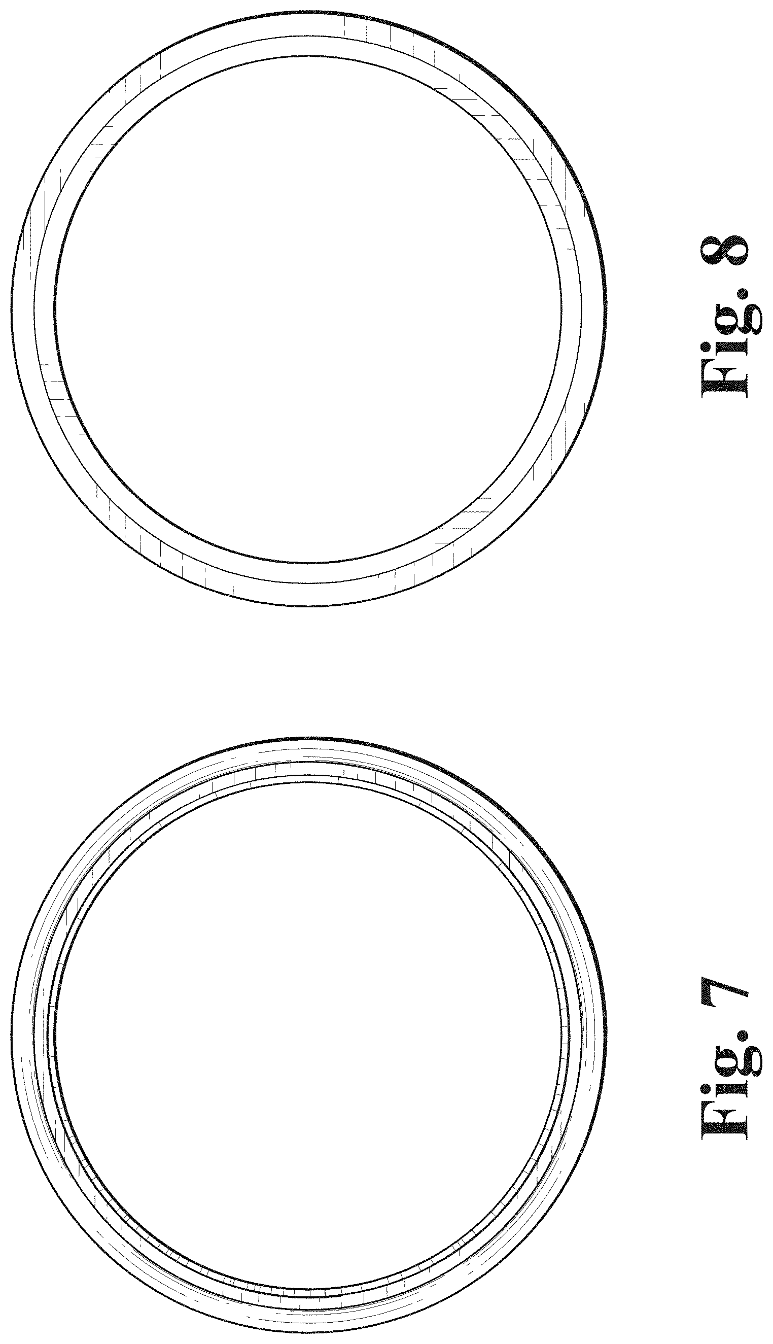
FIG. 7 is a rear end elevational view thereof;
FIG. 8 is a front end elevational view thereof;
FIG. 9 is a first perspective view thereof;
FIG. 10 is a second perspective view thereof, shown in environmental use;
FIG. 11 is a left side elevational view of a third embodiment of a stub shaft showing my new design, the right side elevational view, top plan view, and bottom plan view being identical;
FIG. 12 is a rear end elevational view thereof;
FIG. 13 is a front end elevational view thereof;
FIG. 14 is a first perspective view thereof;
FIG. 15 is a second perspective view thereof, shown in environmental use;
FIG. 16 is a left side elevational view of a fourth embodiment of a stub shaft showing my new design, the right side elevational view, top plan view, and bottom plan view being identical;
FIG. 17 is a rear end elevational view thereof;
FIG. 18 is a front end elevational view thereof;
FIG. 19 is a first perspective view thereof; and,
FIG. 20 is a second perspective view thereof, shown in environmental use.
The broken lines shown represent environmental subject matter and form no part of the claimed design.
* * * * *
D00000
D00001
D00002
D00003
D00004
D00005
D00006
D00007
D00008
D00009
D00010
D00011
D00012

D00013

D00014

D00015

D00016

XML
uspto.report is an independent third-party trademark research tool that is not affiliated, endorsed, or sponsored by the United States Patent and Trademark Office (USPTO) or any other governmental organization. The information provided by uspto.report is based on publicly available data at the time of writing and is intended for informational purposes only.
While we strive to provide accurate and up-to-date information, we do not guarantee the accuracy, completeness, reliability, or suitability of the information displayed on this site. The use of this site is at your own risk. Any reliance you place on such information is therefore strictly at your own risk.
All official trademark data, including owner information, should be verified by visiting the official USPTO website at www.uspto.gov. This site is not intended to replace professional legal advice and should not be used as a substitute for consulting with a legal professional who is knowledgeable about trademark law.