Lighting device
Hine , et al. Sept
U.S. patent number D896,422 [Application Number D/640,544] was granted by the patent office on 2020-09-15 for lighting device. This patent grant is currently assigned to Energizer Brands, LLC. The grantee listed for this patent is Energizer Brands, LLC. Invention is credited to David J. Hine, Jeffrey J. Smith.


View All Diagrams
| United States Patent | D896,422 |
| Hine , et al. | September 15, 2020 |
Lighting device
Claims
CLAIM The ornamental design for a lighting device, as shown and described.
| Inventors: | Hine; David J. (Skaneateles, NY), Smith; Jeffrey J. (Skaneateles, NY) | ||||||||||
|---|---|---|---|---|---|---|---|---|---|---|---|
| Applicant: |
|
||||||||||
| Assignee: | Energizer Brands, LLC (St.
Louis, MO) |
||||||||||
| Appl. No.: | D/640,544 | ||||||||||
| Filed: | March 15, 2018 |
| Current U.S. Class: | D26/60; D26/39 |
| Current International Class: | 2603 |
| Field of Search: | ;D26/1,24,28,37,39,41,44,50,60,61,85,102,113,138-140 |
References Cited [Referenced By]
U.S. Patent Documents
| D51972 | April 1918 | Pearson et al. |
| D51973 | April 1918 | Pearson et al. |
| 1278738 | September 1918 | Petrie |
| 1285382 | November 1918 | Renshaw |
| D131352 | February 1942 | McPherson |
| D340777 | October 1993 | Choi |
| D361633 | August 1995 | Chabria |
| D362312 | September 1995 | Chen |
| 6511214 | January 2003 | Parsons |
| D485926 | January 2004 | Campman |
| D550385 | September 2007 | Hamilton |
| D553276 | October 2007 | Campbell |
| D571492 | June 2008 | Lee |
| D580078 | November 2008 | Lee |
| D708377 | July 2014 | Osiecki et al. |
| D771853 | November 2016 | Ott |
| 2007/0222888 | September 2007 | Xiao |
Other References
|
VieVu LE3 Camera Support, dated Jul. 2, 2017, [online], [site visited Jun. 4, 2019]. Available from Internet, URL: http://www.vievu.com/le3-camera-support/ (Year: 2017). cited by examiner. |
Primary Examiner: Lee; Angela J
Assistant Examiner: Gingrich; Shawn T
Attorney, Agent or Firm: Alston & Bird LLP
Description
FIG. 1 is a front perspective view of a lighting device according to one exemplary embodiment of the present design.
FIG. 2 is a front view the lighting device of FIG. 1.
FIG. 3 is a back view of the lighting device of FIG. 1.
FIG. 4 is a left side view of the lighting device of FIG. 1.
FIG. 5 is a right side view of the lighting device of FIG. 1.
FIG. 6 is a top view of the lighting device of FIG. 1.
FIG. 7 is a bottom view of the lighting device of FIG. 1.
FIG. 8 is a rear perspective view of the lighting device of FIG. 1.
FIG. 9 is a perspective view of a lighting device according to a second exemplary embodiment of the present design.
FIG. 10 is a front view the lighting device of FIG. 9.
FIG. 11 is a back view the lighting device of FIG. 9.
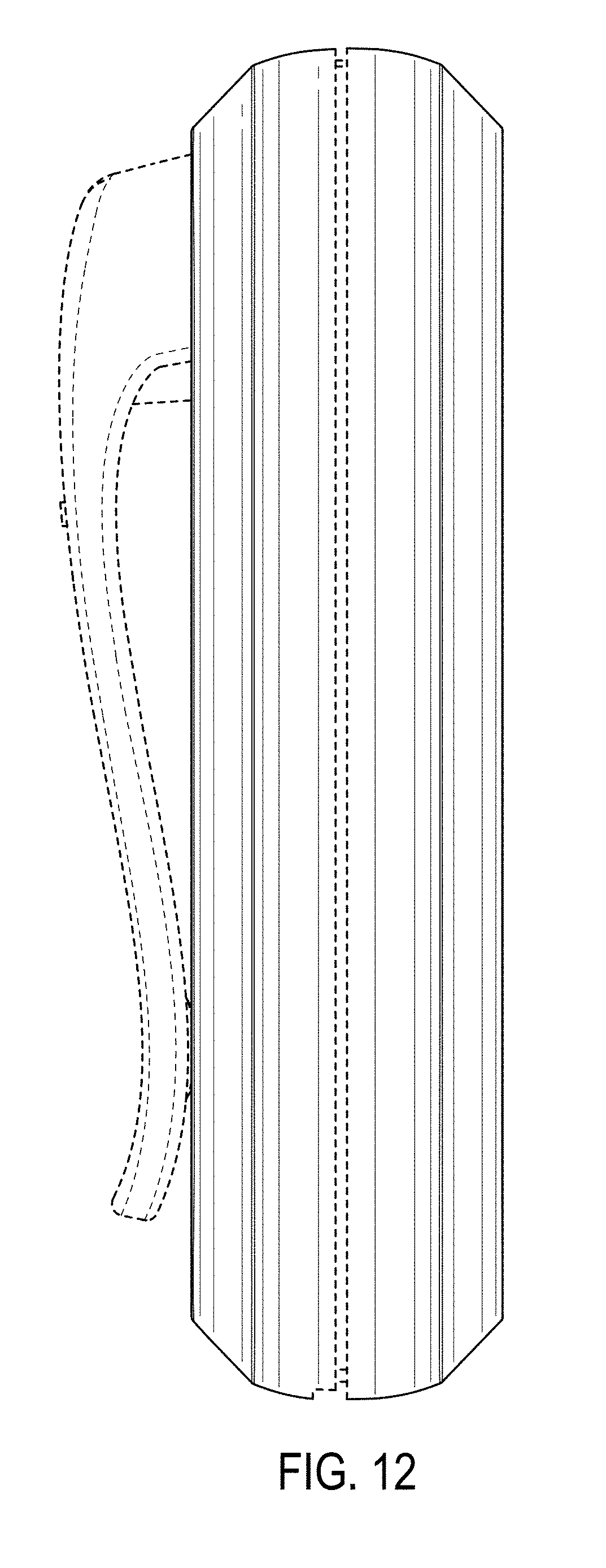
FIG. 12 is a left view the lighting device of FIG. 9.
FIG. 13 is a right view the lighting device of FIG. 9.
FIG. 14 is a top view the lighting device of FIG. 9.
FIG. 15 is a bottom view the lighting device of FIG. 9; and,
FIG. 16 is a rear perspective view of the lighting device of FIG. 9.
The broken lines shown are provided for the purpose of illustrating environmental structure and form no part of the claimed design.
* * * * *
References
D00000
D00001
D00002
D00003
D00004
D00005
D00006
D00007
D00008
D00009
D00010
D00011
D00012

D00013

D00014

XML
uspto.report is an independent third-party trademark research tool that is not affiliated, endorsed, or sponsored by the United States Patent and Trademark Office (USPTO) or any other governmental organization. The information provided by uspto.report is based on publicly available data at the time of writing and is intended for informational purposes only.
While we strive to provide accurate and up-to-date information, we do not guarantee the accuracy, completeness, reliability, or suitability of the information displayed on this site. The use of this site is at your own risk. Any reliance you place on such information is therefore strictly at your own risk.
All official trademark data, including owner information, should be verified by visiting the official USPTO website at www.uspto.gov. This site is not intended to replace professional legal advice and should not be used as a substitute for consulting with a legal professional who is knowledgeable about trademark law.