Combined measuring and dispensing device
Matusek , et al. Sept
U.S. patent number D896,077 [Application Number D/678,479] was granted by the patent office on 2020-09-15 for combined measuring and dispensing device. The grantee listed for this patent is Jack Warren Gee, II, Andrew Michael Matusek. Invention is credited to Jack Warren Gee, II, Andrew Michael Matusek.


| United States Patent | D896,077 |
| Matusek , et al. | September 15, 2020 |
Combined measuring and dispensing device
Claims
CLAIM The ornamental design for a combined measuring and dispensing device, as shown and described.
| Inventors: | Matusek; Andrew Michael (Medina, OH), Gee, II; Jack Warren (Willoughby, OH) | ||||||||||
|---|---|---|---|---|---|---|---|---|---|---|---|
| Applicant: |
|
||||||||||
| Appl. No.: | D/678,479 | ||||||||||
| Filed: | January 29, 2019 |
| Current U.S. Class: | D9/440; D9/436; D9/449 |
| Current International Class: | 0907 |
| Field of Search: | ;D3/201,202 ;D7/300,300.1,317,321,391,392,392.1,396.2,601,602,619.1,629 ;D9/434-436,439,440,443,445-447,449,452-454,499 |
References Cited [Referenced By]
U.S. Patent Documents
| 2518520 | August 1950 | Broun |
| D217759 | June 1970 | Schweickart |
| 4032050 | June 1977 | Funk |
| 5495964 | March 1996 | Santagiuliana |
| 5509582 | April 1996 | Robbins, III |
| 5873493 | February 1999 | Robinson |
| 6422426 | July 2002 | Ribbins, III et al. |
| 7090098 | August 2006 | Livingston et al. |
| 8181830 | May 2012 | Flores |
| D714584 | October 2014 | Boroski |
| 8925768 | January 2015 | Ismail |
| D741176 | October 2015 | Bell |
| D752916 | April 2016 | Goodwin |
| D763076 | August 2016 | Lane |
| D769671 | October 2016 | Bielawski |
| D772652 | November 2016 | Yao |
| D801111 | October 2017 | Eyal |
| 9828230 | November 2017 | Ismail |
| D813668 | March 2018 | Miller |
| D817084 | May 2018 | Hammer |
| D817085 | May 2018 | Davis |
| D824721 | August 2018 | Hu |
| D825332 | August 2018 | Miksovsky |
| D831414 | October 2018 | Diener |
| D843778 | March 2019 | Yao |
| D844376 | April 2019 | Rosette |
| D847563 | May 2019 | Jacobsen |
| D856067 | August 2019 | Barber |
| D858181 | September 2019 | Lown |
| D862977 | October 2019 | Bohman |
| D870509 | December 2019 | Bo |
Other References
|
Youtube. Smart Mouthwash Bottle Fills its Own 10 Millilitre Cup! by zeekzilch. Jul. 16, 2011. https://www.youtube.com/watch?v=UrHIGhN3304 (Year: 2011). cited by examiner. |
Primary Examiner: Gottschalk; Darcey E
Attorney, Agent or Firm: Jocke; Ralph E. Walker & Jocke
Description
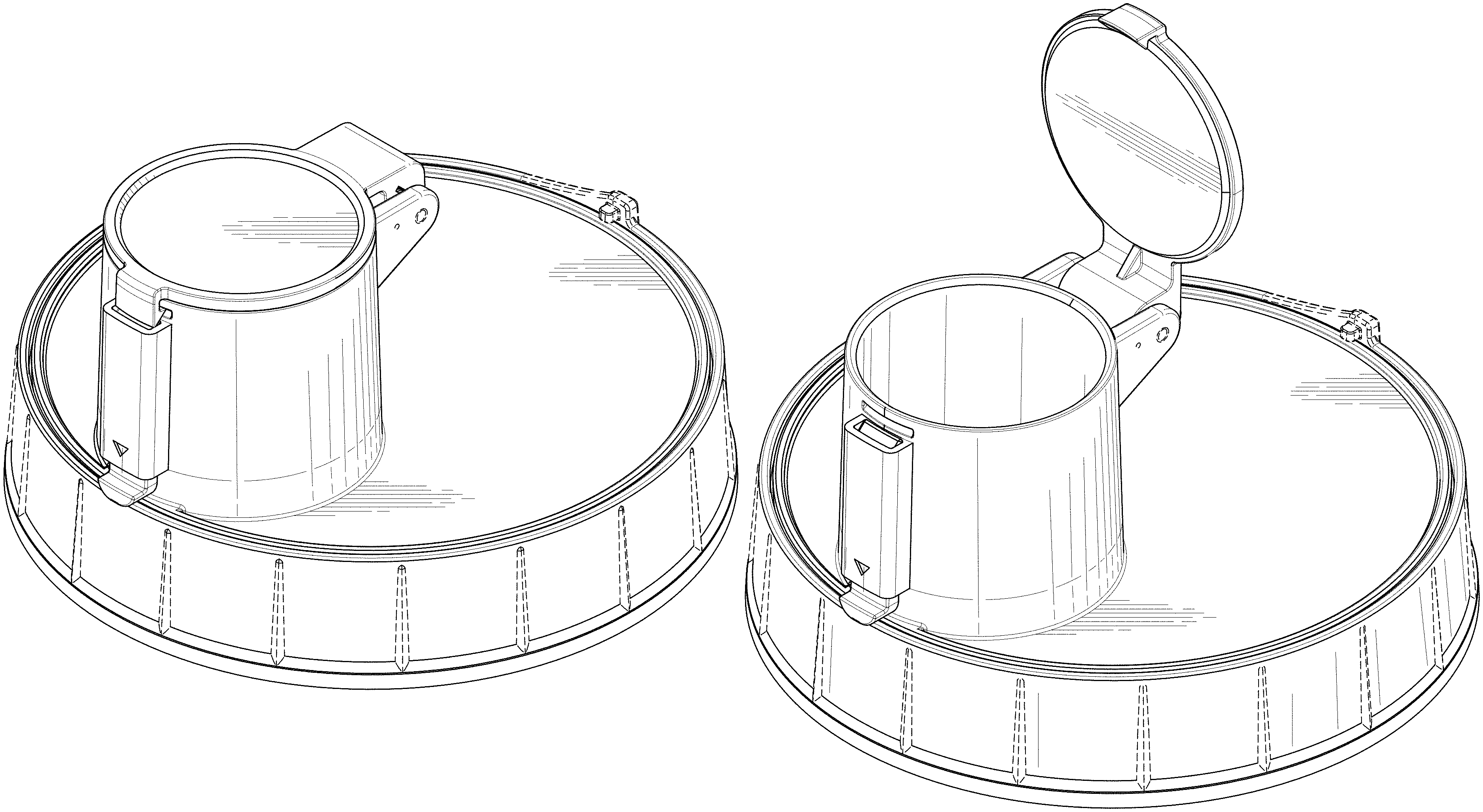
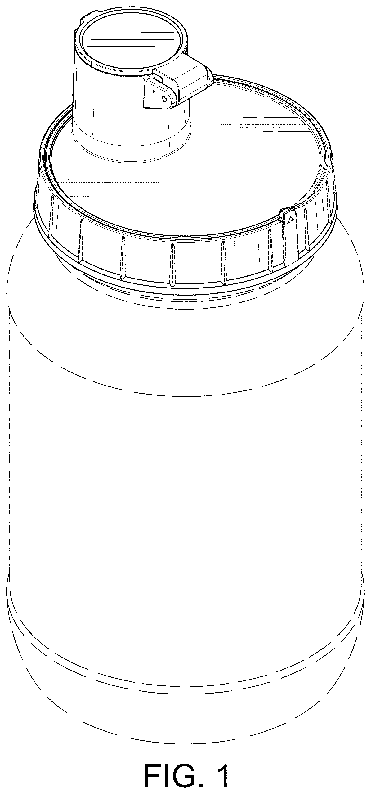
FIG. 1 is a front top left perspective view showing our new design for a combined measuring and dispensing device having a rotatable spout that is shown in a closed position.
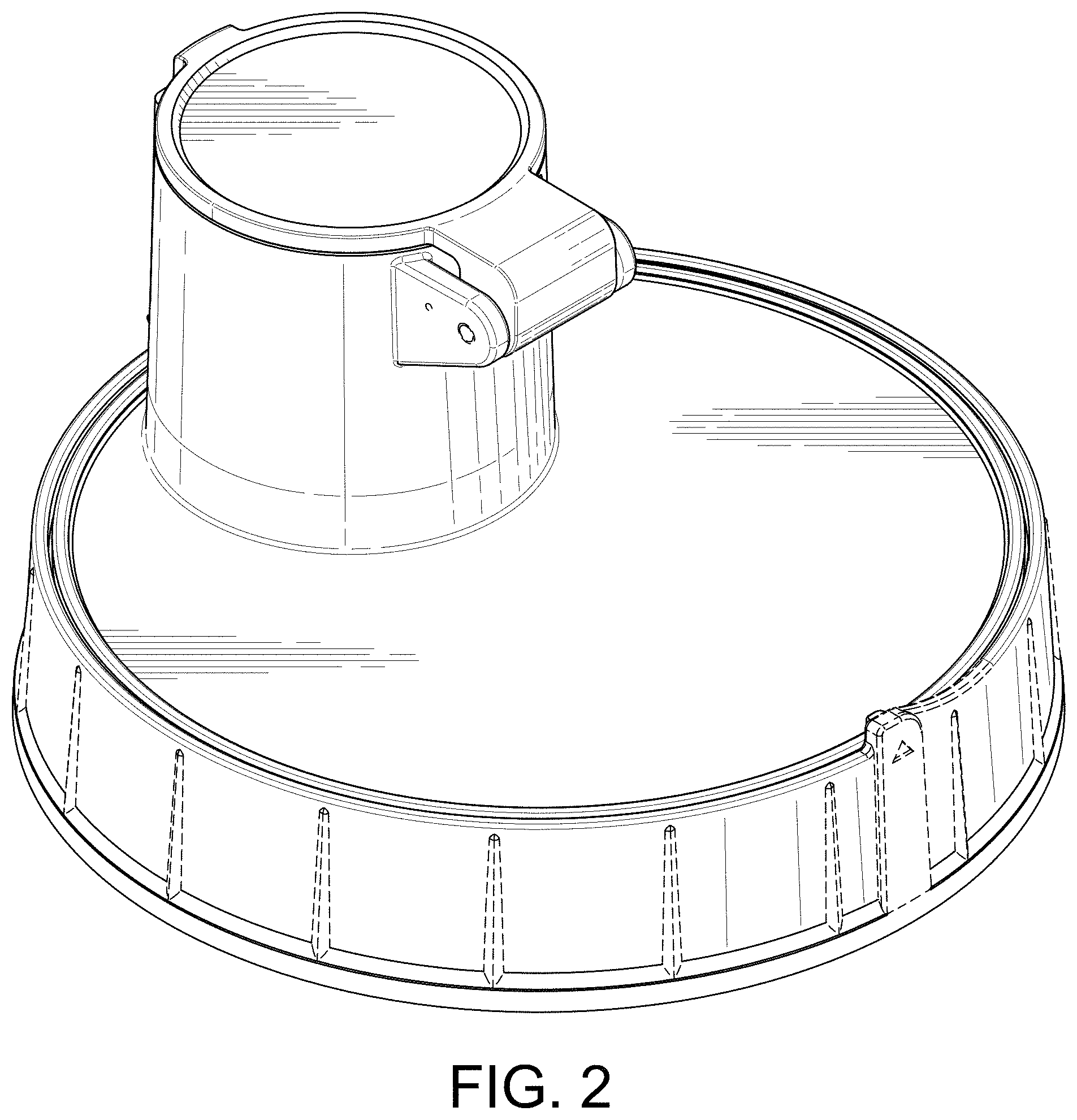
FIG. 2 is a front top left perspective view of the combined measuring and dispensing device showing the device enlarged relative to FIG. 1.
FIG. 3 is a rear top left perspective view of the combined measuring and dispensing device with the spout shown in the closed position.
FIG. 4 is a rear view of the combined measuring and dispensing device with the spout shown in the closed position.
FIG. 5 is a front view of the combined measuring and dispensing device with the spout shown in the closed position.
FIG. 6 is a left side view of the combined measuring and dispensing device with the spout shown in the closed position.
FIG. 7 is a right side view of the combined measuring and dispensing device with the spout shown in the closed position.
FIG. 8 is a top view of the combined measuring and dispensing device with the spout shown in the closed position.
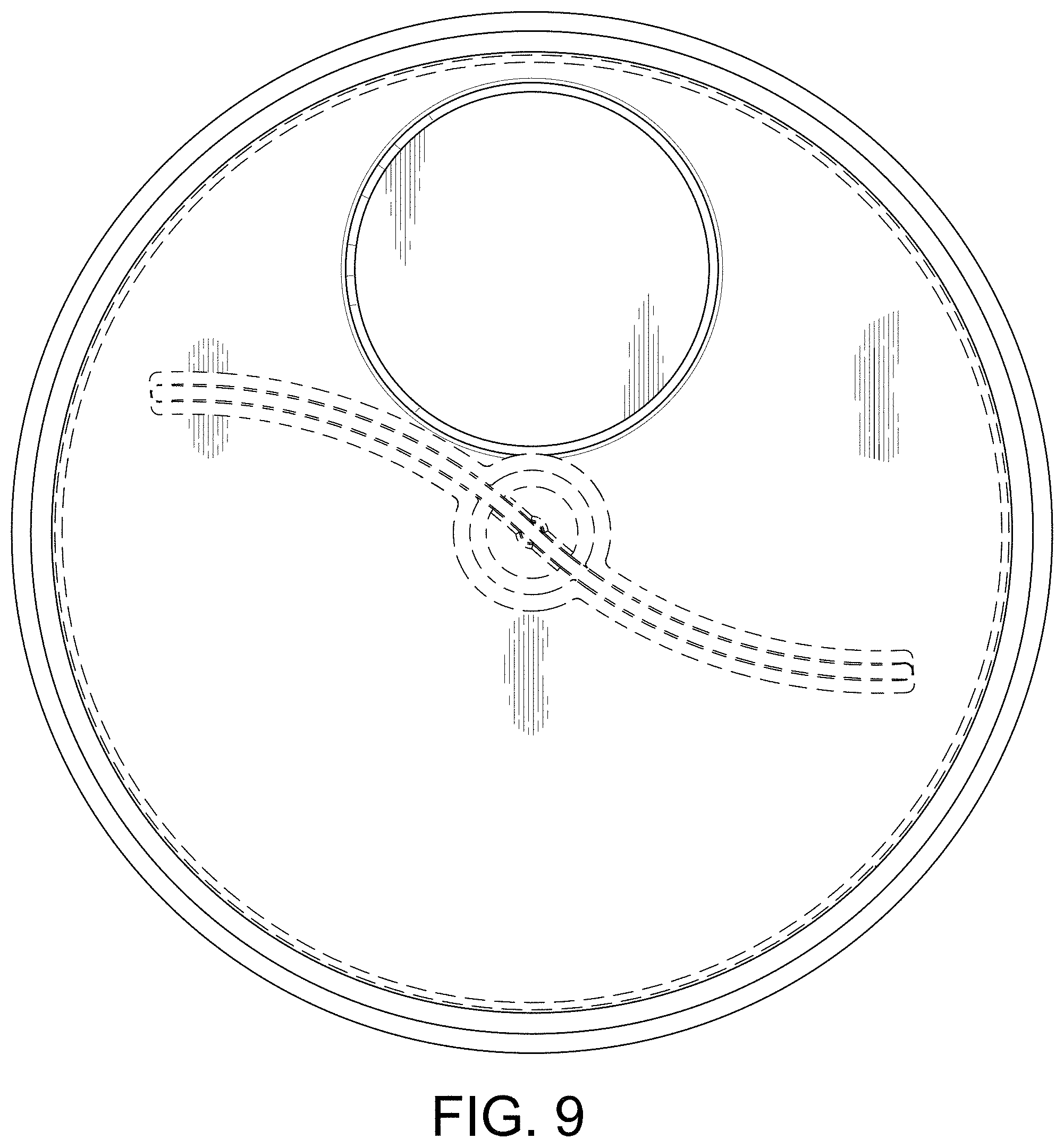
FIG. 9 is a bottom view of the combined measuring and dispensing device with the spout shown in the closed position.
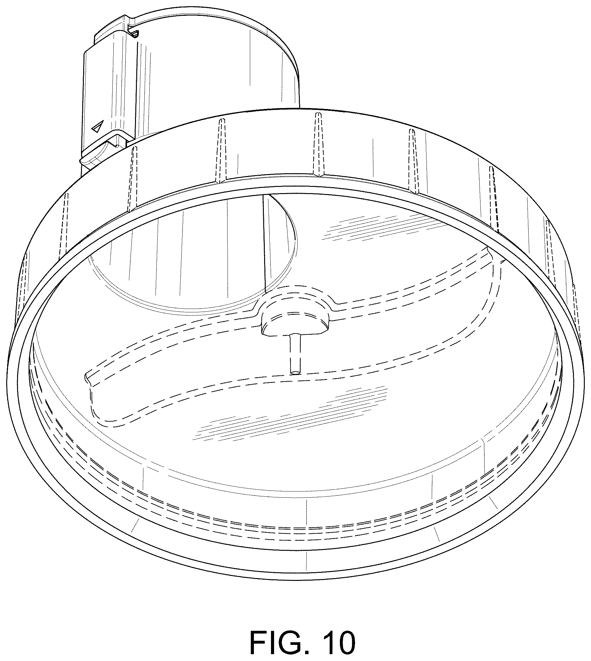
FIG. 10 is a bottom right perspective view of the combined measuring and dispensing device with the spout shown in the closed position.
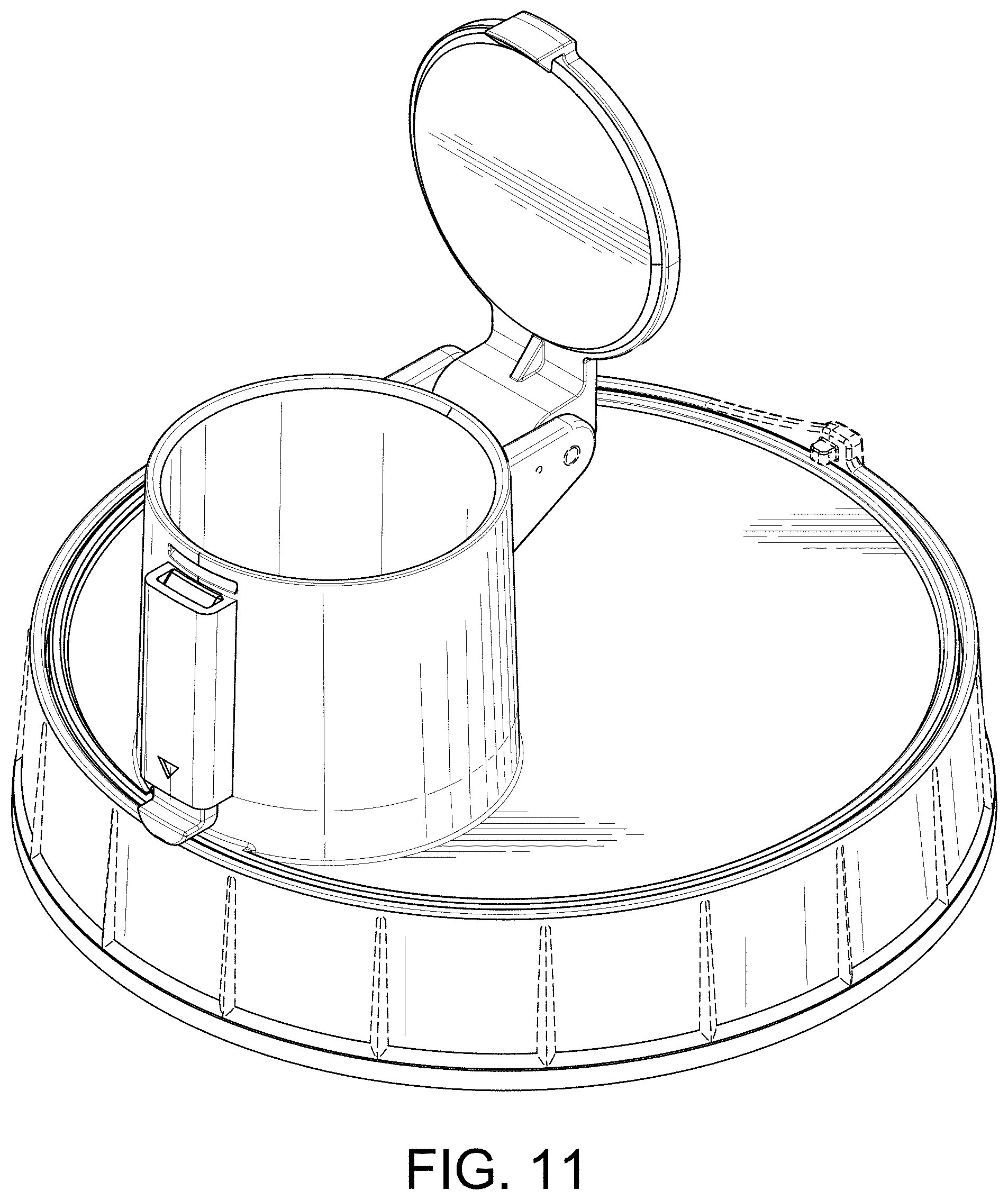
FIG. 11 is a rear top left perspective view of the combined measuring and dispensing device with the spout shown in an open position; and,
FIG. 12 is a front top left perspective view of the combined measuring and dispensing device with the spout shown in the open position.
Features shown in broken lines form no part of the claimed design.
* * * * *
References
D00000
D00001
D00002
D00003
D00004
D00005
D00006
D00007
D00008
D00009
D00010
XML
uspto.report is an independent third-party trademark research tool that is not affiliated, endorsed, or sponsored by the United States Patent and Trademark Office (USPTO) or any other governmental organization. The information provided by uspto.report is based on publicly available data at the time of writing and is intended for informational purposes only.
While we strive to provide accurate and up-to-date information, we do not guarantee the accuracy, completeness, reliability, or suitability of the information displayed on this site. The use of this site is at your own risk. Any reliance you place on such information is therefore strictly at your own risk.
All official trademark data, including owner information, should be verified by visiting the official USPTO website at www.uspto.gov. This site is not intended to replace professional legal advice and should not be used as a substitute for consulting with a legal professional who is knowledgeable about trademark law.