Firearm hand guard mount adapter
Storch Sep
U.S. patent number D895,759 [Application Number D/686,295] was granted by the patent office on 2020-09-08 for firearm hand guard mount adapter. This patent grant is currently assigned to Midwest Industries, Inc.. The grantee listed for this patent is Midwest Industries, Inc.. Invention is credited to Troy Storch.


| United States Patent | D895,759 |
| Storch | September 8, 2020 |
Firearm hand guard mount adapter
Claims
CLAIM The ornamental design for a firearm hand guard mount adapter, as shown and described.
| Inventors: | Storch; Troy (Wales, WI) | ||||||||||
|---|---|---|---|---|---|---|---|---|---|---|---|
| Applicant: |
|
||||||||||
| Assignee: | Midwest Industries, Inc.
(Waukesha, WI) |
||||||||||
| Appl. No.: | D/686,295 | ||||||||||
| Filed: | April 3, 2019 |
| Current U.S. Class: | D22/108 |
| Current International Class: | 2201 |
| Field of Search: | ;D22/108 |
References Cited [Referenced By]
U.S. Patent Documents
| 2529801 | November 1950 | Fisk |
| 2545419 | March 1951 | Platt |
| 3462021 | August 1969 | Hawke et al. |
| 3798818 | March 1974 | Casull |
| D259994 | July 1981 | Salcedo |
| D276789 | December 1984 | Olsen |
| 4751610 | June 1988 | Nickola |
| D302514 | August 1989 | Gates |
| D339374 | September 1993 | Chow et al. |
| D349230 | August 1994 | Essick |
| 5375361 | December 1994 | Rustick |
| 6499245 | December 2002 | Swan |
| D508726 | August 2005 | Storch |
| 7066059 | June 2006 | Hsieh |
| 7096620 | August 2006 | Zeh |
| 7191557 | March 2007 | Gablowski et al. |
| 7219370 | May 2007 | Teetzel |
| D556290 | November 2007 | Swan |
| 7444776 | November 2008 | Adams |
| 7552558 | June 2009 | Ballard |
| 7707762 | May 2010 | Swan |
| 7802392 | September 2010 | Peterson et al. |
| D625765 | October 2010 | Storch |
| 7836625 | November 2010 | Swan et al. |
| D657013 | April 2012 | Swan |
| D659220 | May 2012 | Foltz |
| 8201353 | June 2012 | Swan |
| 8215046 | July 2012 | Chvala |
| D666689 | September 2012 | Swan |
| D670352 | November 2012 | Norberg et al. |
| D672422 | December 2012 | Swan |
| D677048 | March 2013 | Du |
| 8424234 | April 2013 | Carlson |
| D683807 | June 2013 | Elkaim |
| 8468733 | June 2013 | Deros |
| 8510983 | August 2013 | Larue |
| 8650794 | February 2014 | Swan et al. |
| 8752320 | June 2014 | Masters |
| 8769854 | July 2014 | Battaglia |
| 8793921 | August 2014 | Tonello |
| 8806792 | August 2014 | Yan et al. |
| 8819980 | September 2014 | Geissele |
| D732378 | June 2015 | Oquendo et al. |
| 9068801 | June 2015 | Stecher et al. |
| 9091505 | July 2015 | Battaglia |
| 9157696 | October 2015 | Dextraze |
| D744459 | December 2015 | Cummings et al. |
| 9222756 | December 2015 | Battaglia et al. |
| 9239209 | January 2016 | Mayberry et al. |
| 9239210 | January 2016 | Mayberry et al. |
| 9297609 | March 2016 | Burt |
| D753256 | April 2016 | Azhocar |
| 9341441 | May 2016 | Cheng et al. |
| 9377274 | June 2016 | Kincel |
| 9404714 | August 2016 | Langevin et al. |
| 9417034 | August 2016 | Swan |
| D828898 | September 2018 | McKillips |
| D844091 | March 2019 | Kincel |
| D865111 | October 2019 | Storch |
| 2004/0000083 | January 2004 | Grant, Jr. |
| 2005/0217161 | October 2005 | Haugen et al. |
| 2006/0053673 | March 2006 | Murello |
| 2006/0174733 | June 2006 | Hsieh |
| 2008/0092422 | April 2008 | Daniel |
| 2009/0038198 | February 2009 | Yu |
| 2009/0126538 | May 2009 | Miers |
| 2010/0319231 | December 2010 | Stone |
| 2012/0167434 | July 2012 | Masters |
| 2012/0169000 | July 2012 | Lin et al. |
| 2013/0077439 | March 2013 | Larue |
| 2013/0219765 | August 2013 | Ibarguren |
| 2013/0288743 | October 2013 | Hunt |
| 2014/0041273 | February 2014 | Masters |
| 2014/0130390 | May 2014 | Geissele |
| 2014/0373419 | December 2014 | Leclair |
| 2015/0020429 | January 2015 | Savoy |
| 2015/0343627 | December 2015 | Hensley |
| 2015/0369555 | December 2015 | Daniel |
| 2016/0223286 | August 2016 | Scorch |
| 2018/0356181 | December 2018 | Williams |
Attorney, Agent or Firm: Boyle Fredrickson S.C.
Description
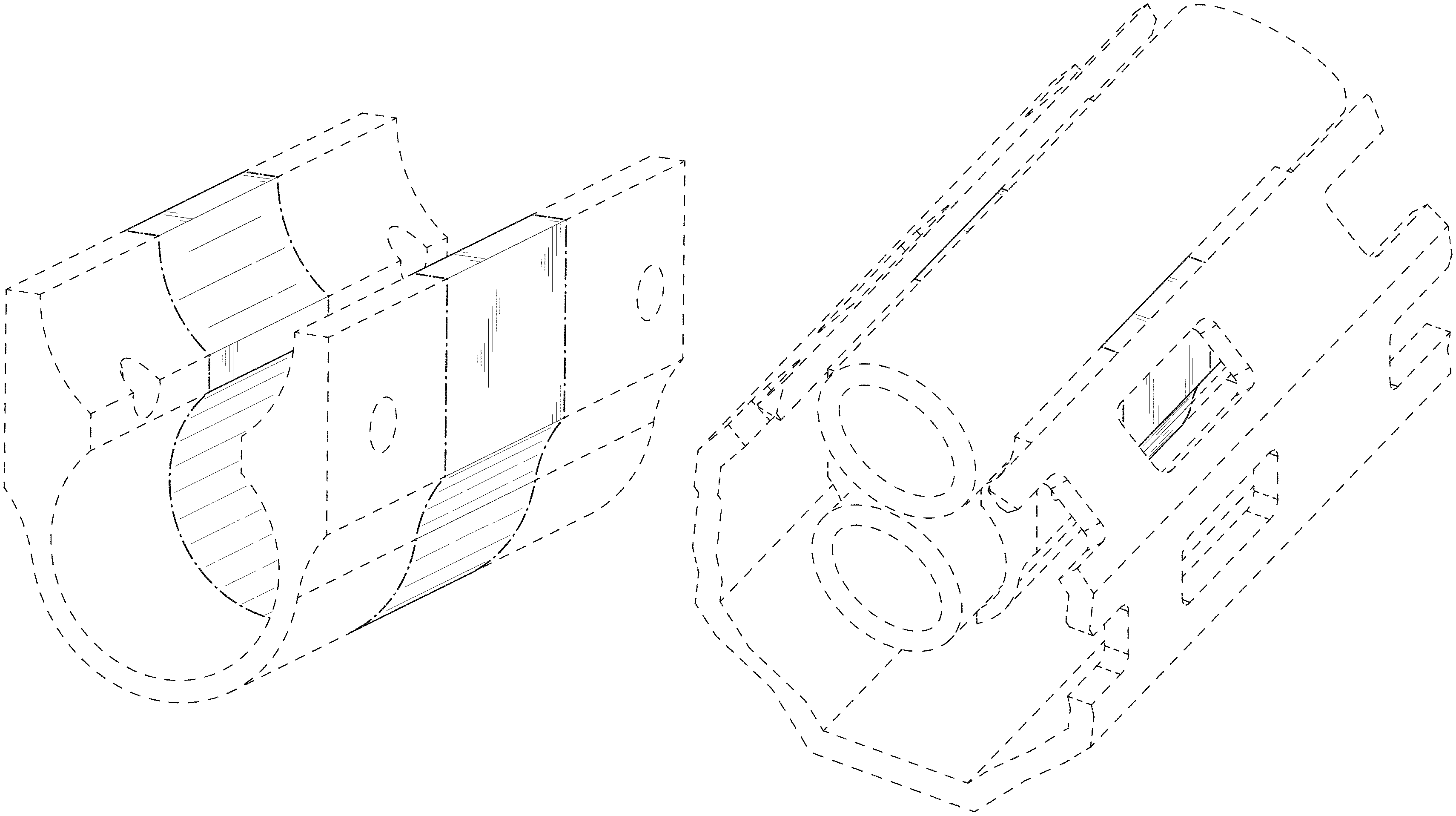
FIG. 1 is a perspective view of a firearm hand guard mount adapter incorporating my new design viewed from rearward, above, and from a left side thereof;
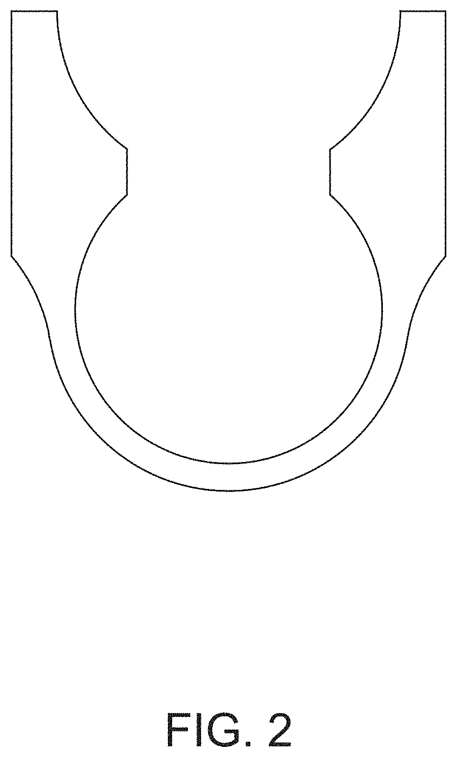
FIG. 2 is a rear elevation view thereof;
FIG. 3 is a front elevation view thereof;
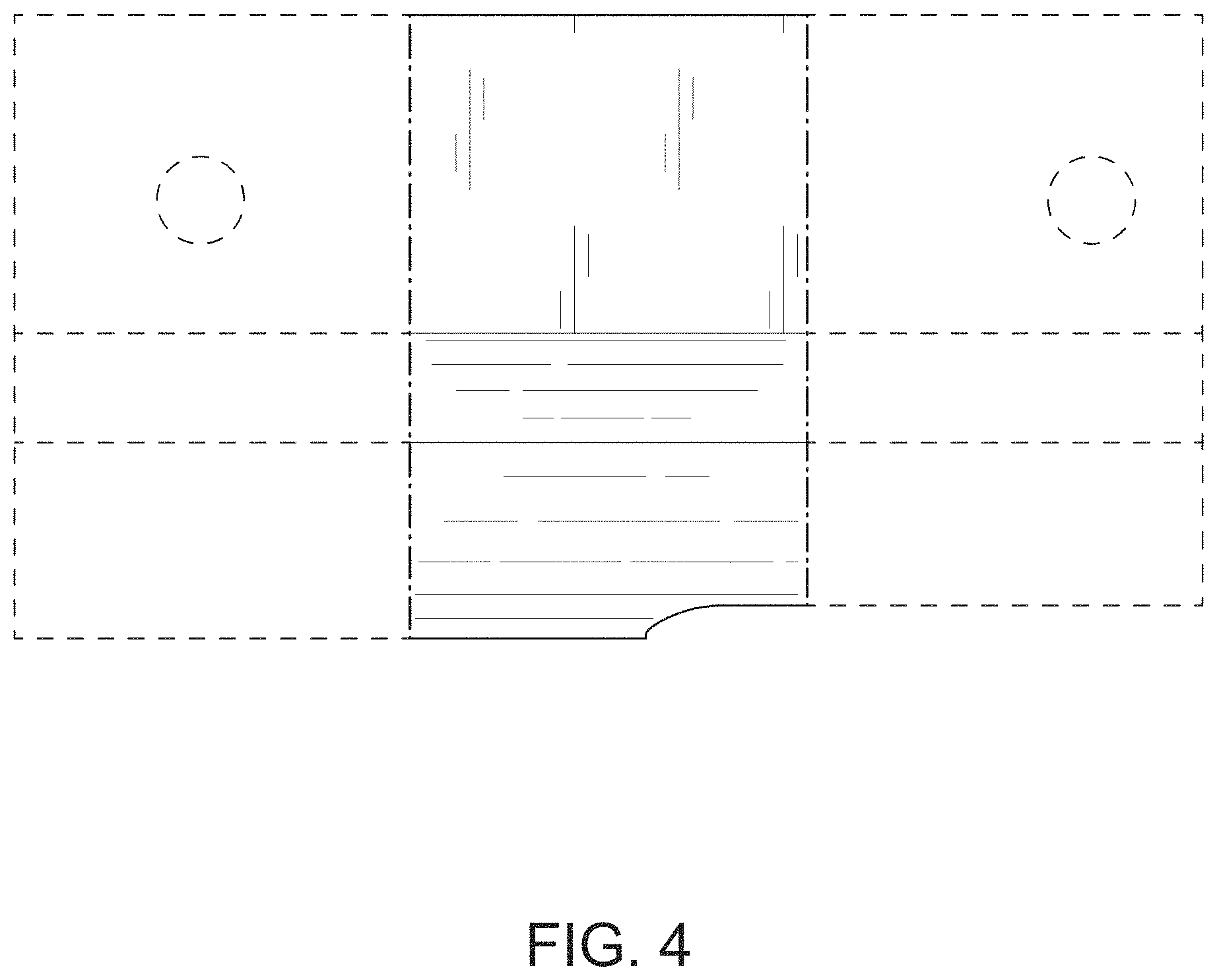
FIG. 4 is a left side elevation view thereof;
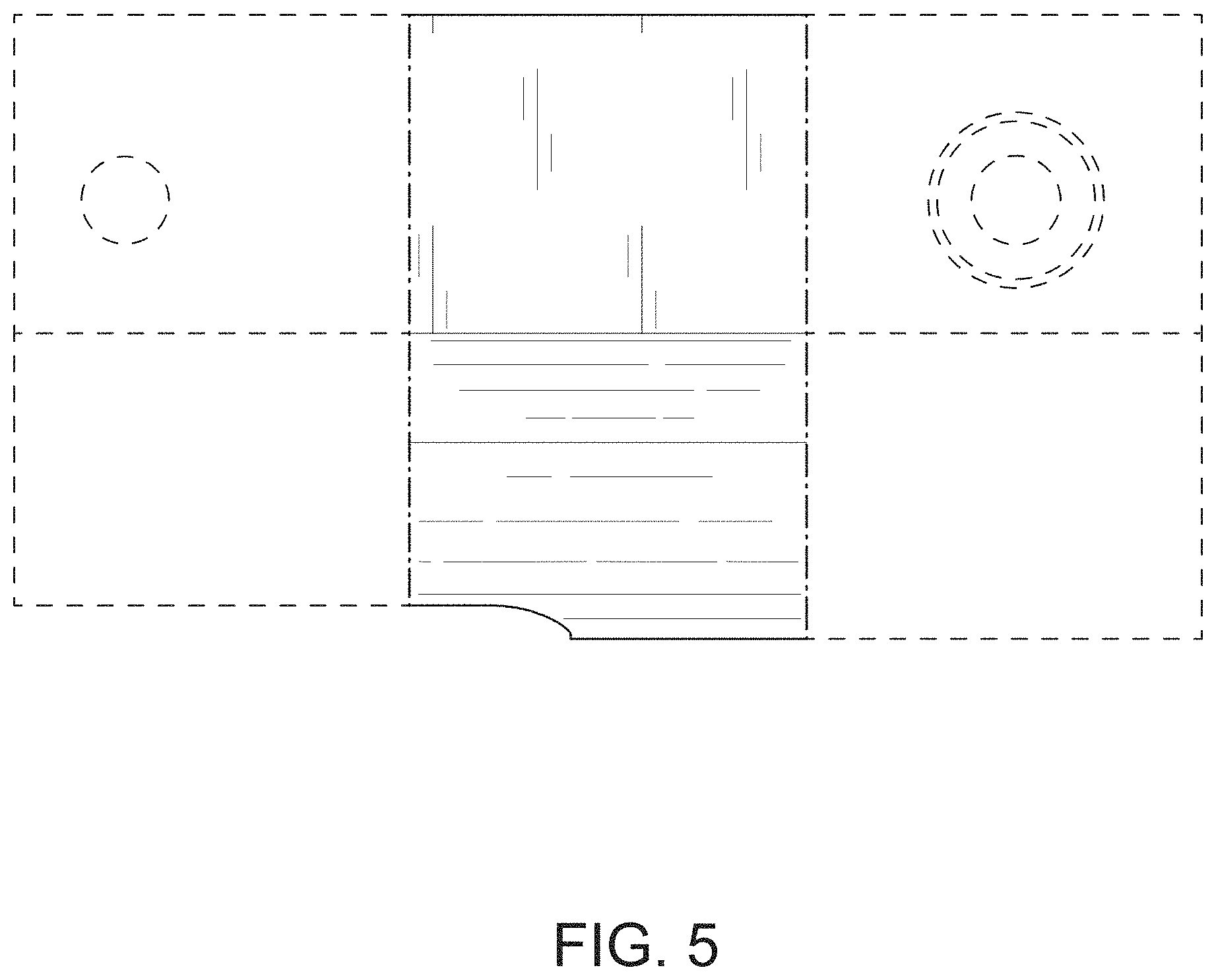
FIG. 5 is a right side elevation view thereof;
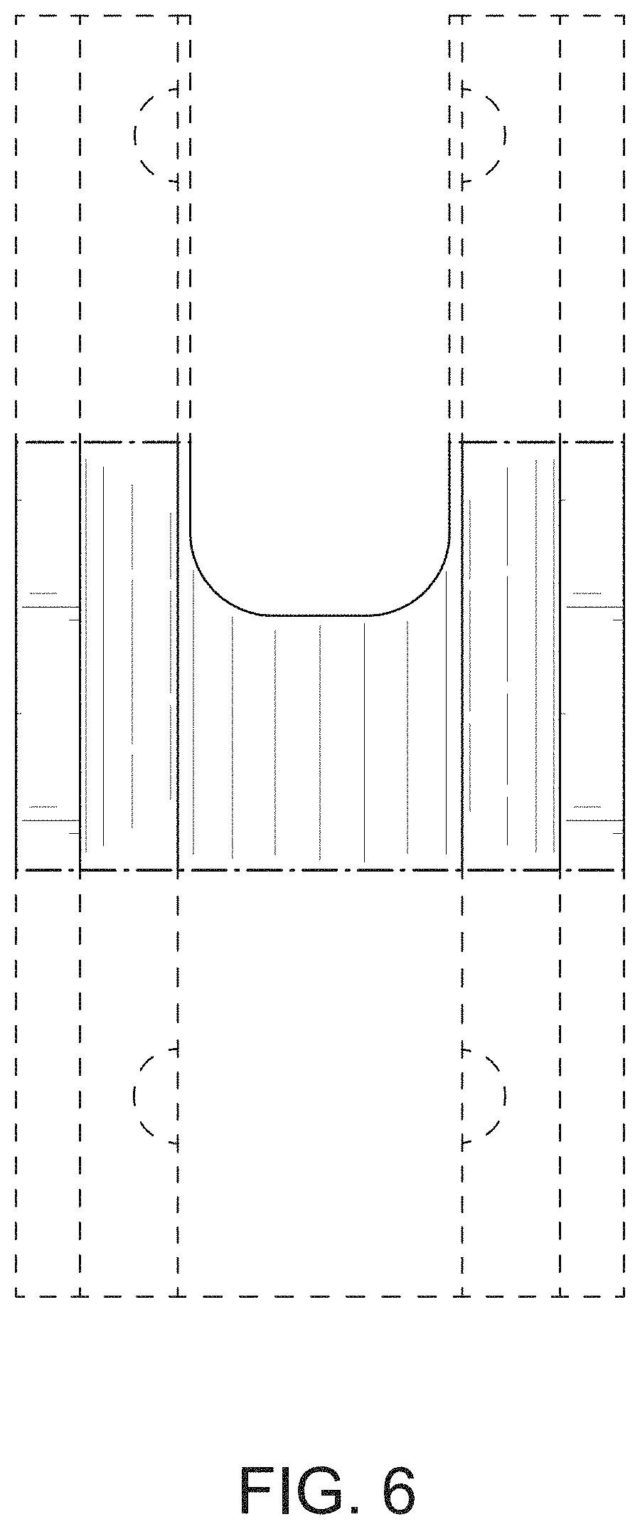
FIG. 6 is a top plan view thereof;
FIG. 7 is a bottom plan view thereof; and,
FIG. 8 is a perspective view thereof in its use environment.
The uniform broken lines in FIGS. 1-8 represent unclaimed portions of the design and environmental structures, such as the barrel of a firearm and a handguard, and the dash-dot lines illustrate boundaries and form no part of the claimed design.
* * * * *
D00000
D00001
D00002
D00003
D00004
D00005
D00006
D00007
D00008
XML
uspto.report is an independent third-party trademark research tool that is not affiliated, endorsed, or sponsored by the United States Patent and Trademark Office (USPTO) or any other governmental organization. The information provided by uspto.report is based on publicly available data at the time of writing and is intended for informational purposes only.
While we strive to provide accurate and up-to-date information, we do not guarantee the accuracy, completeness, reliability, or suitability of the information displayed on this site. The use of this site is at your own risk. Any reliance you place on such information is therefore strictly at your own risk.
All official trademark data, including owner information, should be verified by visiting the official USPTO website at www.uspto.gov. This site is not intended to replace professional legal advice and should not be used as a substitute for consulting with a legal professional who is knowledgeable about trademark law.