Optical sight
Crispin , et al. Sep
U.S. patent number D895,051 [Application Number D/657,518] was granted by the patent office on 2020-09-01 for optical sight. This patent grant is currently assigned to LEUPOLD & STEVENS, INC.. The grantee listed for this patent is LEUPOLD & STEVENS, INC.. Invention is credited to Quint Crispin, Matt Davis.


View All Diagrams
| United States Patent | D895,051 |
| Crispin , et al. | September 1, 2020 |
Optical sight
Claims
CLAIM The ornamental design for an optical sight, as shown and described.
| Inventors: | Crispin; Quint (Beaverton, OR), Davis; Matt (Beaverton, OR) | ||||||||||
|---|---|---|---|---|---|---|---|---|---|---|---|
| Applicant: |
|
||||||||||
| Assignee: | LEUPOLD & STEVENS, INC.
(Beaverton, OR) |
||||||||||
| Family ID: | 72192886 | ||||||||||
| Appl. No.: | D/657,518 | ||||||||||
| Filed: | July 23, 2018 |
Related U.S. Patent Documents
| Application Number | Filing Date | Patent Number | Issue Date | ||
|---|---|---|---|---|---|
| 15405186 | Jan 12, 2017 | ||||
| Current U.S. Class: | D22/109 |
| Current CPC Class: | H04L41/0896 20130101; H04L67/34 20130101; H04L41/5022 20130101; H04L67/1097 20130101; H04L67/06 20130101; H04L67/2833 20130101 |
| Current International Class: | 2201 |
| Field of Search: | ;D22/109 |
References Cited [Referenced By]
U.S. Patent Documents
| 4417814 | November 1983 | Doliber |
| 4863269 | September 1989 | Ellis |
| 6327806 | December 2001 | Paige |
| 6516551 | February 2003 | Gaber |
| 7355790 | April 2008 | Wagner et al. |
| D612756 | March 2010 | D'Amelio |
| D742991 | November 2015 | Klecker |
| D747431 | January 2016 | Cheng |
| 9453706 | September 2016 | Crispin |
| D784480 | April 2017 | Oz |
| D837927 | January 2019 | Trulsson |
| 2015/0198421 | July 2015 | Crispin |
| 2015/0241175 | August 2015 | Wolf |
| 2016/0102943 | April 2016 | Teetzel |
Attorney, Agent or Firm: McCoy Russell LLP
Description
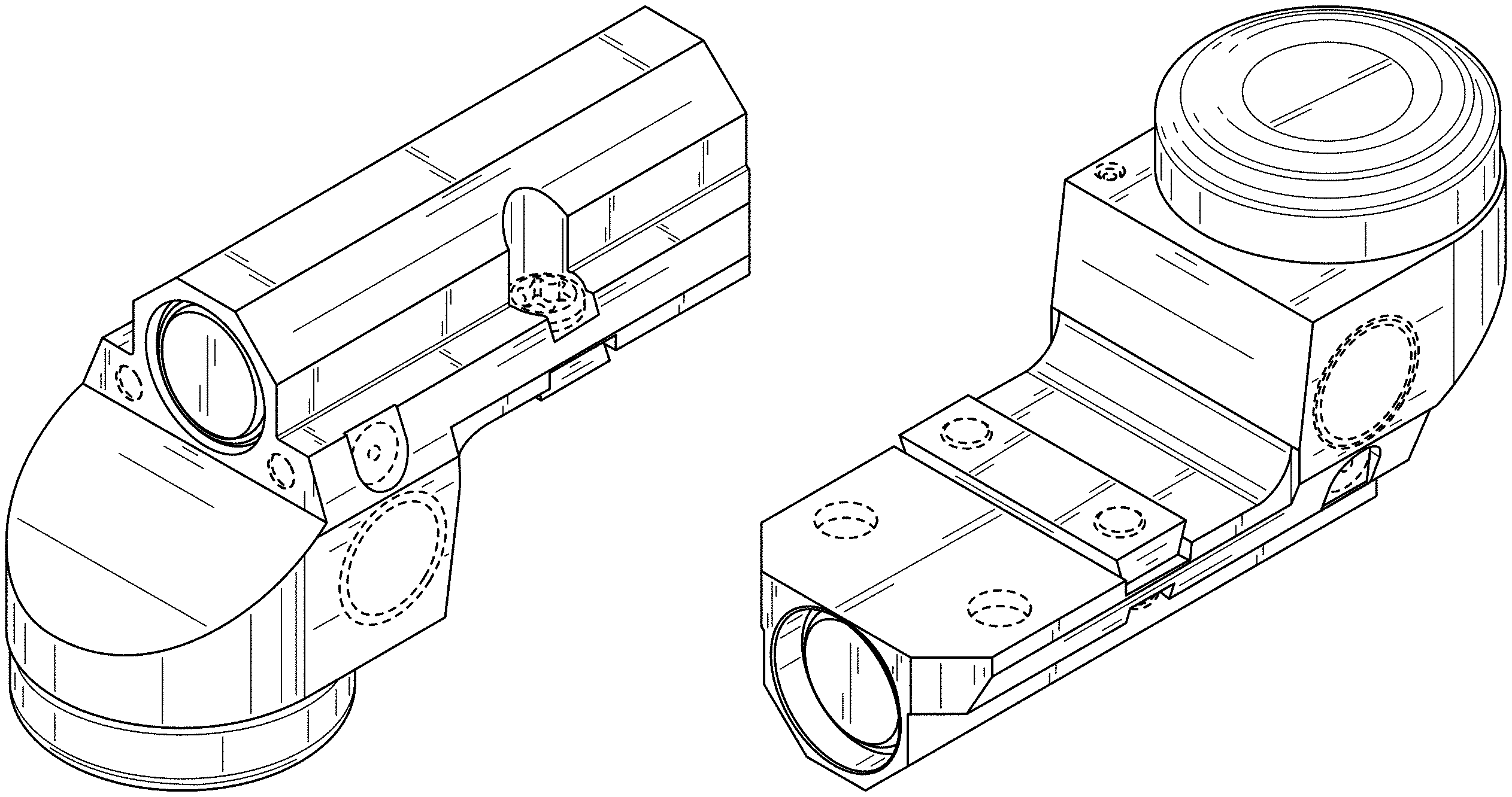
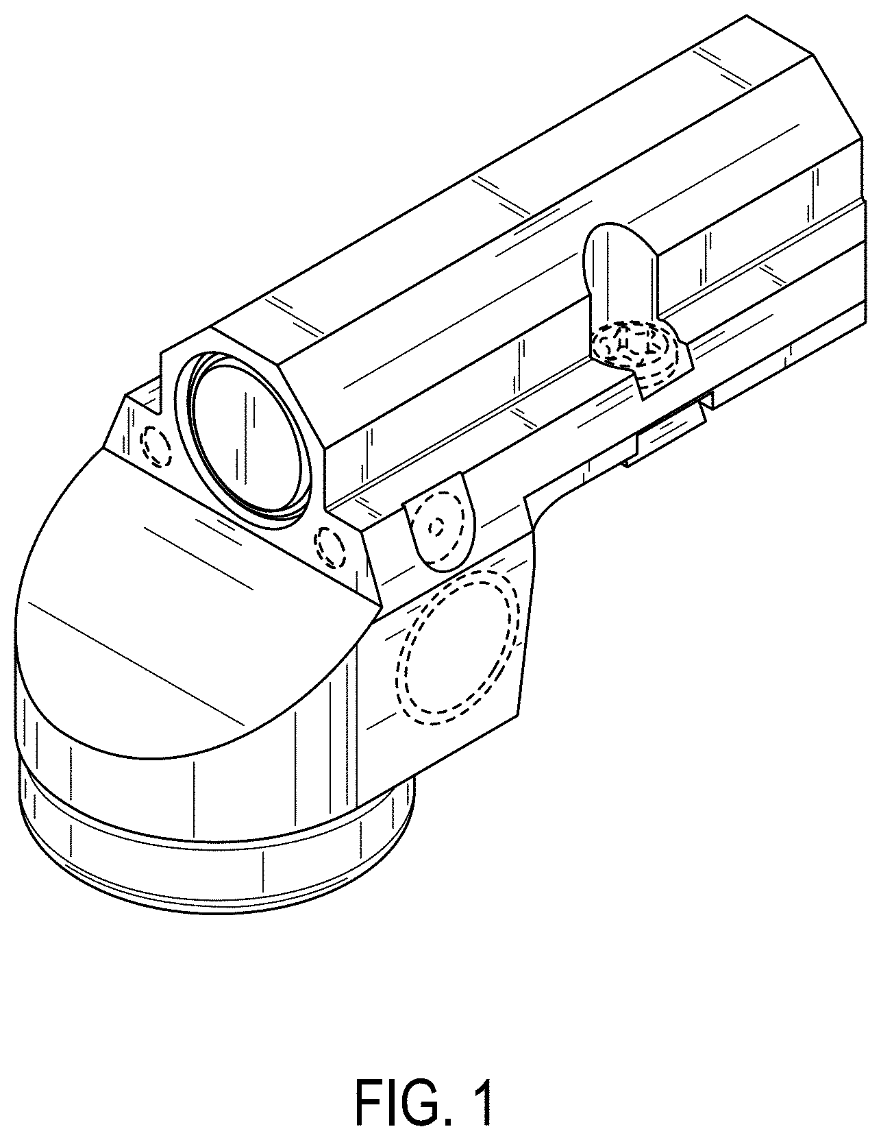
FIG. 1 is a top-right-rear perspective view of an optical sight according to the present invention.
FIG. 2 is a top-left-front perspective view of the optical sight.
FIG. 3 is a bottom-right-front perspective view of the optical sight.
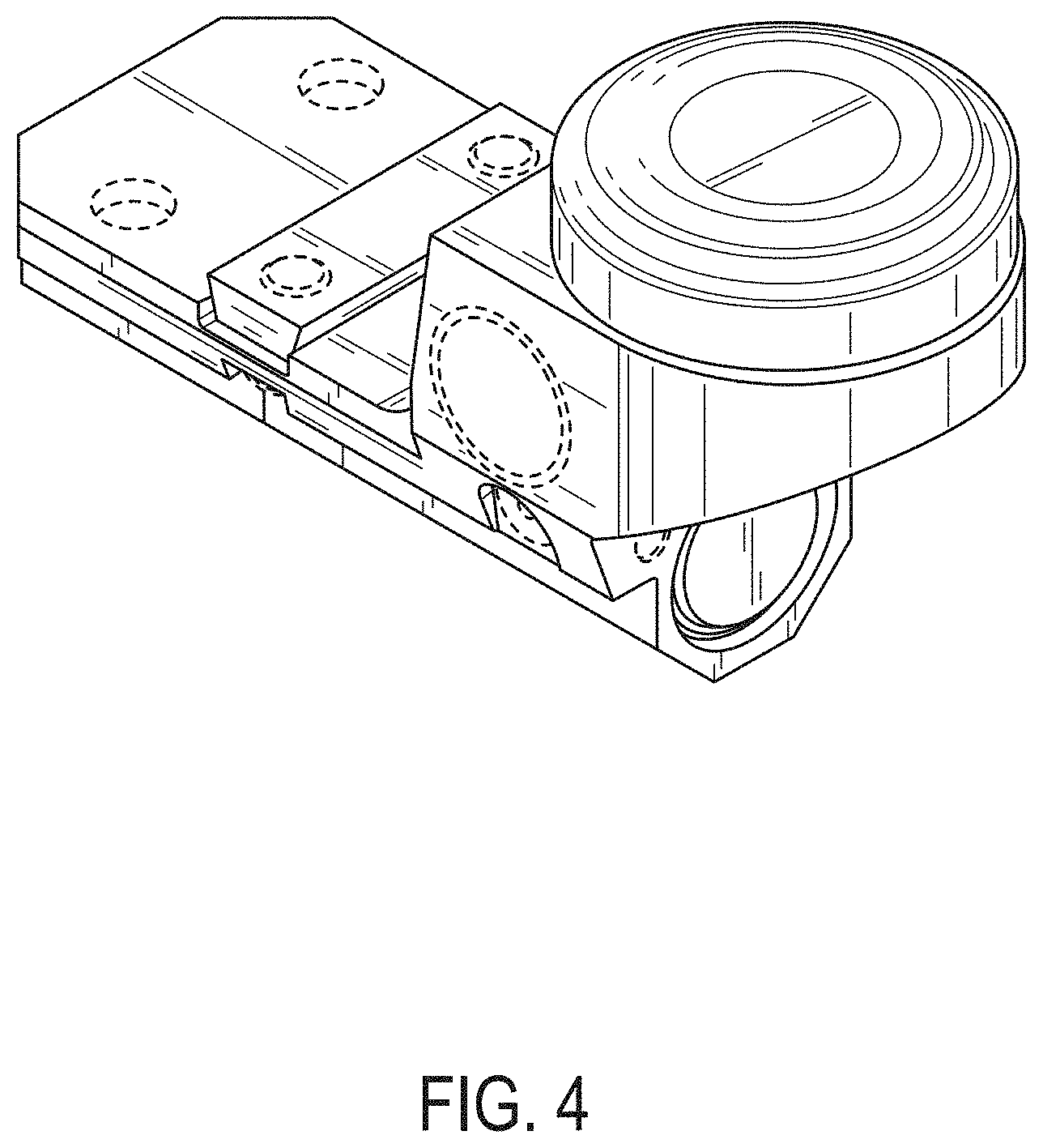
FIG. 4 is a bottom-right-rear perspective view of the optical sight.
FIG. 5 is a rear view of the optical sight.
FIG. 6 is a front view of the optical sight.
FIG. 7 is a left view of the optical sight.
FIG. 8 is a right view of the optical sight.
FIG. 9 is a top view of the optical sight.
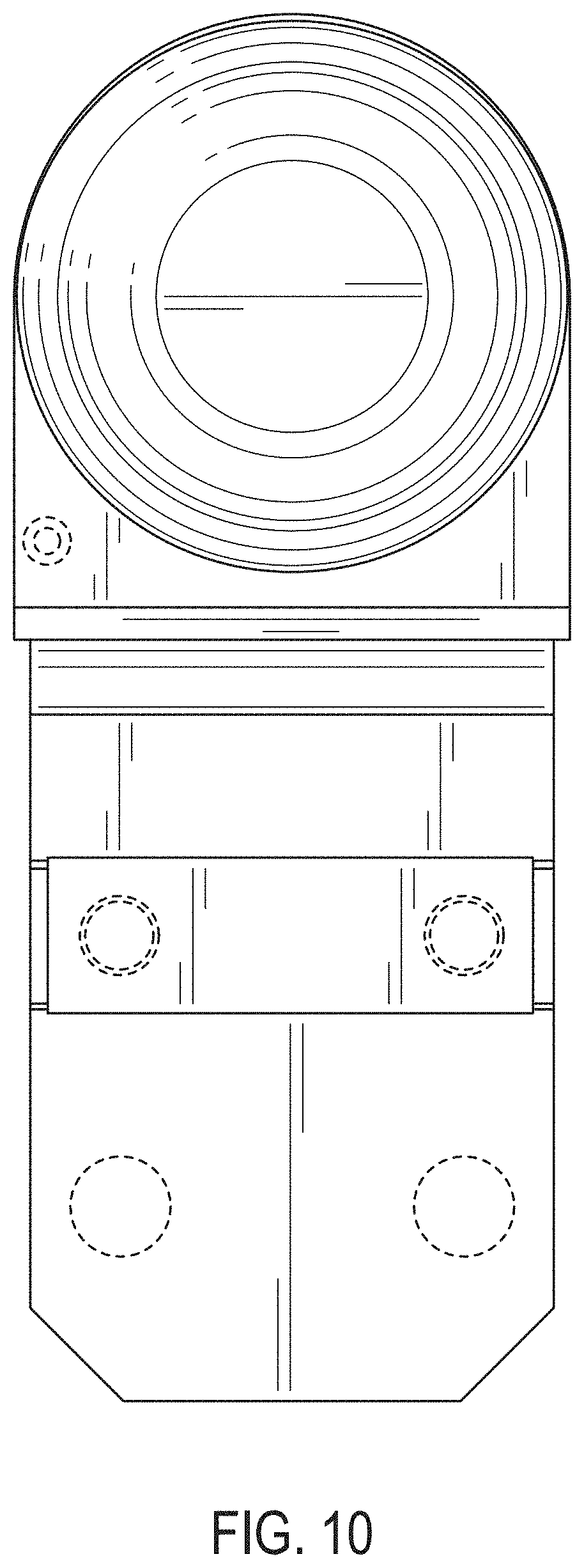
FIG. 10 is a bottom view of the optical sight; and,
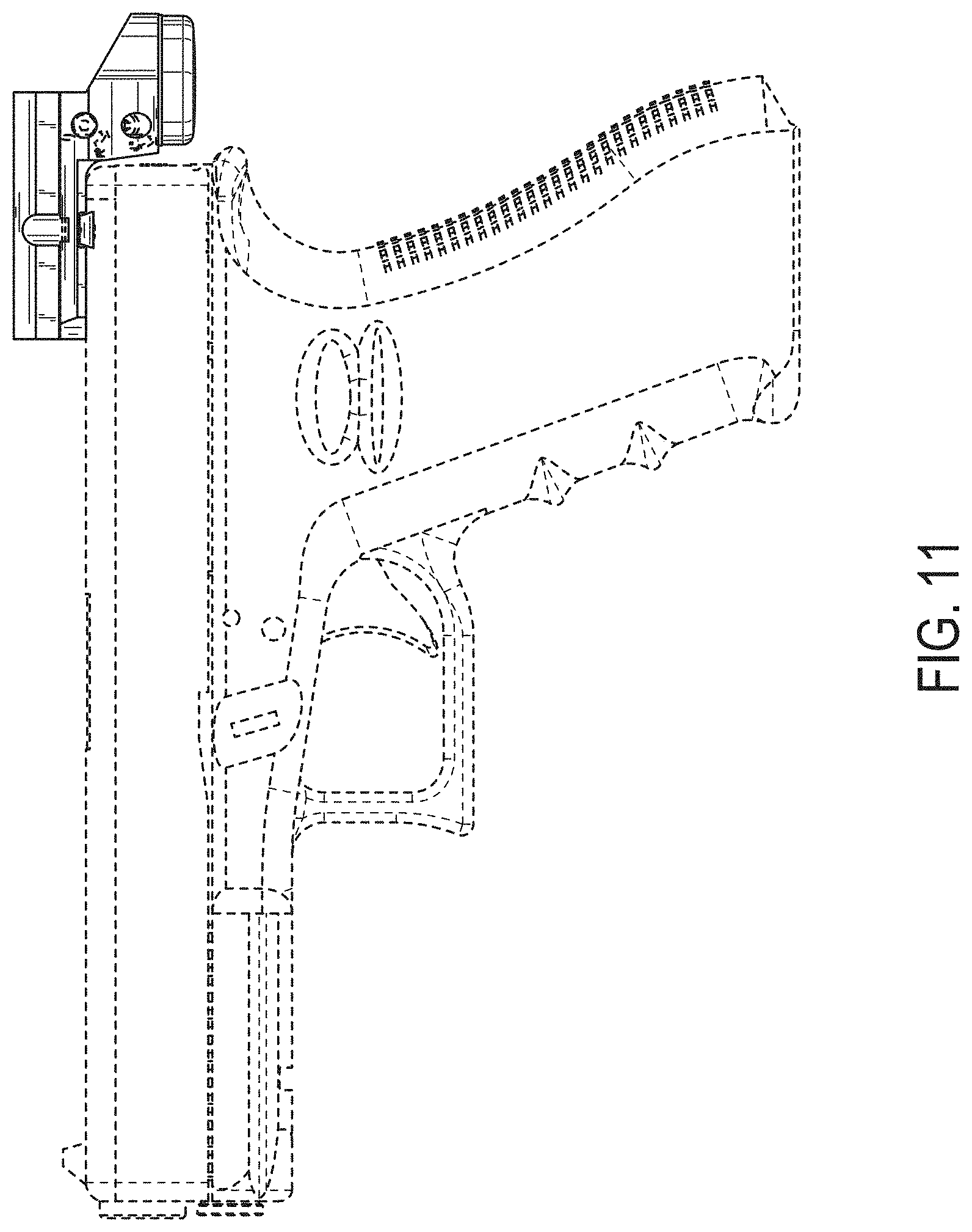
FIG. 11 is a left view of the optical sight, with the firearm shown in environment.
The broken lines in the drawings indicate portions of the optical sight and environmental subject matter that form no part of the claimed design.
* * * * *
D00000
D00001
D00002
D00003
D00004
D00005
D00006
D00007
D00008
D00009
D00010
D00011
XML
uspto.report is an independent third-party trademark research tool that is not affiliated, endorsed, or sponsored by the United States Patent and Trademark Office (USPTO) or any other governmental organization. The information provided by uspto.report is based on publicly available data at the time of writing and is intended for informational purposes only.
While we strive to provide accurate and up-to-date information, we do not guarantee the accuracy, completeness, reliability, or suitability of the information displayed on this site. The use of this site is at your own risk. Any reliance you place on such information is therefore strictly at your own risk.
All official trademark data, including owner information, should be verified by visiting the official USPTO website at www.uspto.gov. This site is not intended to replace professional legal advice and should not be used as a substitute for consulting with a legal professional who is knowledgeable about trademark law.