Exhaust stack
Parihar , et al. Sep
U.S. patent number D894,807 [Application Number D/653,323] was granted by the patent office on 2020-09-01 for exhaust stack. This patent grant is currently assigned to TRANSPORTATION IP HOLDINGS, LLC. The grantee listed for this patent is Transportation IP Holdings, LLP. Invention is credited to Ramesh Kumar, Mehmood Mohammad, Ravindra Parihar, Atmakur Raghusaraneesh, Balaji Hosadurgam Ravindranath, Andrew Theogift Jeyanth Selwyn Victor, Krishnamurthy Vaidyanathan.
| United States Patent | D894,807 |
| Parihar , et al. | September 1, 2020 |
Exhaust stack
Claims
CLAIM The ornamental design for an exhaust stack, as shown and described.
| Inventors: | Parihar; Ravindra (Bangalore, IN), Ravindranath; Balaji Hosadurgam (Bangalore, IN), Vaidyanathan; Krishnamurthy (Bangalore, IN), Kumar; Ramesh (Bangalore, IN), Mohammad; Mehmood (Bangalore, IN), Selwyn Victor; Andrew Theogift Jeyanth (Bangalore, IN), Raghusaraneesh; Atmakur (Bangalore, IN) | ||||||||||
|---|---|---|---|---|---|---|---|---|---|---|---|
| Applicant: |
|
||||||||||
| Assignee: | TRANSPORTATION IP HOLDINGS, LLC
(Norwalk, CT) |
||||||||||
| Appl. No.: | D/653,323 | ||||||||||
| Filed: | June 14, 2018 |
| Current U.S. Class: | D12/194 |
| Current International Class: | 1216 |
| Field of Search: | ;D12/194 ;D15/5 |
References Cited [Referenced By]
U.S. Patent Documents
| D694689 | December 2013 | Maholick |
| D720670 | January 2015 | Maholick |
| D745840 | December 2015 | Maholick |
| D836513 | December 2018 | Kanzal Venkatesha |
| 2005/0268595 | December 2005 | Steyer |
| 2016/0045848 | February 2016 | Campbell |
Attorney, Agent or Firm: McCoy Russell LLP
Description
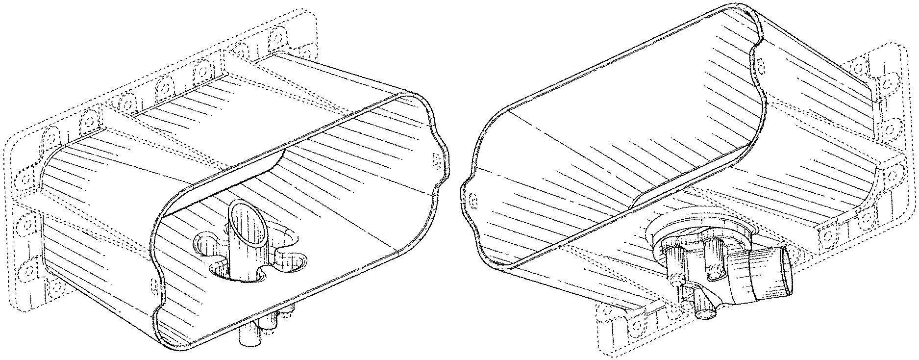
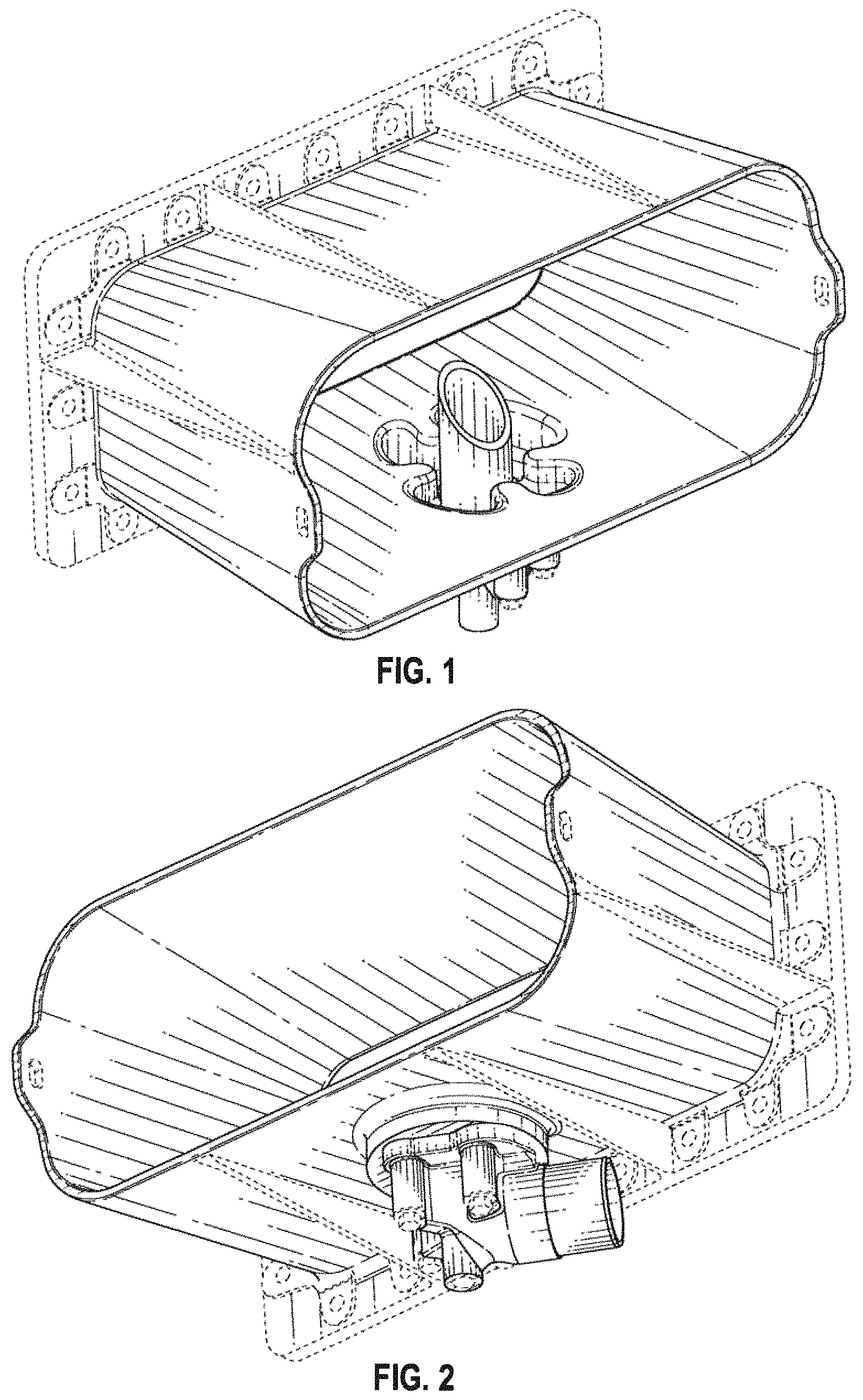
FIG. 1 is a perspective view of an exhaust stack according to a first embodiment of the invention;
FIG. 2 is a second perspective view thereof;
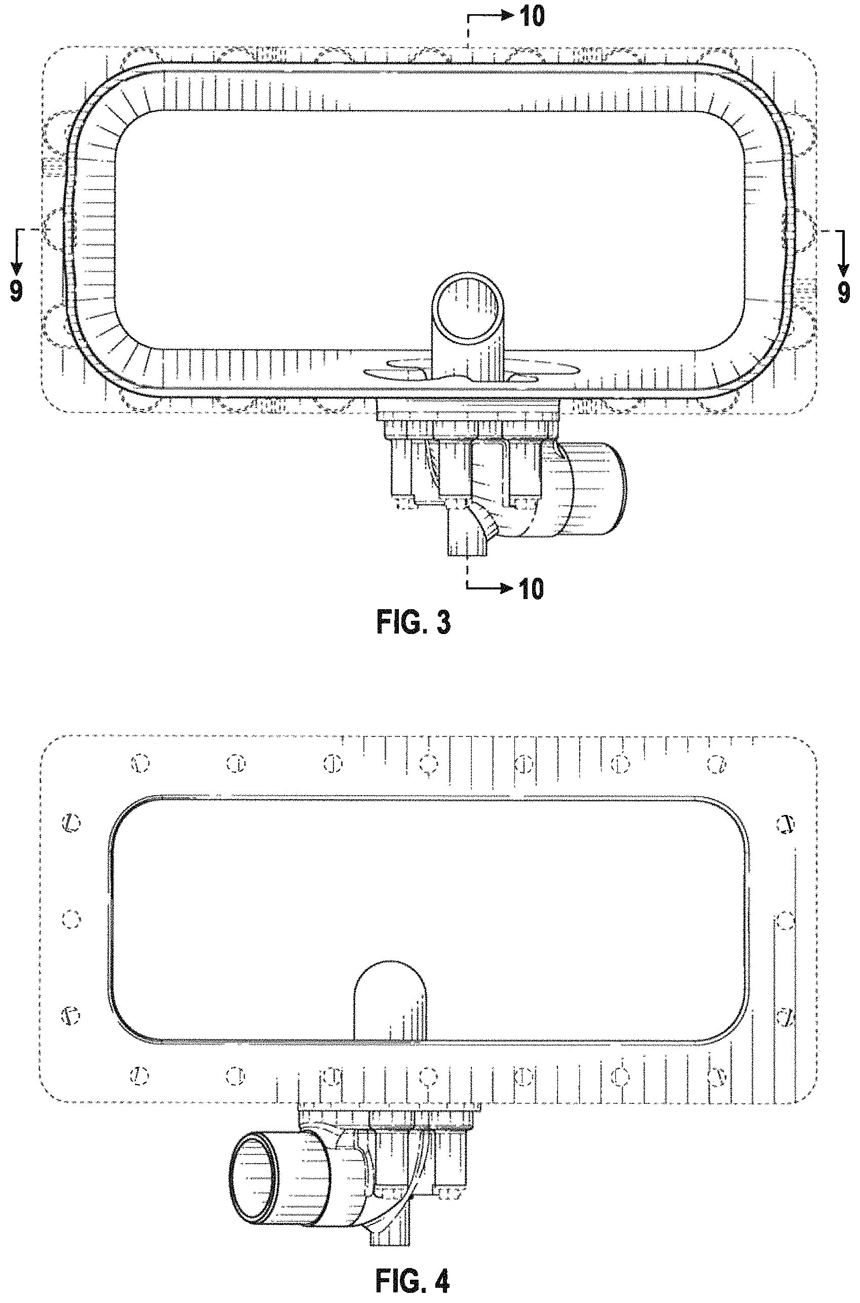
FIG. 3 is a front view thereof;
FIG. 4 is a rear view thereof;
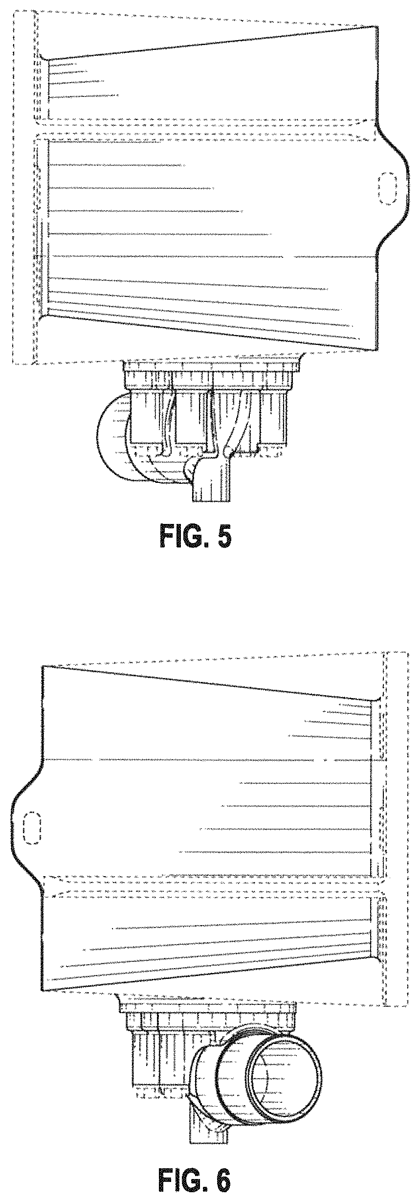
FIG. 5 is a left view thereof;
FIG. 6 is a right view thereof;
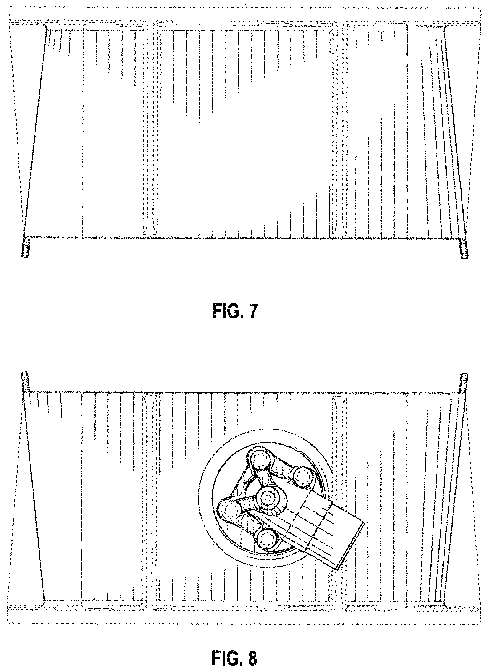
FIG. 7 is a top view thereof;
FIG. 8 is a bottom view thereof;
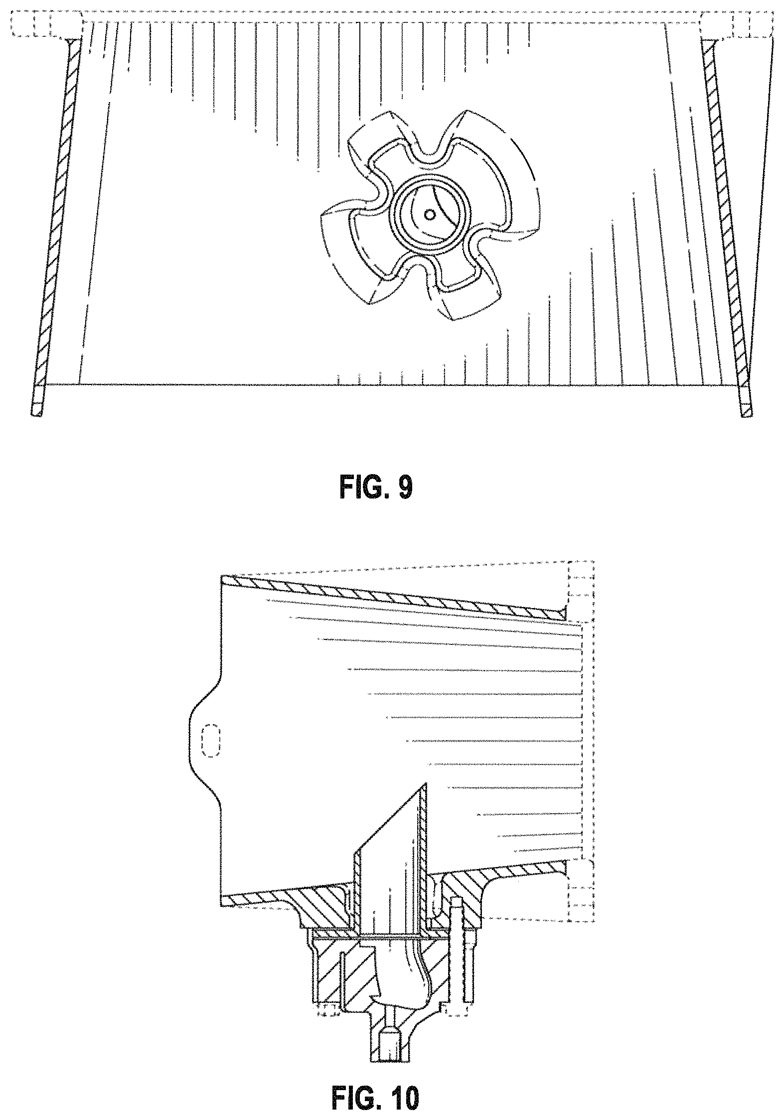
FIG. 9 is a first cross-sectional view thereof, taken along line 9-9 in FIG. 3; and,
FIG. 10 is a second cross-sectional view thereof, taken along line 10-10 in FIG. 3.
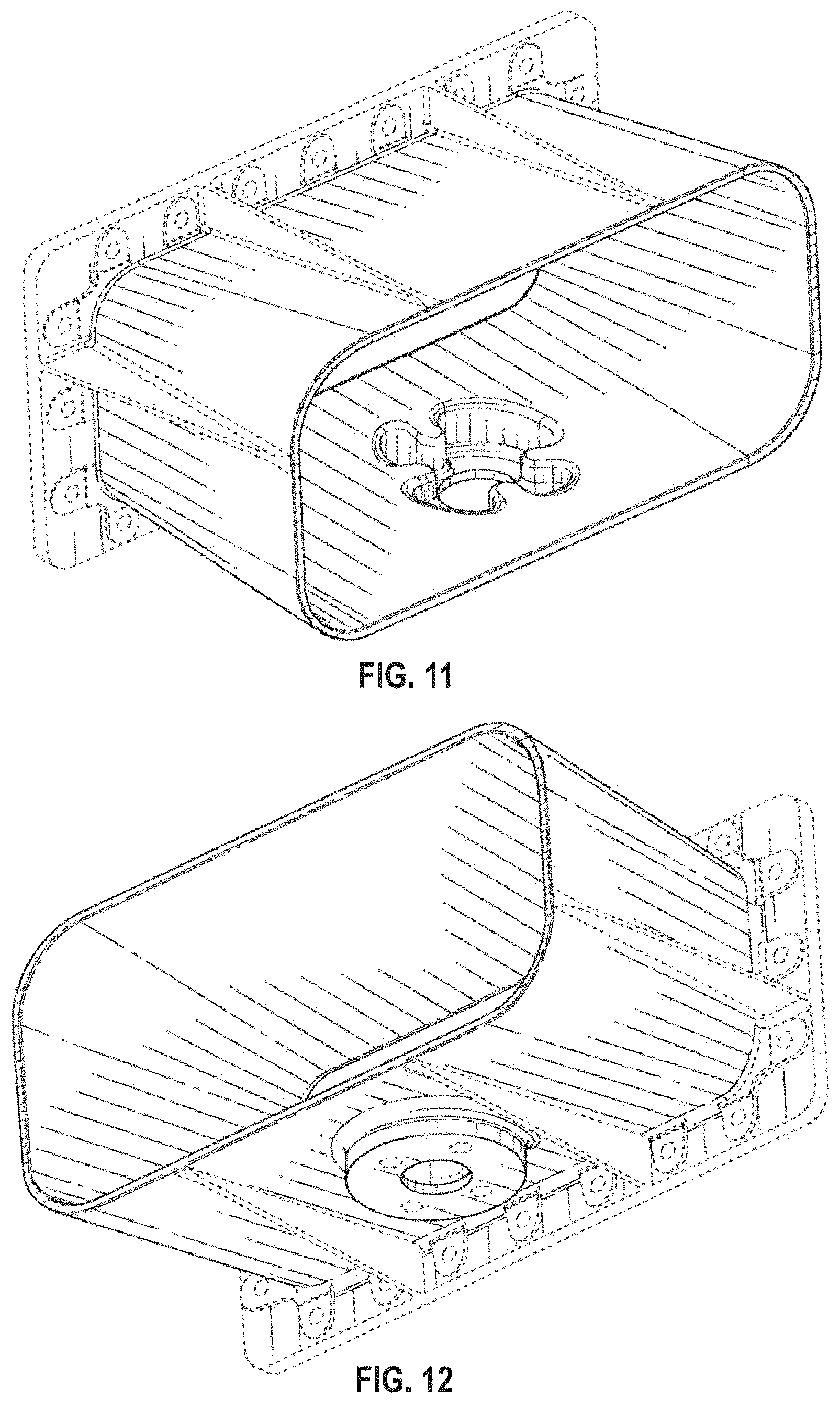
FIG. 11 is a perspective view of an exhaust stack according to a second embodiment of the invention;
FIG. 12 is a second perspective view thereof;
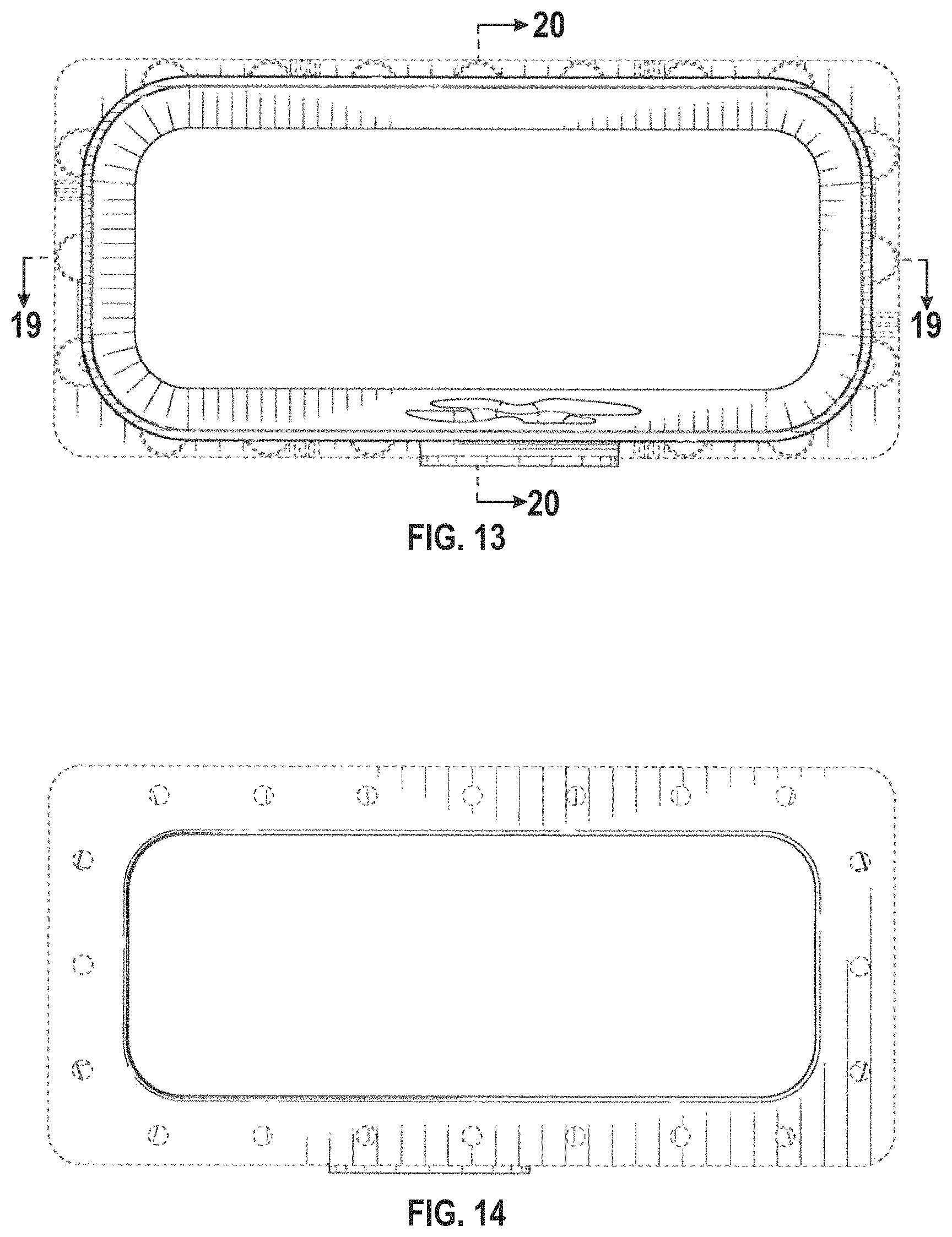
FIG. 13 is a front view thereof;
FIG. 14 is a rear view thereof;
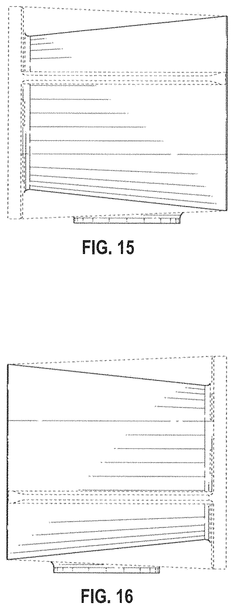
FIG. 15 is a left view thereof;
FIG. 16 is a right view thereof;
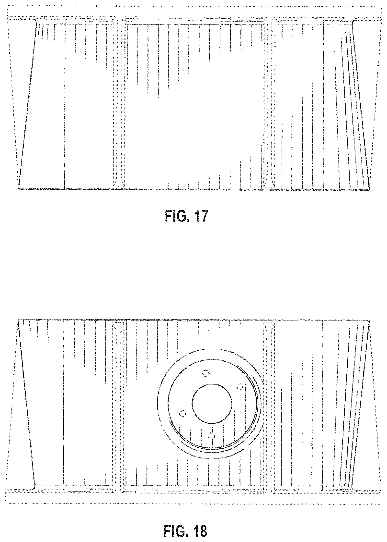
FIG. 17 is a top view thereof;
FIG. 18 is a bottom view thereof;
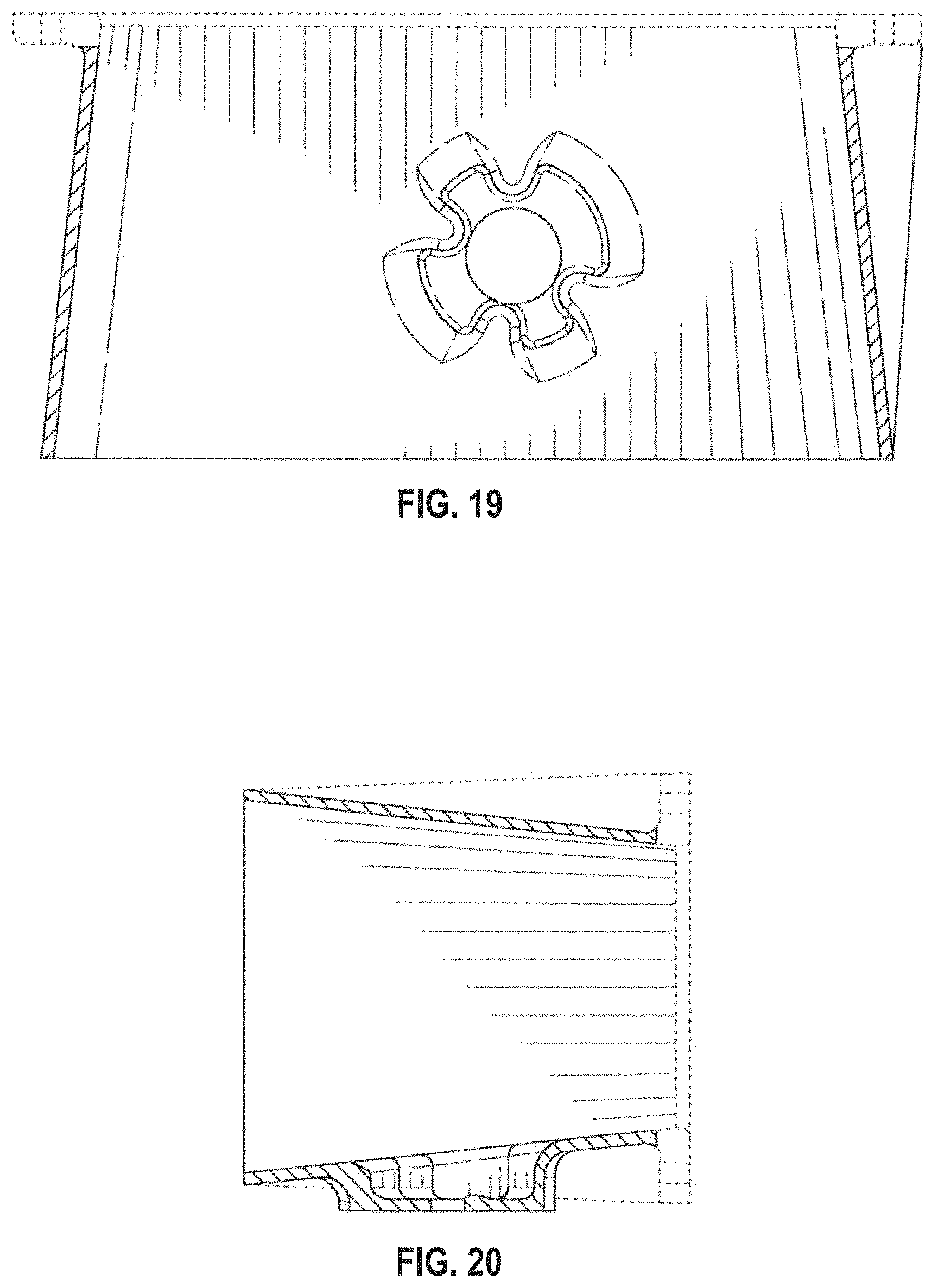
FIG. 19 is a first cross-sectional view thereof, taken along line 19-19 in FIG. 13; and,
FIG. 20 is a second cross-sectional view thereof, taken along line 20-20 in FIG. 13.
The broken line portion of the figures is included to show unclaimed subject matter only and forms no part of the claimed designs.
* * * * *
D00000
D00001
D00002
D00003
D00004
D00005
D00006
D00007
D00008
D00009
D00010
XML
uspto.report is an independent third-party trademark research tool that is not affiliated, endorsed, or sponsored by the United States Patent and Trademark Office (USPTO) or any other governmental organization. The information provided by uspto.report is based on publicly available data at the time of writing and is intended for informational purposes only.
While we strive to provide accurate and up-to-date information, we do not guarantee the accuracy, completeness, reliability, or suitability of the information displayed on this site. The use of this site is at your own risk. Any reliance you place on such information is therefore strictly at your own risk.
All official trademark data, including owner information, should be verified by visiting the official USPTO website at www.uspto.gov. This site is not intended to replace professional legal advice and should not be used as a substitute for consulting with a legal professional who is knowledgeable about trademark law.