Cut-on-contact broadhead
Blosser , et al. A
U.S. patent number D894,312 [Application Number D/666,819] was granted by the patent office on 2020-08-25 for cut-on-contact broadhead. This patent grant is currently assigned to FeraDyne Outdoors, LLC. The grantee listed for this patent is FeraDyne Outdoors, LLC. Invention is credited to Benjamin D. Blosser, Jon Arthur Syverson.


View All Diagrams
| United States Patent | D894,312 |
| Blosser , et al. | August 25, 2020 |
Cut-on-contact broadhead
Claims
CLAIM The ornamental design for a cut-on-contact broadhead, as shown and described.
| Inventors: | Blosser; Benjamin D. (Corydon, KY), Syverson; Jon Arthur (Cloquet, MN) | ||||||||||
|---|---|---|---|---|---|---|---|---|---|---|---|
| Applicant: |
|
||||||||||
| Assignee: | FeraDyne Outdoors, LLC
(Superior, WI) |
||||||||||
| Family ID: | 66095686 | ||||||||||
| Appl. No.: | D/666,819 | ||||||||||
| Filed: | October 16, 2018 |
Related U.S. Patent Documents
| Application Number | Filing Date | Patent Number | Issue Date | ||
|---|---|---|---|---|---|
| 16161713 | Oct 16, 2018 | 10458763 | |||
| Current U.S. Class: | D22/107 |
| Current CPC Class: | F42B6/08 20130101 |
| Current International Class: | 2201 |
| Field of Search: | ;D22/107 |
References Cited [Referenced By]
U.S. Patent Documents
| D730471 | May 2015 | Pedersen |
| D743500 | November 2015 | Pedersen |
| D776782 | January 2017 | Pedersen |
| D847290 | April 2019 | Betty |
| D870231 | December 2019 | Haas |
| 2015/0354928 | December 2015 | Mizek |
| 2017/0122712 | May 2017 | Hahn |
| 2019/0219372 | July 2019 | Haas |
| 2019/0390945 | December 2019 | Blosser |
Attorney, Agent or Firm: Greenberg Traurig, LLP Shah; Dipak J.
Description
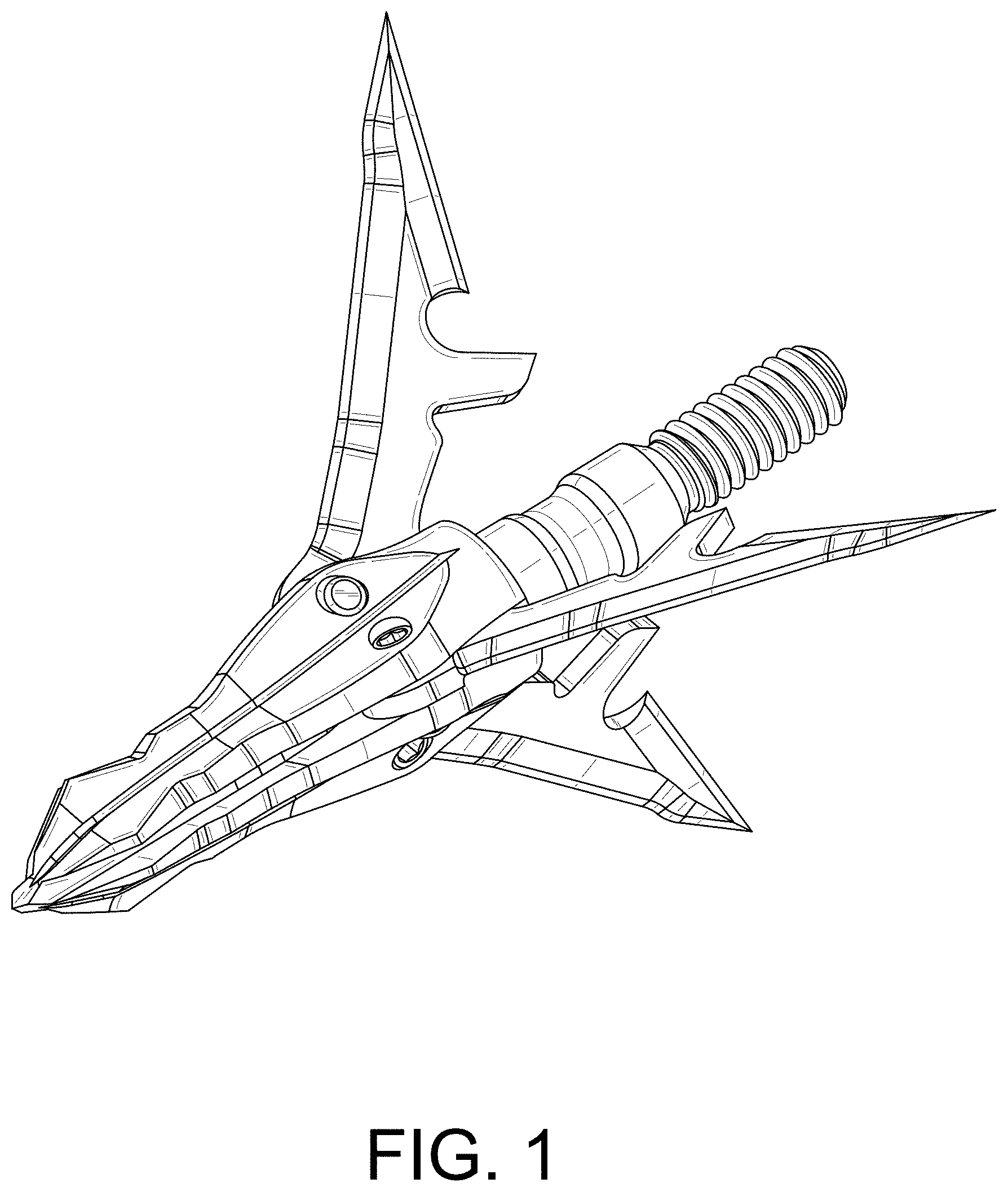
FIG. 1 is a perspective view of a cut-on-contact broadhead of the instant disclosure illustrated with the blades fully deployed;
FIG. 2 is another perspective view of the broadhead of FIG. 1;
FIG. 3 is another perspective view of the broadhead of FIG. 1;
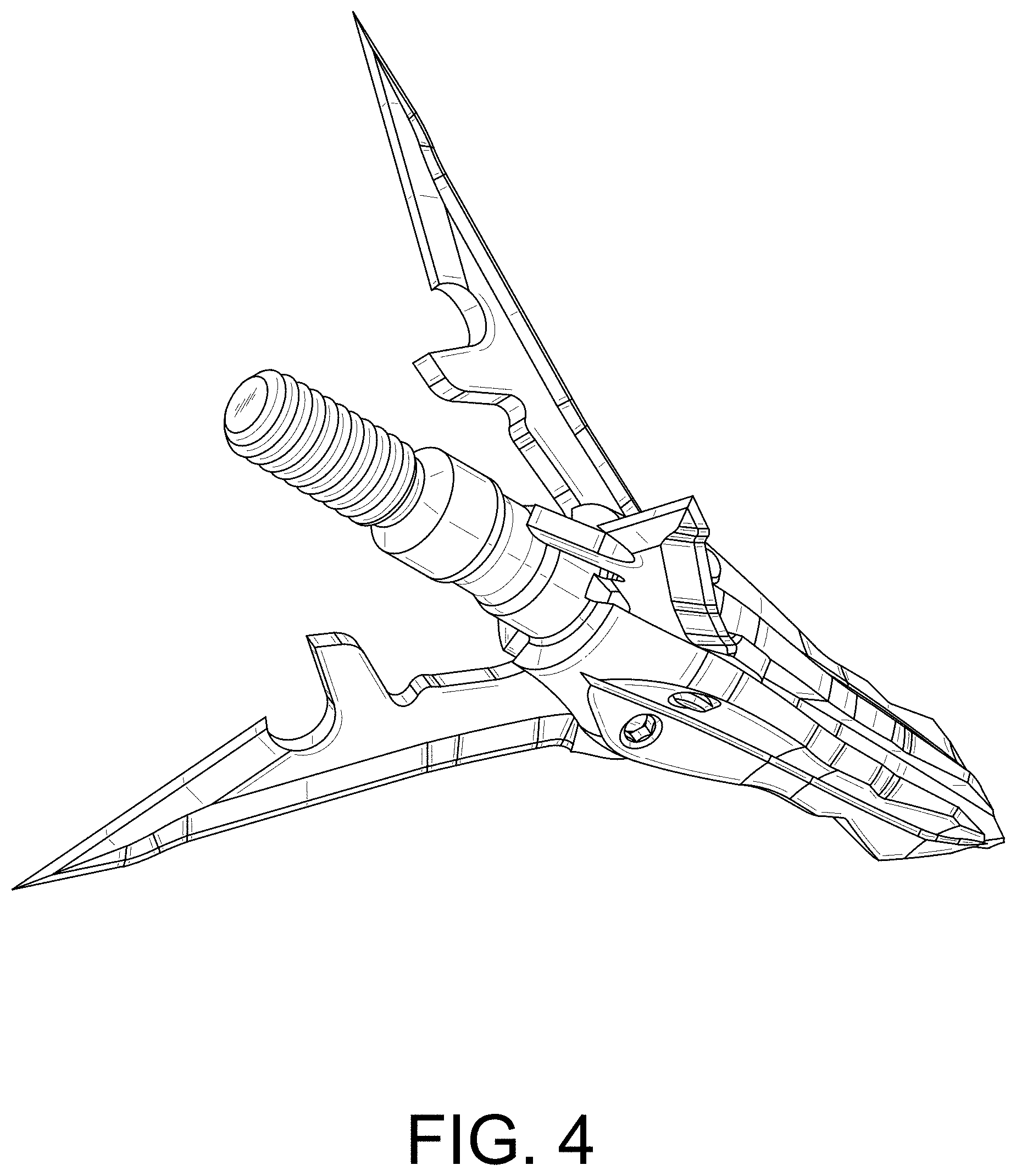
FIG. 4 is another perspective view of the broadhead of FIG. 1;
FIG. 5 is an elevation view of the broadhead of FIG. 1 as viewed from a proximal (rear) location;
FIG. 6 is an elevation view of the broadhead of FIG. 1 as viewed from a distal (front) location;
FIG. 7 is a plan view of the broadhead of FIG. 1;
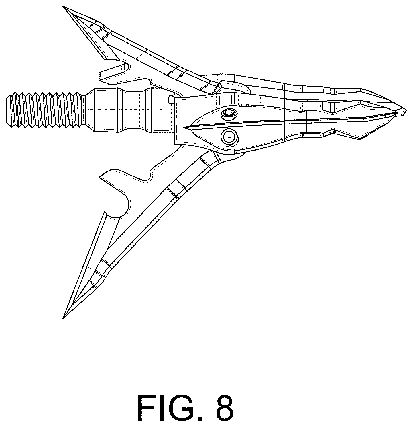
FIG. 8 is another plan view of the broadhead of FIG. 1;
FIG. 9 is another plan view of the broadhead of FIG. 1;
FIG. 10 is another plan view of the broadhead of FIG. 1;
FIG. 11 is a perspective view of the broadhead of FIG. 1 illustrated with the blades fully retracted;
FIG. 12 is another perspective view of the broadhead of FIG. 11;
FIG. 13 is another perspective view of the broadhead of FIG. 11;
FIG. 14 is another perspective view of the broadhead of FIG. 11;
FIG. 15 is an elevation view of the broadhead of FIG. 11 as viewed from the proximal (rear) location;
FIG. 16 is an elevation view of the broadhead of FIG. 11 as viewed from the distal (front) location;
FIG. 17 is a plan view of the broadhead of FIG. 11;
FIG. 18 is another plan view of the broadhead of FIG. 11;
FIG. 19 is another plan view of the broadhead of FIG. 11; and,
FIG. 20 is another plan view of the broadhead of FIG. 11.
Where included, broken lines showing structural and/or other features in the various embodiments of the cut-on-contact broadhead are for illustrative purposes only and, as such, form no part of the claimed design.
* * * * *
D00000
D00001
D00002
D00003
D00004
D00005
D00006
D00007
D00008
D00009
D00010
D00011
D00012

D00013

D00014

D00015

D00016

D00017

XML
uspto.report is an independent third-party trademark research tool that is not affiliated, endorsed, or sponsored by the United States Patent and Trademark Office (USPTO) or any other governmental organization. The information provided by uspto.report is based on publicly available data at the time of writing and is intended for informational purposes only.
While we strive to provide accurate and up-to-date information, we do not guarantee the accuracy, completeness, reliability, or suitability of the information displayed on this site. The use of this site is at your own risk. Any reliance you place on such information is therefore strictly at your own risk.
All official trademark data, including owner information, should be verified by visiting the official USPTO website at www.uspto.gov. This site is not intended to replace professional legal advice and should not be used as a substitute for consulting with a legal professional who is knowledgeable about trademark law.