Wrench socket holder
Albertson A
U.S. patent number D892,587 [Application Number D/651,537] was granted by the patent office on 2020-08-11 for wrench socket holder. This patent grant is currently assigned to ALBERTSON ENTERPRISES, LLC. The grantee listed for this patent is Robert V. Albertson. Invention is credited to Robert V. Albertson.


| United States Patent | D892,587 |
| Albertson | August 11, 2020 |
Wrench socket holder
Claims
CLAIM The ornamental design of a wrench socket holder, as shown and described.
| Inventors: | Albertson; Robert V. (Mound, MN) | ||||||||||
|---|---|---|---|---|---|---|---|---|---|---|---|
| Applicant: |
|
||||||||||
| Assignee: | ALBERTSON ENTERPRISES, LLC
(Mound, MN) |
||||||||||
| Appl. No.: | D/651,537 | ||||||||||
| Filed: | August 23, 2018 |
| Current U.S. Class: | D8/71; D8/25 |
| Current International Class: | 0805 |
| Field of Search: | ;D8/21-29,29.1,114,499,321,81,52,61,107,57,346,334,333,72-75,393-395,63,93,14,330,336,400,349,467,356,692,693,17,367,368,369,370,371 ;81/119,177.1,177.2,57.5,478,177.7,177.8,166 ;16/87.4R,87.2 ;D15/148,140,138,5 ;D21/692-694 |
References Cited [Referenced By]
U.S. Patent Documents
| 2219457 | October 1940 | Schweitzer, Jr. |
| 2834241 | May 1958 | Chowning |
| 3727771 | April 1973 | Hoffman |
| 4591817 | May 1986 | Miller |
| 4826021 | May 1989 | Burrel |
| D342432 | December 1993 | Sadoway |
| D356526 | March 1995 | Burns |
| D366114 | January 1996 | Ohata |
| 5500631 | March 1996 | Negus |
| 5603248 | February 1997 | Eggert et al. |
| 5743395 | April 1998 | Backer |
| 5996757 | December 1999 | Hofmann |
| 6092655 | July 2000 | Ernst |
| 6092656 | July 2000 | Ernst |
| 6508002 | January 2003 | Chiang |
| D480938 | October 2003 | Whitley |
| D528882 | September 2006 | Dobras |
| D665639 | August 2012 | Albertson |
| 2002/0057978 | May 2002 | Johansen |
| 2007/0213155 | September 2007 | Reiter |
| 2012/0135830 | May 2012 | Burke |
| 2013/0049520 | February 2013 | Hwang |
| 2015/0123510 | May 2015 | Dajaku |
| 2016/0258523 | September 2016 | Reineke |
| 2017/0016524 | January 2017 | Cheng |
| 2015-719980 | May 2015 | CN | |||
Assistant Examiner: Sahneh; Sara S
Attorney, Agent or Firm: Bartz; Richard John
Description
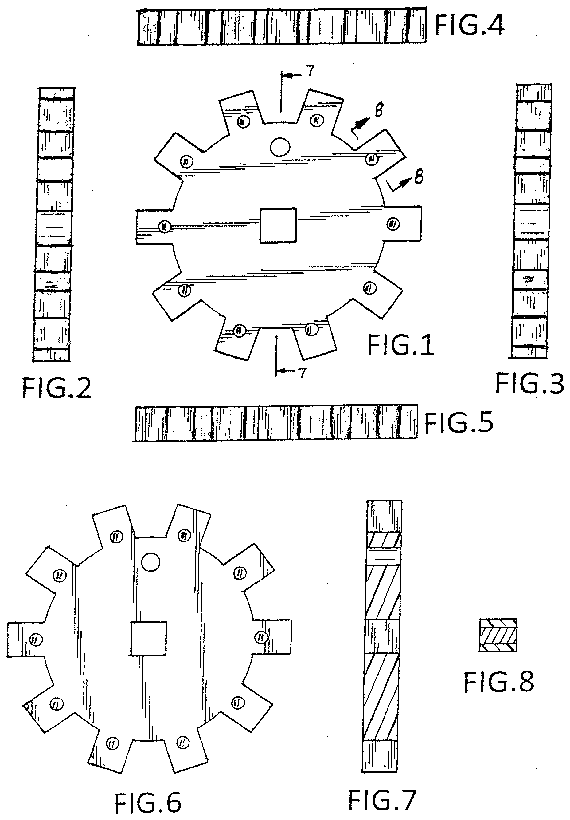
FIG. 1 is a front elevational view of a first embodiment of the wrench socket holder of my design;
FIG. 2 is a left side elevational view thereof;
FIG. 3 is a right side elevational view thereof;
FIG. 4 is a top plan view thereof;
FIG. 5 is a bottom plan view thereof;
FIG. 6 is back elevational view thereof;
FIG. 7 is a sectional view taken along line 7-7 of FIG. 1;
FIG. 8 is a sectional view taken along line 8-8 of FIG. 1;
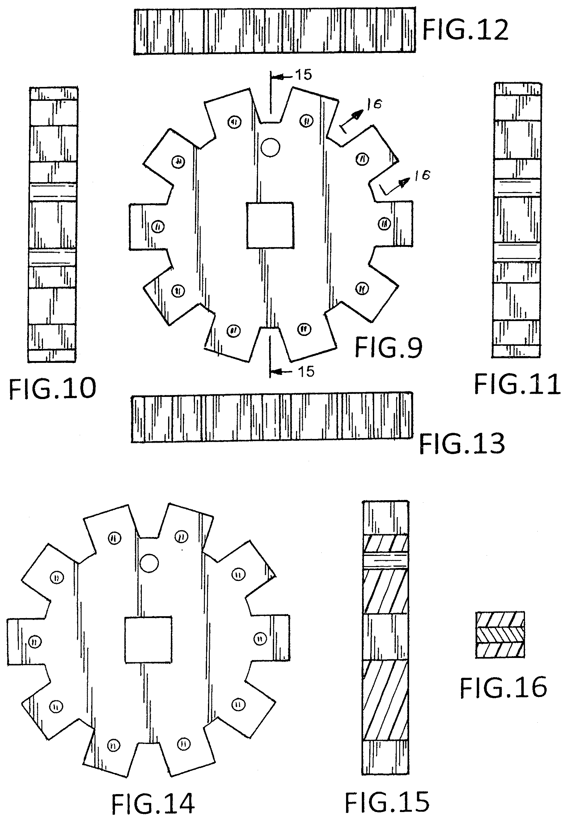
FIG. 9 is a front elevational view of a second embodiment of the wrench socket holder of my design;
FIG. 10 is a left side elevational view of FIG. 9;
FIG. 11 is a right side elevational view of FIG. 9;
FIG. 12 is a top plan view of FIG. 9;
FIG. 13 is a bottom plan view of FIG. 9;
FIG. 14 is back elevational view of FIG. 9;
FIG. 15 is a sectional view taken along line 15-15 of FIG. 9;
FIG. 16 is a sectional view taken along line 16-16 of FIG. 9;
FIG. 17 is a front elevational view of a third embodiment of the wrench socket holder of my design;
FIG. 18 is a left side elevational view of FIG. 17;
FIG. 19 is a right side elevational view of FIG. 17;
FIG. 20 is a top plan view of FIG. 17;
FIG. 21 is a bottom plan view of FIG. 17;
FIG. 22 is back elevational view of FIG. 17;
FIG. 23 is a sectional view taken along line 23-23 of FIG. 17;
FIG. 24 is a sectional view taken along line 24-24 of FIG. 17;
FIG. 25 is a front elevational view of a fourth embodiment of the wrench socket holder of my design;
FIG. 26 is a left side elevational view of FIG. 25;
FIG. 27 is a right side elevational view of FIG. 25;
FIG. 28 is a top plan view of FIG. 25;
FIG. 29 is a bottom plan view of FIG. 25;
FIG. 30 is back elevational view of FIG. 25;
FIG. 31 is a sectional view taken along line 31-31 of FIG. 25; and,
FIG. 32 is a sectional view taken along line 32-32 of FIG. 25.
* * * * *
D00000
D00001
D00002
D00003
D00004
XML
uspto.report is an independent third-party trademark research tool that is not affiliated, endorsed, or sponsored by the United States Patent and Trademark Office (USPTO) or any other governmental organization. The information provided by uspto.report is based on publicly available data at the time of writing and is intended for informational purposes only.
While we strive to provide accurate and up-to-date information, we do not guarantee the accuracy, completeness, reliability, or suitability of the information displayed on this site. The use of this site is at your own risk. Any reliance you place on such information is therefore strictly at your own risk.
All official trademark data, including owner information, should be verified by visiting the official USPTO website at www.uspto.gov. This site is not intended to replace professional legal advice and should not be used as a substitute for consulting with a legal professional who is knowledgeable about trademark law.