Osteosynthesis clip features
Hollis , et al.
U.S. patent number D892,331 [Application Number D/711,467] was granted by the patent office on 2020-08-04 for osteosynthesis clip features. This patent grant is currently assigned to CROSSROADS EXTREMITY SYSTEMS, LLC. The grantee listed for this patent is CROSSROADS EXTREMITY SYSTEMS, LLC. Invention is credited to Vernon R. Hartdegen, Michael Chad Hollis.


View All Diagrams
| United States Patent | D892,331 |
| Hollis , et al. | August 4, 2020 |
Osteosynthesis clip features
Claims
CLAIM The ornamental design for osteosynthesis clip features, as shown and described.
| Inventors: | Hollis; Michael Chad (Collierville, TN), Hartdegen; Vernon R. (Collierville, TN) | ||||||||||
|---|---|---|---|---|---|---|---|---|---|---|---|
| Applicant: |
|
||||||||||
| Assignee: | CROSSROADS EXTREMITY SYSTEMS,
LLC (Memphis, TN) |
||||||||||
| Appl. No.: | D/711,467 | ||||||||||
| Filed: | October 31, 2019 |
Related U.S. Patent Documents
| Application Number | Filing Date | Patent Number | Issue Date | ||
|---|---|---|---|---|---|
| 29612208 | Jul 31, 2017 | D870284 | |||
| Current U.S. Class: | D24/155 |
| Current International Class: | 2403 |
| Field of Search: | ;D24/155-157 ;D8/390 |
References Cited [Referenced By]
U.S. Patent Documents
| 2133859 | October 1938 | Hawley |
| 2811073 | October 1957 | Klopstock |
| 3636954 | January 1972 | Weston |
| 3939828 | February 1976 | Mohr |
| 4014244 | March 1977 | Larson |
| 4434796 | March 1984 | Karapetian |
| D281814 | December 1985 | Pratt |
| 4719917 | January 1988 | Barrows |
| 5015135 | May 1991 | Chamings |
| 5425489 | June 1995 | Shichman |
| 5785713 | July 1998 | Jobe |
| 6626916 | September 2003 | Yeung |
| D484032 | December 2003 | Del Re |
| 7240677 | July 2007 | Fox |
| 7398907 | July 2008 | Racenet |
| D586915 | February 2009 | Grim |
| D625417 | October 2010 | Fox |
| 8137351 | March 2012 | Prandi |
| 8337537 | December 2012 | Pelo |
| 8540778 | September 2013 | Rhodes |
| 8657820 | February 2014 | Kubiak |
| D707357 | June 2014 | Cheney |
| 8870882 | October 2014 | Kleiner |
| 8951254 | February 2015 | Mayer |
| 9017331 | April 2015 | Fox |
| 9095338 | August 2015 | Taylor |
| 9101349 | August 2015 | Knight |
| 9107661 | August 2015 | Euteneuer |
| 9180022 | November 2015 | Georges |
| 9271726 | March 2016 | Euteneuer |
| 9295463 | March 2016 | Viola |
| 9402624 | August 2016 | Scott |
| D780311 | February 2017 | Cheney |
| 9615856 | April 2017 | Arnett |
| 9855036 | January 2018 | Palmer |
| 9901338 | February 2018 | Anderson |
| 9955964 | May 2018 | Mayer |
| 10016198 | July 2018 | Morgan |
| 10166022 | January 2019 | Early |
| D865178 | October 2019 | Sammarco |
| 10456130 | October 2019 | Cheney |
| D870284 | December 2019 | Hollis |
| 10492841 | December 2019 | Hartdegen |
| 2002/0019636 | February 2002 | Ogilvie |
| 2003/0158553 | August 2003 | Michelson |
| 2005/0021035 | January 2005 | Groiso |
| 2006/0058802 | March 2006 | Kofoed |
| 2008/0015598 | January 2008 | Prommersberger |
| 2009/0254090 | October 2009 | Lizee |
| 2010/0069928 | March 2010 | Bauer |
| 2010/0082065 | April 2010 | Butler |
| 2010/0133316 | June 2010 | Lizee |
| 2011/0022099 | January 2011 | Ashman |
| 2011/0118796 | May 2011 | Reiley |
| 2011/0118840 | May 2011 | Huntsman |
| 2012/0228355 | September 2012 | Combrowski |
| 2013/0068815 | March 2013 | Bruewer |
| 2013/0231667 | September 2013 | Taylor |
| 2013/0267956 | October 2013 | Terrill |
| 2013/0345752 | December 2013 | Hendren |
| 2014/0018809 | January 2014 | Allen |
| 2015/0313592 | November 2015 | Coillard-Lavirotte |
| 2015/0359534 | December 2015 | Gibbons, Jr. |
| 2016/0100835 | April 2016 | Linder |
| 2016/0354117 | December 2016 | Nakaji |
| 2017/0000533 | January 2017 | Fallin |
| 2017/0007305 | January 2017 | Hollis |
| 2017/0202552 | July 2017 | Coleman |
| 2017/0354509 | December 2017 | Finley |
| 2019/0046183 | February 2019 | Hartdegen |
| 2019/0133777 | May 2019 | Muller |
| 20001879 | May 2000 | DE | |||
| 10116168 | Nov 2001 | DE | |||
| 826340 | Mar 1998 | EP | |||
| WO1992017122 | Oct 1992 | WO | |||
| WO2008129061 | Oct 2008 | WO | |||
| WO2010004602 | Jan 2010 | WO | |||
| WO2012088575 | Jul 2012 | WO | |||
| WO2013186205 | Dec 2013 | WO | |||
Attorney, Agent or Firm: Maywood IP Law Hays; G. Jo Meibos; David W.
Description
FIG. 1 is a top perspective view of osteosynthesis clip features;
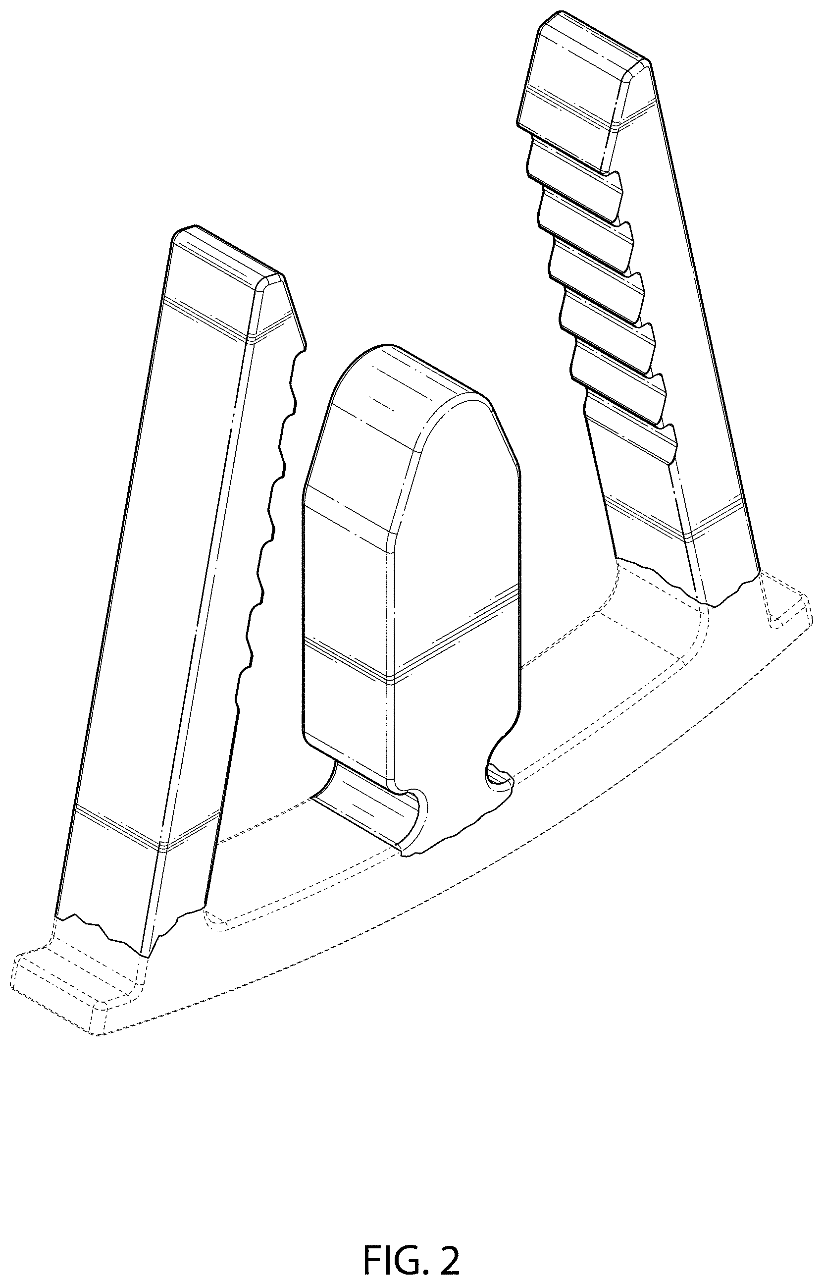
FIG. 2 is a bottom perspective view of the osteosynthesis clip features of FIG. 1;
FIG. 3 is a front view of the osteosynthesis clip features of FIG. 1;
FIG. 4 is a back view of the osteosynthesis clip features of FIG. 1;
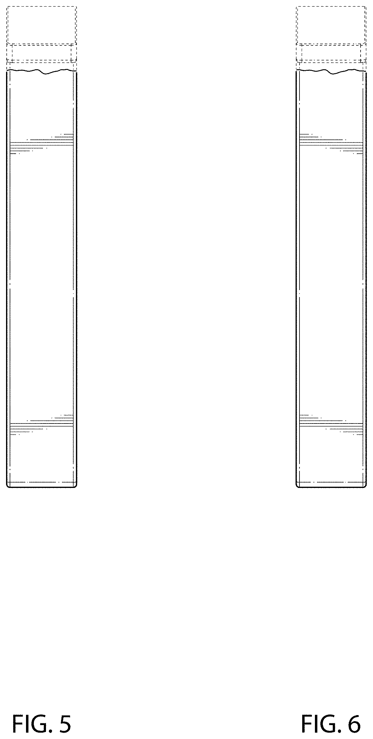
FIG. 5 is a left view of the osteosynthesis clip features of FIG. 1;
FIG. 6 is a right view of the osteosynthesis clip features of FIG. 1;
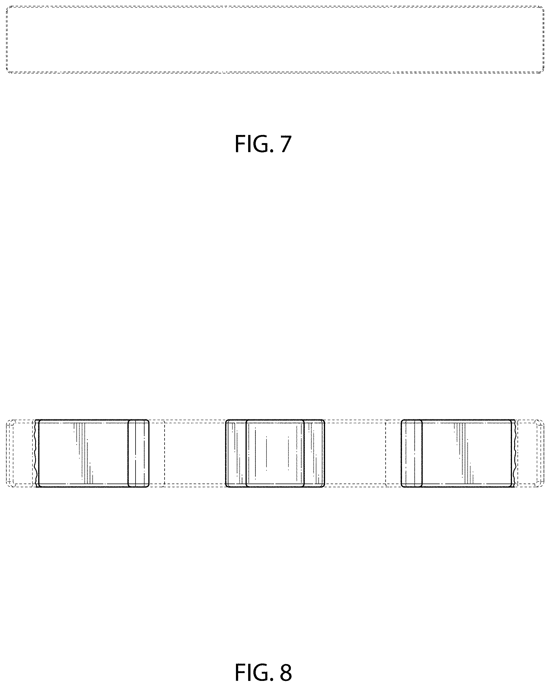
FIG. 7 is a top view of the osteosynthesis clip features of FIG. 1;
FIG. 8 is a bottom view of the osteosynthesis features clip of FIG. 1;
FIG. 9 is a top perspective view of another set of osteosynthesis clip features;
FIG. 10 is a bottom perspective view of the osteosynthesis clip features of FIG. 9;
FIG. 11 is a front view of the osteosynthesis clip features of FIG. 9;
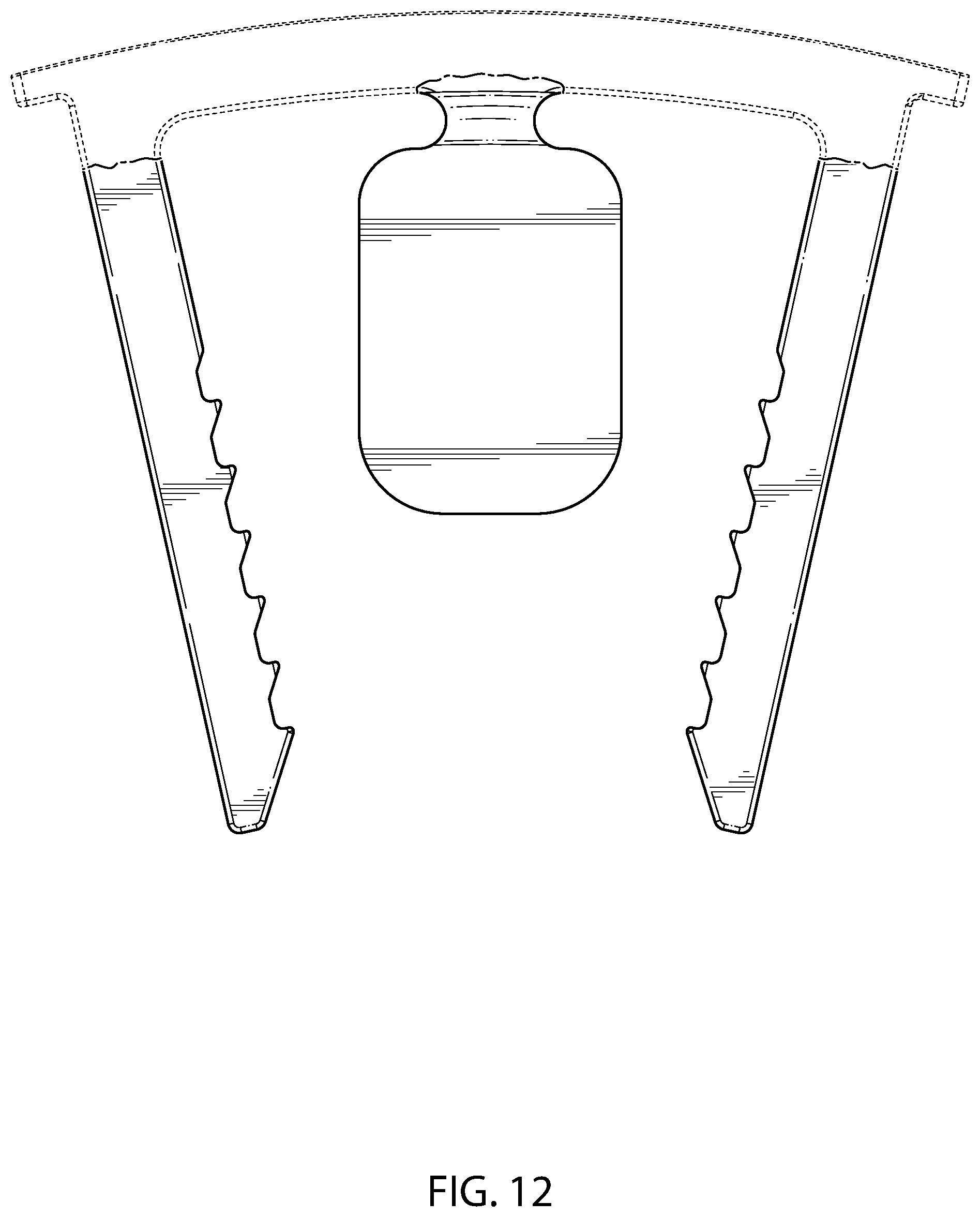
FIG. 12 is a back view of the osteosynthesis clip features of FIG. 9;
FIG. 13 is a left view of the osteosynthesis clip features of FIG. 9;
FIG. 14 is a right view of the osteosynthesis clip features of FIG. 9;
FIG. 15 is a top view of the osteosynthesis clip features of FIG. 9; and,
FIG. 16 is a bottom view of the osteosynthesis clip features of FIG. 9.
In the drawings, the broken lines depict environmental subject matter only and form no part of the claimed design.
* * * * *
D00000
D00001
D00002
D00003
D00004
D00005
D00006
D00007
D00008
D00009
D00010
D00011
D00012

XML
uspto.report is an independent third-party trademark research tool that is not affiliated, endorsed, or sponsored by the United States Patent and Trademark Office (USPTO) or any other governmental organization. The information provided by uspto.report is based on publicly available data at the time of writing and is intended for informational purposes only.
While we strive to provide accurate and up-to-date information, we do not guarantee the accuracy, completeness, reliability, or suitability of the information displayed on this site. The use of this site is at your own risk. Any reliance you place on such information is therefore strictly at your own risk.
All official trademark data, including owner information, should be verified by visiting the official USPTO website at www.uspto.gov. This site is not intended to replace professional legal advice and should not be used as a substitute for consulting with a legal professional who is knowledgeable about trademark law.