Ball projectile
Enderle , et al.
U.S. patent number D892,241 [Application Number D/662,242] was granted by the patent office on 2020-08-04 for ball projectile. This patent grant is currently assigned to HASBRO, INC.. The grantee listed for this patent is Hasbro, Inc.. Invention is credited to Alyssa Enderle, Jae Hoon Yoo.


View All Diagrams
| United States Patent | D892,241 |
| Enderle , et al. | August 4, 2020 |
Ball projectile
Claims
CLAIM The ornamental design for a ball projectile, as shown and described.
| Inventors: | Enderle; Alyssa (Providence, RI), Yoo; Jae Hoon (North Attleboro, MA) | ||||||||||
|---|---|---|---|---|---|---|---|---|---|---|---|
| Applicant: |
|
||||||||||
| Assignee: | HASBRO, INC. (Pawtucket,
RI) |
||||||||||
| Appl. No.: | D/662,242 | ||||||||||
| Filed: | September 4, 2018 |
| Current U.S. Class: | D21/709 |
| Current International Class: | 2102 |
| Field of Search: | ;D21/707-714 ;473/165,280,281,351-385,569-577,588,593-615 ;40/327 ;D11/44,48,81,121,125,131,149,157 |
References Cited [Referenced By]
U.S. Patent Documents
| D44175 | June 1913 | Martin et al. |
| D44176 | June 1913 | Martin et al. |
| D44177 | June 1913 | Martin et al. |
| 1572527 | February 1926 | Goldsworthy |
| 1583721 | May 1926 | Kane |
| 1862708 | June 1932 | Rosenberg |
| D237094 | October 1975 | Martin et al. |
| D238287 | December 1975 | Lynch et al. |
| D275780 | October 1984 | Pearson |
| 5005838 | April 1991 | Oka |
| D357386 | April 1995 | Jones |
| D358324 | May 1995 | Mitchell |
| 6012992 | January 2000 | Yavitz |
| D421035 | February 2000 | Shirley |
| 6120394 | September 2000 | Kametani |
| 6162136 | December 2000 | Aoyama |
| 6248974 | June 2001 | Wai |
| D446267 | August 2001 | Feeney |
| D450798 | November 2001 | Russo, Sr. |
| D473275 | April 2003 | Gundra |
| D484205 | December 2003 | Ota |
| D484934 | January 2004 | Chang |
| D489289 | May 2004 | Porter |
| D497191 | October 2004 | Shore |
| D498431 | November 2004 | Ditmars, Jr. |
| D508543 | August 2005 | Ota |
| D516641 | March 2006 | Lee et al. |
| D528176 | September 2006 | Milliken |
| D539367 | March 2007 | Jones |
| D564396 | March 2008 | Porter |
| D590460 | April 2009 | Hirata et al. |
| D599505 | September 2009 | Crane |
| 7601080 | October 2009 | Olson et al. |
| D605240 | December 2009 | Gibson |
| D620060 | July 2010 | Gibson |
| D638078 | May 2011 | Gilmartin et al. |
| 8308587 | November 2012 | Morgan |
| D700256 | February 2014 | Besemer |
| D779963 | February 2017 | Fedorivna |
| 2004/0142765 | July 2004 | Kennedy, III |
| 2008/0073809 | March 2008 | Lamson |
| 2008/0305900 | December 2008 | Geisendorfer |
| 2011/0173762 | July 2011 | Tutmark |
| 2013/0130841 | May 2013 | Morgan |
| 2013/0324323 | December 2013 | Yontz |
| 2017/0173830 | June 2017 | Lewis |
| 2360137 | Aug 2000 | CA | |||
| 303641301 | Apr 2016 | CN | |||
| 402014201854-0003 | Oct 2014 | DE | |||
| 1015624 | Jul 1984 | GB | |||
| 1040481 | Aug 1987 | GB | |||
Attorney, Agent or Firm: Hoffman; Perry
Description
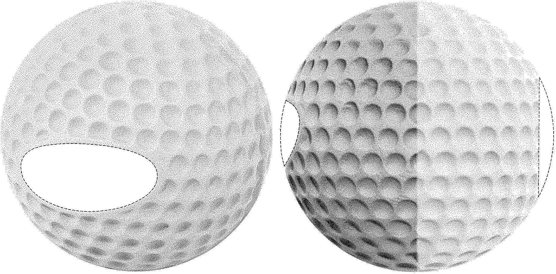
FIG. 1 is a top front perspective view of the ball projectile showing a first embodiment or our new design;
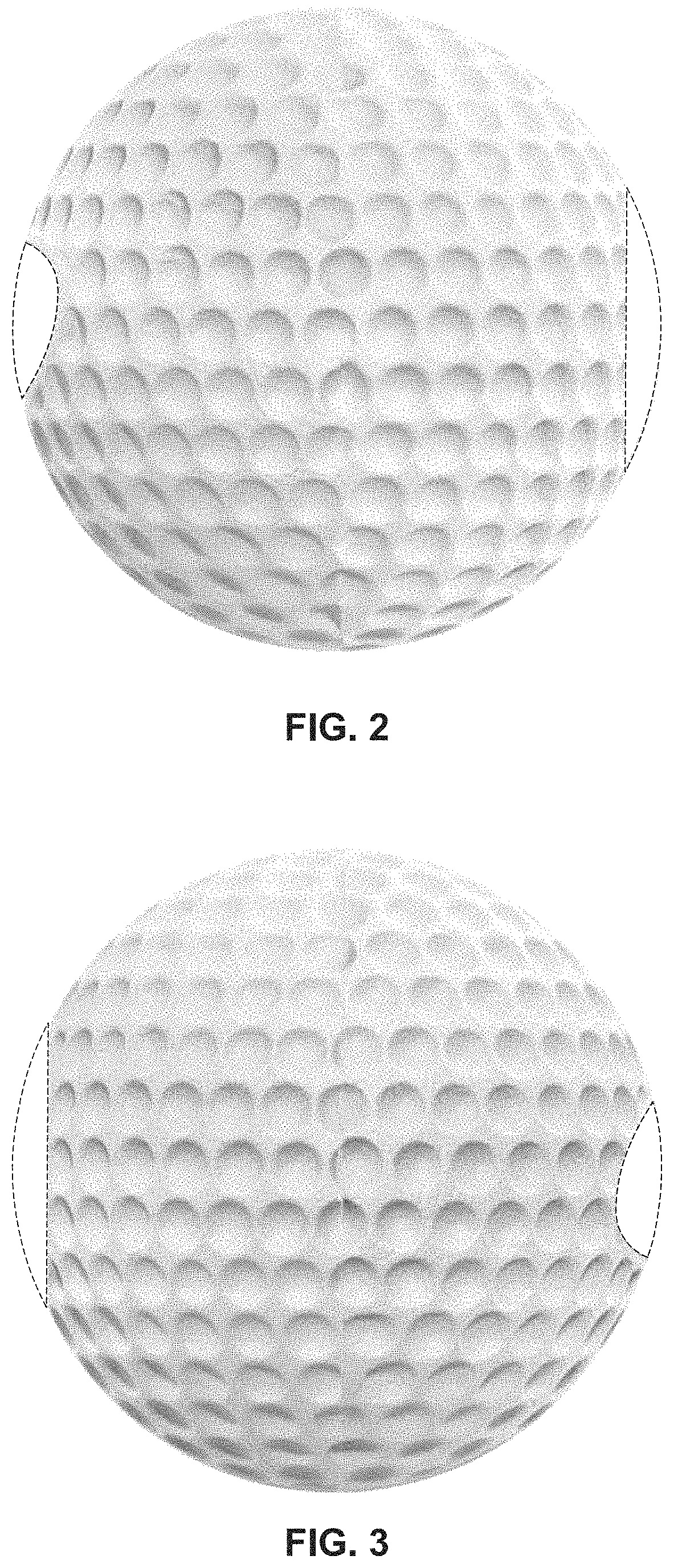
FIG. 2 is a right side elevational view thereof;
FIG. 3 is a left side elevational view thereof;
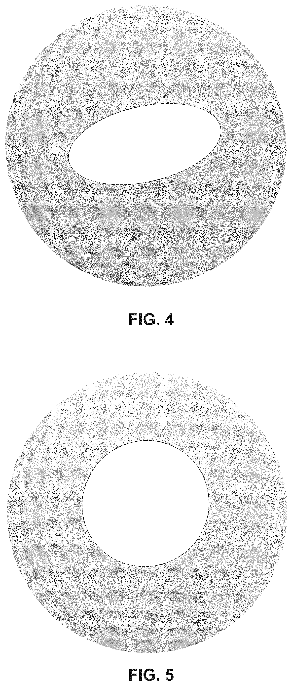
FIG. 4 is a front view thereof;
FIG. 5 is a rear view thereof;
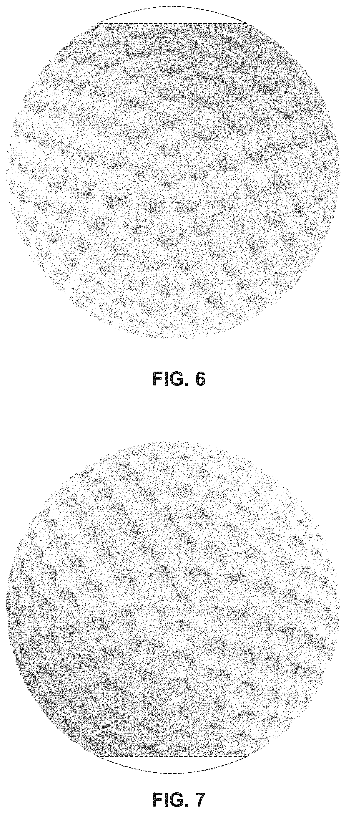
FIG. 6 is a top view thereof;
FIG. 7 is a bottom view thereof;
FIG. 8 is a top front perspective view showing a second embodiment or our new design;
FIG. 9 is a right side elevational view thereof;
FIG. 10 is a left side elevational view thereof;
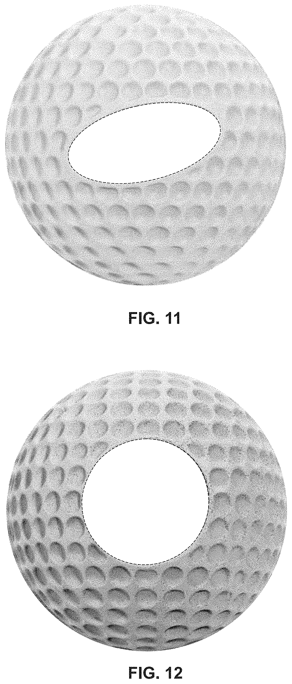
FIG. 11 is a front view thereof;
FIG. 12 is a rear view thereof;
FIG. 13 is a top view thereof;
FIG. 14 is a bottom view thereof;
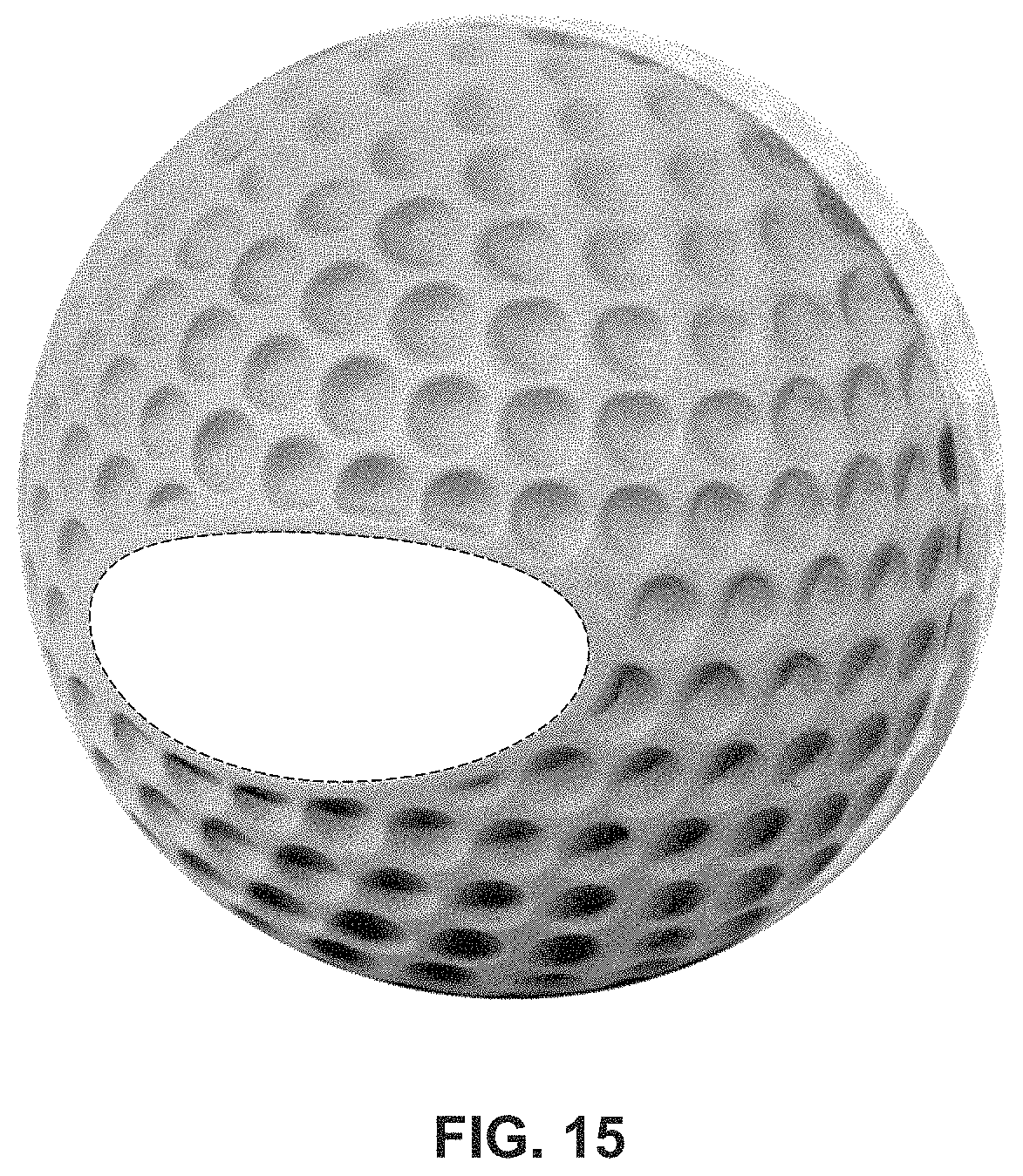
FIG. 15 is a perspective view showing a third embodiment or our new design;
FIG. 16 is a right side elevational view thereof;
FIG. 17 is a left side elevational view thereof;
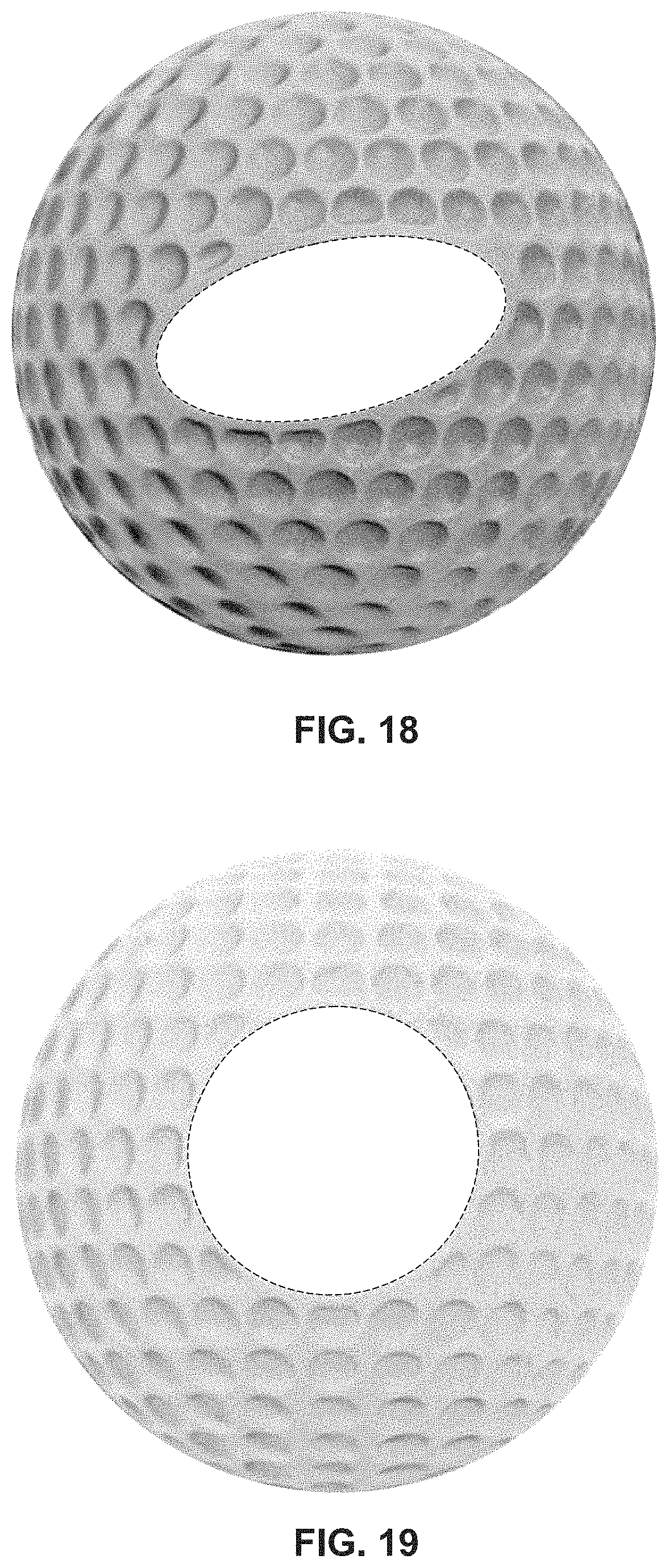
FIG. 18 is a front view thereof;
FIG. 19 is a rear view thereof;
FIG. 20 is a top view thereof; and,
FIG. 21 is a bottom view thereof.
The broken lines shown are included for the purpose of delineating the bounds of the claim adjacent to the unshaded areas.
* * * * *
D00000
D00001
D00002
D00003
D00004
D00005
D00006
D00007
D00008
D00009
D00010
D00011
D00012

XML
uspto.report is an independent third-party trademark research tool that is not affiliated, endorsed, or sponsored by the United States Patent and Trademark Office (USPTO) or any other governmental organization. The information provided by uspto.report is based on publicly available data at the time of writing and is intended for informational purposes only.
While we strive to provide accurate and up-to-date information, we do not guarantee the accuracy, completeness, reliability, or suitability of the information displayed on this site. The use of this site is at your own risk. Any reliance you place on such information is therefore strictly at your own risk.
All official trademark data, including owner information, should be verified by visiting the official USPTO website at www.uspto.gov. This site is not intended to replace professional legal advice and should not be used as a substitute for consulting with a legal professional who is knowledgeable about trademark law.