Automatic card collator with dispenser
Rynda
U.S. patent number D892,219 [Application Number D/640,425] was granted by the patent office on 2020-08-04 for automatic card collator with dispenser. This patent grant is currently assigned to AGS LLC. The grantee listed for this patent is AGS LLC. Invention is credited to Robert John Rynda.


| United States Patent | D892,219 |
| Rynda | August 4, 2020 |
Automatic card collator with dispenser
Claims
CLAIM The ornamental design for an automatic card collator with dispenser, as shown and described.
| Inventors: | Rynda; Robert John (Las Vegas, NV) | ||||||||||
|---|---|---|---|---|---|---|---|---|---|---|---|
| Applicant: |
|
||||||||||
| Assignee: | AGS LLC (Las Vegas,
NV) |
||||||||||
| Appl. No.: | D/640,425 | ||||||||||
| Filed: | March 14, 2018 |
| Current U.S. Class: | D21/300 |
| Current International Class: | 2101 |
| Field of Search: | ;D20/9,76 ;D99/99 ;273/149R ;D21/300,396 |
References Cited [Referenced By]
U.S. Patent Documents
| D224658 | August 1972 | Cole et al. |
| D273962 | May 1984 | Fromm |
| D414527 | September 1999 | Tedham |
| D432588 | October 2000 | Tedham |
| D432589 | October 2000 | Hill |
| 6588751 | July 2003 | Grauzer et al. |
| 6651981 | November 2003 | Grauzer et al. |
| 6651983 | November 2003 | Chobanian |
| 6655684 | December 2003 | Grauzer et al. |
| D488193 | April 2004 | Girard |
| D490481 | May 2004 | Hessing |
| 7036818 | May 2006 | Grauzer et al. |
| 7234698 | June 2007 | Grauzer et al. |
| 7478813 | January 2009 | Hofferber |
| 7677565 | March 2010 | Grauzer et al. |
| D615600 | May 2010 | Scheper et al. |
| D646338 | October 2011 | Scheper et al. |
| 8070574 | December 2011 | Grauzer et al. |
| D663785 | July 2012 | Walsh et al. |
| 8342525 | January 2013 | Scheper et al. |
| 8353513 | January 2013 | Swanson |
| 8480088 | July 2013 | Toyama |
| 8490793 | July 2013 | Yoseloff et al. |
| 8511684 | August 2013 | Grauzer et al. |
| 8579289 | November 2013 | Rynda et al. |
| D695357 | December 2013 | Shigeta |
| 8960674 | February 2015 | Stasson et al. |
| 8986091 | March 2015 | Grauzer et al. |
| D764599 | August 2016 | Tedham |
| 9504905 | November 2016 | Kelly et al. |
| 9539494 | January 2017 | Sines et al. |
| 9566501 | February 2017 | Stasson et al. |
| 9731190 | August 2017 | Sampson et al. |
| D798958 | October 2017 | Tseng |
| 2002/0163125 | November 2002 | Grauzer et al. |
| 2003/0090059 | May 2003 | Grauzer et al. |
| 2004/0245720 | December 2004 | Grauzer et al. |
| 2005/0051956 | March 2005 | Grauzer et al. |
| 2007/0138743 | June 2007 | Fleckenstein |
| 2008/0006997 | January 2008 | Scheper |
| 2008/0093800 | April 2008 | Mailing |
| 2013/0087972 | April 2013 | Snow |
| 2015/0014925 | January 2015 | Miller |
| 2015/0290528 | October 2015 | Sampson |
| 2016/0082344 | March 2016 | Kelly et al. |
| 2017/0173447 | June 2017 | Martino |
| 2017/0326439 | November 2017 | Shigeta |
| 2018/0085658 | March 2018 | Helsen |
| 2019/0105554 | April 2019 | Rouillard |
| 2019/0262694 | August 2019 | Shigeta |
Other References
|
"Automatic Card Shuffler" posted Sep. 23, 2013[online], [retrieved Dec. 26, 2019] from internet: https://www.youtube.com/watch?v=y6Xy6wd5cno. cited by examiner. |
Primary Examiner: Snapp; Sandra S
Assistant Examiner: Bajoul; Mehri F
Attorney, Agent or Firm: Brinks Gilson & Lione
Description
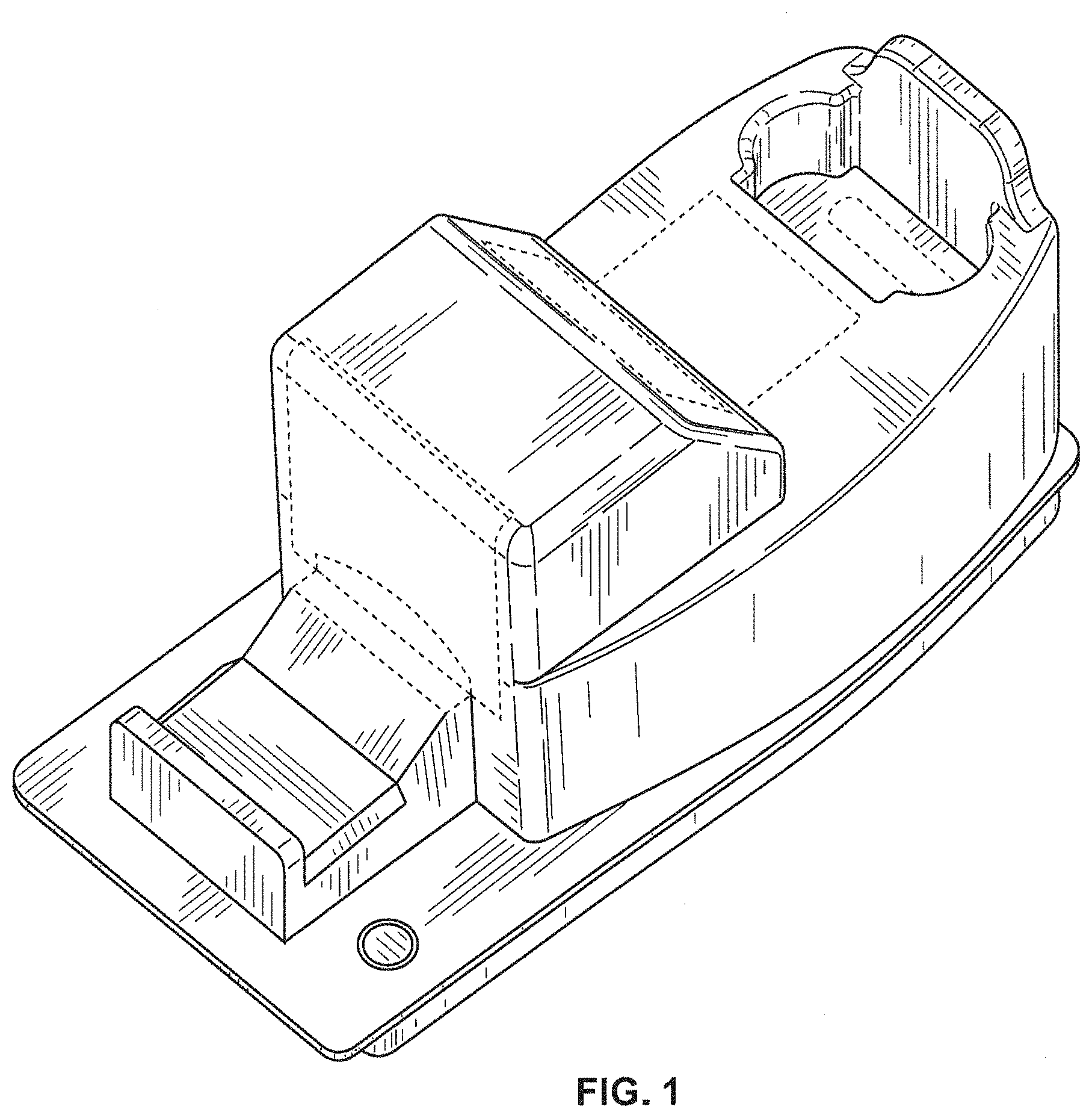
FIG. 1 is a front left perspective view of an automatic card collator with dispenser showing my new design;
FIG. 2 is a front elevational view of the automatic card collator with dispenser shown in FIG. 1;
FIG. 3 is a rear elevational view of the automatic card collator with dispenser shown in FIG. 1;
FIG. 4 is a left right side elevational view of the automatic card collator with dispenser shown in FIG. 1;
FIG. 5 is a left right side elevational view of the automatic card collator with dispenser shown in FIG. 1;
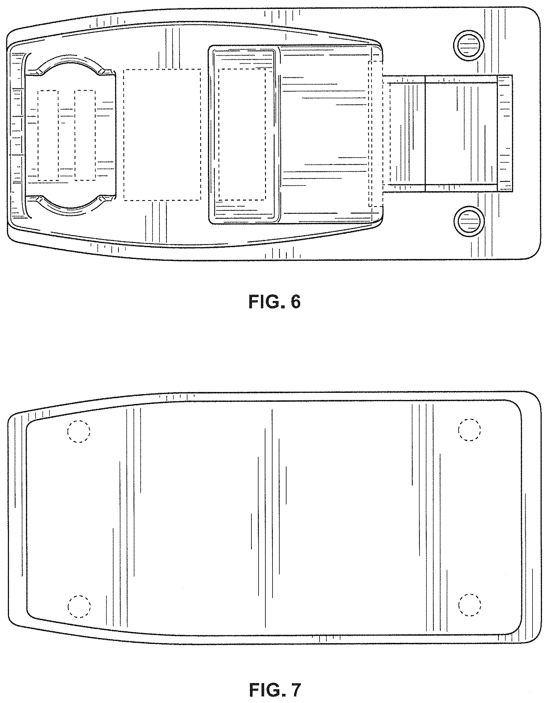
FIG. 6 is a top plan view of the automatic card collator with dispenser shown in FIG. 1;
FIG. 7 is a bottom plan view of the automatic card collator with dispenser shown in FIG. 1;
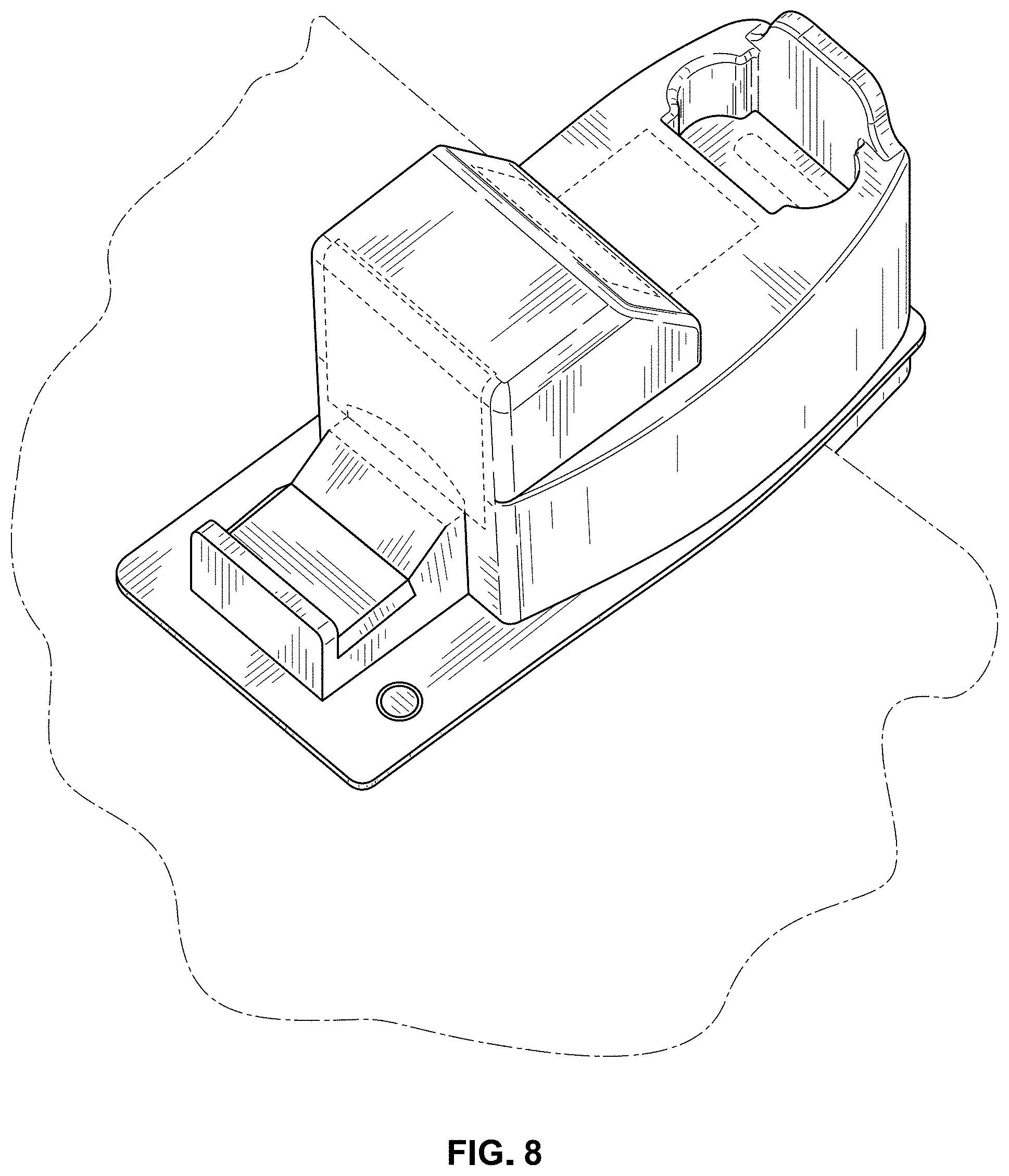
FIG. 8 is a front left perspective view of the automatic card collator with dispenser shown in the environment of use, inserted into an aperture in an edge of a table top edge, where the table top is shown in dash-dot broken line; and,
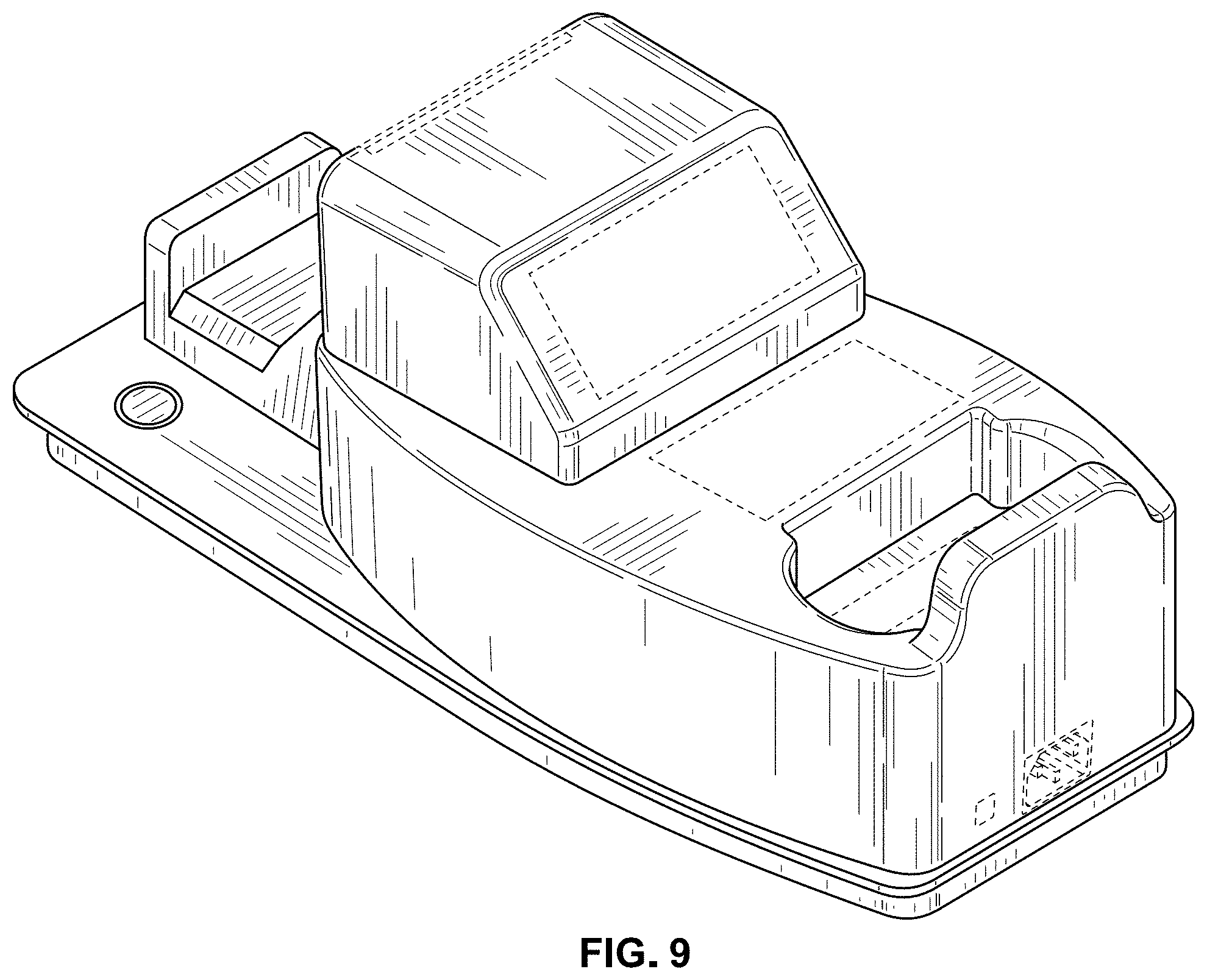
FIG. 9 is a rear left perspective view of the automatic card collator with dispenser shown in FIG. 1.
The evenly dashed broken lines depict portions for the automatic card collator with dispenser that form no part of the claimed design; and the dash-dot broken lines in FIG. 8 depict environmental structure that forms no part of the claimed design.
* * * * *
References
D00000
D00001
D00002
D00003
D00004
D00005
D00006
XML
uspto.report is an independent third-party trademark research tool that is not affiliated, endorsed, or sponsored by the United States Patent and Trademark Office (USPTO) or any other governmental organization. The information provided by uspto.report is based on publicly available data at the time of writing and is intended for informational purposes only.
While we strive to provide accurate and up-to-date information, we do not guarantee the accuracy, completeness, reliability, or suitability of the information displayed on this site. The use of this site is at your own risk. Any reliance you place on such information is therefore strictly at your own risk.
All official trademark data, including owner information, should be verified by visiting the official USPTO website at www.uspto.gov. This site is not intended to replace professional legal advice and should not be used as a substitute for consulting with a legal professional who is knowledgeable about trademark law.