Orthopedic implant
Cheney
U.S. patent number D891,618 [Application Number D/710,576] was granted by the patent office on 2020-07-28 for orthopedic implant. This patent grant is currently assigned to DePuy Synthes Products, Inc.. The grantee listed for this patent is DEPUY SYNTHES PRODUCTS, INC.. Invention is credited to Daniel F. Cheney.


View All Diagrams
| United States Patent | D891,618 |
| Cheney | July 28, 2020 |
Orthopedic implant
Claims
CLAIM The ornamental design for an orthopedic implant, as shown and described.
| Inventors: | Cheney; Daniel F. (Downingtown, PA) | ||||||||||
|---|---|---|---|---|---|---|---|---|---|---|---|
| Applicant: |
|
||||||||||
| Assignee: | DePuy Synthes Products, Inc.
(Raynham, MA) |
||||||||||
| Family ID: | 66170312 | ||||||||||
| Appl. No.: | D/710,576 | ||||||||||
| Filed: | October 24, 2019 |
Related U.S. Patent Documents
| Application Number | Filing Date | Patent Number | Issue Date | ||
|---|---|---|---|---|---|
| 15844133 | Dec 15, 2017 | ||||
| Current U.S. Class: | D24/155 |
| Current CPC Class: | A61B17/10 20130101; A61B17/0644 20130101; A61B17/0682 20130101; A61B17/0642 20130101; A61B2017/0641 20130101; A61B2017/0645 20130101; A61B2017/00867 20130101 |
| Current International Class: | 2403 |
| Field of Search: | ;D24/155-157 ;D8/390 |
References Cited [Referenced By]
U.S. Patent Documents
| 3939828 | February 1976 | Mohr |
| 5246443 | September 1993 | Mai |
| D484032 | December 2003 | Del Re |
| D586915 | February 2009 | Grim |
| D691720 | October 2013 | Cheney et al. |
| D707357 | June 2014 | Cheney |
| 9402624 | August 2016 | Scott |
| D773666 | December 2016 | Cheney et al. |
| D780311 | February 2017 | Cheney |
| 9901338 | February 2018 | Anderson |
| D865178 | October 2019 | Sammarco |
| 10456130 | October 2019 | Cheney |
| D870284 | December 2019 | Hollis |
| 2002/0019636 | February 2002 | Ogilvie |
| 2013/0231667 | September 2013 | Taylor |
| 2014/0018809 | January 2014 | Allen |
| 2014/0039561 | February 2014 | Weiner et al. |
| 2016/0066907 | March 2016 | Cheney et al. |
Attorney, Agent or Firm: Makay; Christopher L.
Description
FIG. 1 is a perspective view of the orthopedic implant according to a first embodiment;
FIG. 2 is a right side view thereof;
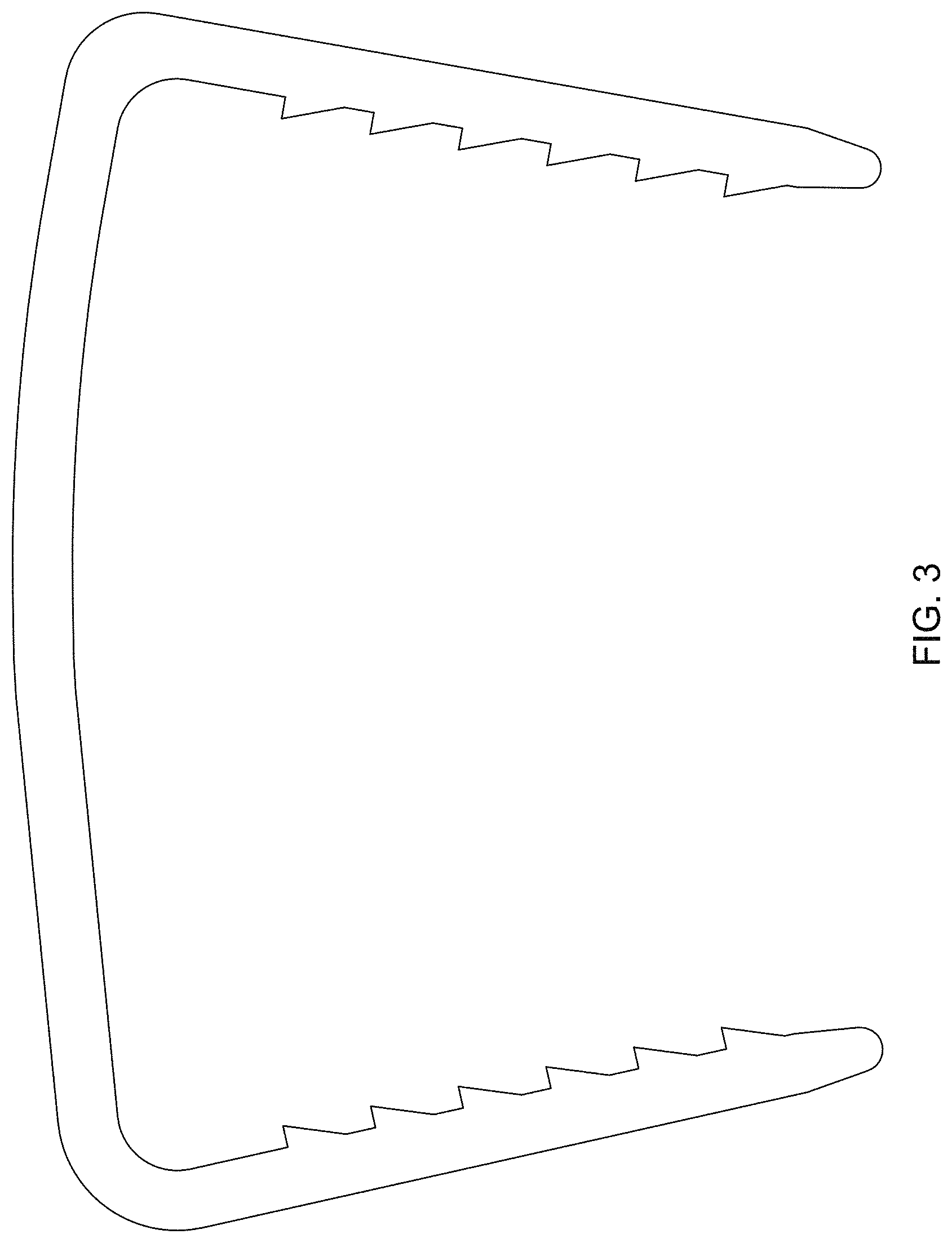
FIG. 3 is a left side view thereof;
FIG. 4 is a top view thereof;
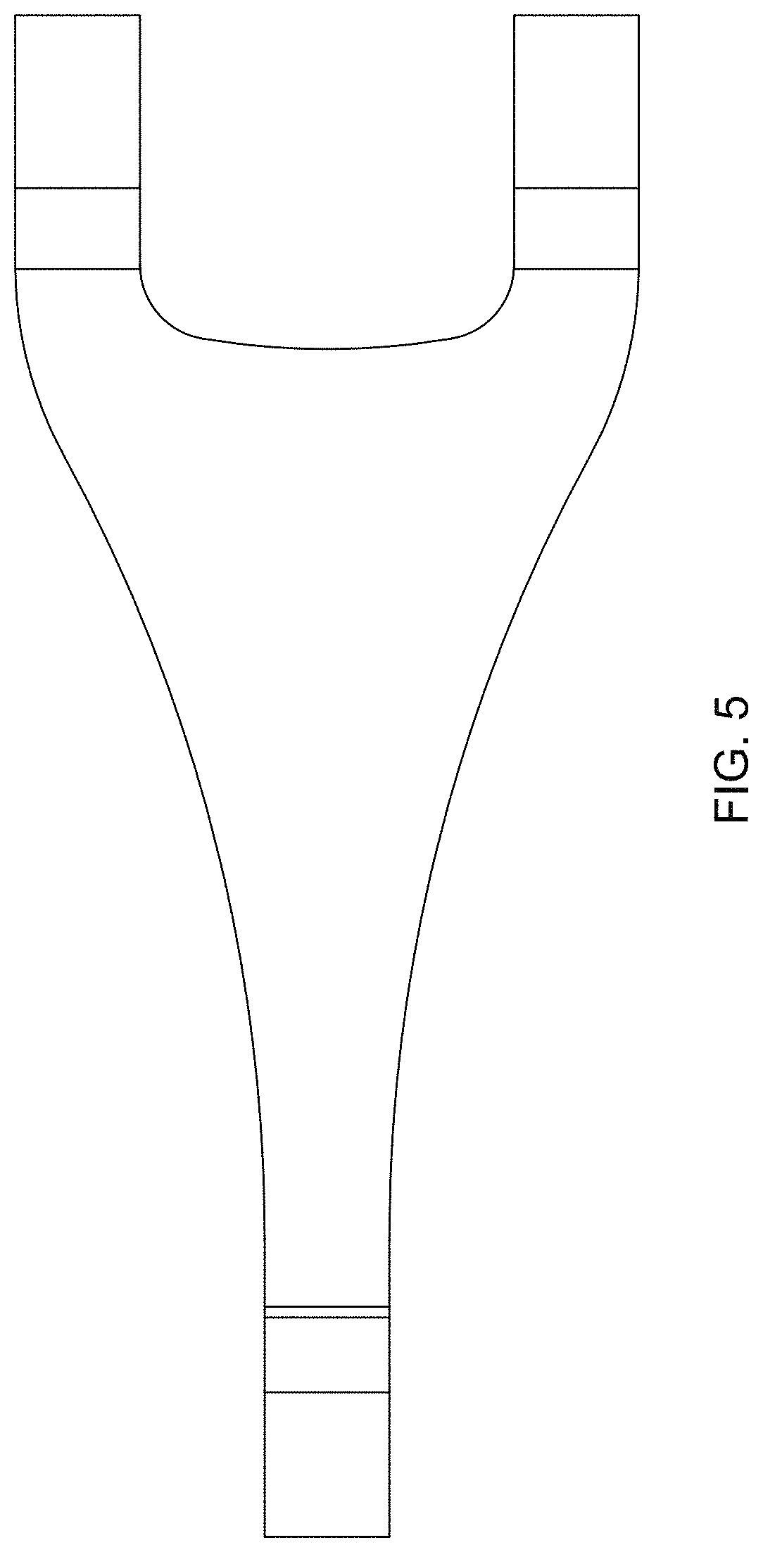
FIG. 5 is a bottom view thereof;
FIG. 6 is a front view thereof;
FIG. 7 is a rear view thereof;
FIG. 8 is a perspective view of the orthopedic implant according to a second embodiment;
FIG. 9 is a right side view thereof;
FIG. 10 is a left side view thereof;
FIG. 11 is a top view thereof;
FIG. 12 is a bottom view thereof;
FIG. 13 is a front view thereof; and,
FIG. 14 is a rear view thereof.
* * * * *
D00000
D00001
D00002
D00003
D00004
D00005
D00006
D00007
D00008
D00009
D00010
D00011
D00012

D00013

D00014

XML
uspto.report is an independent third-party trademark research tool that is not affiliated, endorsed, or sponsored by the United States Patent and Trademark Office (USPTO) or any other governmental organization. The information provided by uspto.report is based on publicly available data at the time of writing and is intended for informational purposes only.
While we strive to provide accurate and up-to-date information, we do not guarantee the accuracy, completeness, reliability, or suitability of the information displayed on this site. The use of this site is at your own risk. Any reliance you place on such information is therefore strictly at your own risk.
All official trademark data, including owner information, should be verified by visiting the official USPTO website at www.uspto.gov. This site is not intended to replace professional legal advice and should not be used as a substitute for consulting with a legal professional who is knowledgeable about trademark law.