Architectural screen
Schneider , et al.
U.S. patent number D889,688 [Application Number D/664,581] was granted by the patent office on 2020-07-07 for architectural screen. This patent grant is currently assigned to BARRETTE OUTDOOR LIVING, INC.. The grantee listed for this patent is BARRETTE OUTDOOR LIVING, INC.. Invention is credited to Patrick Joseph Bertke, James Joseph Powers, Christopher Michael Schneider.


| United States Patent | D889,688 |
| Schneider , et al. | July 7, 2020 |
Architectural screen
Claims
CLAIM The ornamental design for an architectural screen, as shown and described.
| Inventors: | Schneider; Christopher Michael (Middleburg Heights, OH), Bertke; Patrick Joseph (Middleburg Heights, OH), Powers; James Joseph (Middleburg Heights, OH) | ||||||||||
|---|---|---|---|---|---|---|---|---|---|---|---|
| Applicant: |
|
||||||||||
| Assignee: | BARRETTE OUTDOOR LIVING, INC.
(Middleburg Heights, unknown) |
||||||||||
| Appl. No.: | D/664,581 | ||||||||||
| Filed: | September 26, 2018 |
| Current U.S. Class: | D25/58 |
| Current International Class: | 2501 |
| Field of Search: | ;D5/1-6,8,11,12,15,16,24,29,32,43,47,53,54,58,59,60,62 ;D25/38.1,40,58,138,149,152,153,156,157,158,159,160,161,162 |
References Cited [Referenced By]
U.S. Patent Documents
| 519663 | May 1894 | Carr |
| 538040 | April 1895 | Hilton |
| D40039 | June 1909 | Schmidt |
| 2945315 | July 1960 | Stockton |
| D193238 | July 1962 | Chavatel |
| D200048 | January 1965 | Van Dyck |
| D201872 | August 1965 | Mezey et al. |
| D206374 | December 1966 | Barnett |
| 3312029 | April 1967 | Blum |
| 3417532 | December 1968 | Blum |
| 3935671 | February 1976 | Soot |
| D257177 | September 1980 | Demarest |
| D464740 | October 2002 | Griffith |
| D559565 | January 2008 | Bakker |
| D843605 | March 2019 | Schneider |
| D843606 | March 2019 | Schneider |
| D843607 | March 2019 | Schneider |
| D843608 | March 2019 | Schneider |
| D872304 | January 2020 | Naylor |
| D872305 | January 2020 | Naylor |
| 2010/0283022 | November 2010 | Delafield |
| 2016/0201352 | July 2016 | Mouchet |
| 2019/0127987 | May 2019 | Schneider |
| 005940822-0003 | Jan 2019 | EM | |||
Other References
|
Decorative Screen Panels--Xpanse Greater Outdoors https://www.xpansegreateroutdoors.com/products/decorative-accents/decorat- ive-screen-panels/ Feb. 2017 (Year: 2017). cited by examiner. |
Primary Examiner: Was-Englehart; Leanne
Attorney, Agent or Firm: Maldjian; John Maldjian Law Group LLC
Description
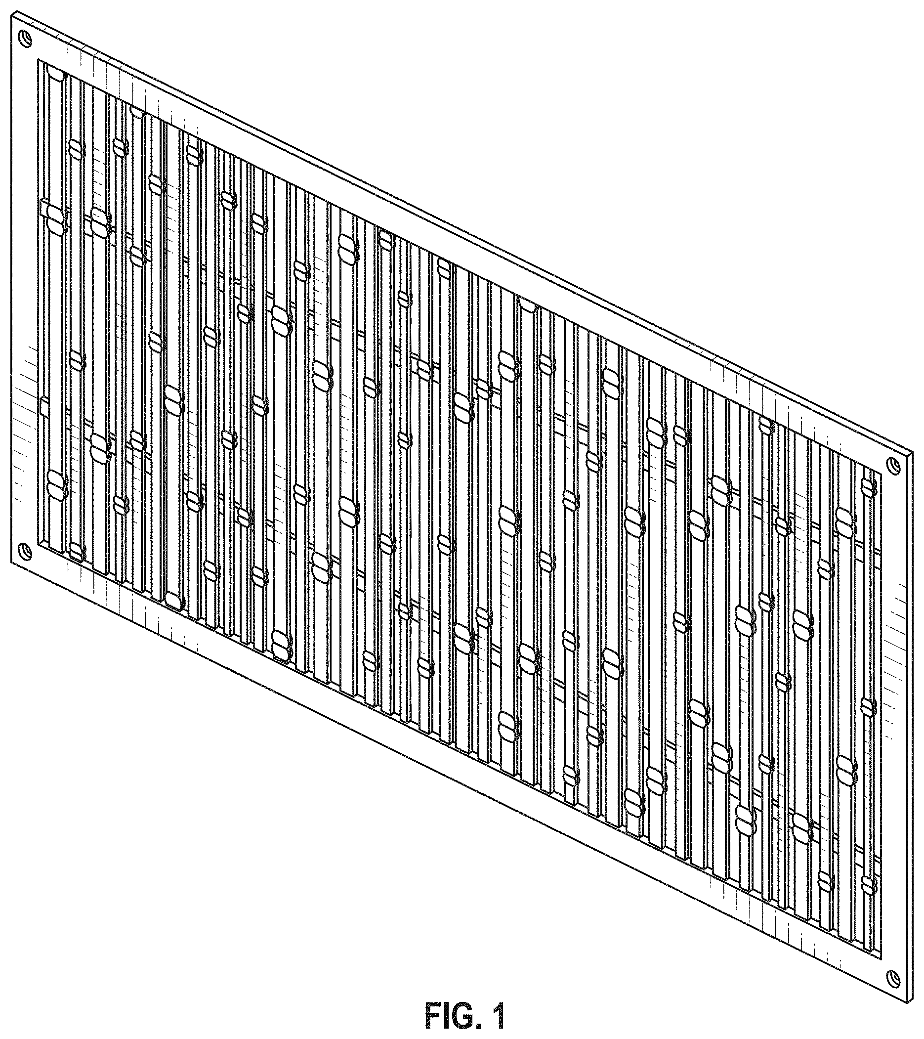
FIG. 1 is a perspective view of an architectural screen showing our new design;
FIG. 2 is a front elevation view thereof;
FIG. 3 is a rear elevation view thereof;
FIG. 4 is a left side elevation view thereof;
FIG. 5 is a right side elevation view thereof;
FIG. 6 is a top plan view thereof; and,
FIG. 7 is a bottom plan view thereof.
* * * * *
References
D00000
D00001
D00002
D00003
D00004
XML
uspto.report is an independent third-party trademark research tool that is not affiliated, endorsed, or sponsored by the United States Patent and Trademark Office (USPTO) or any other governmental organization. The information provided by uspto.report is based on publicly available data at the time of writing and is intended for informational purposes only.
While we strive to provide accurate and up-to-date information, we do not guarantee the accuracy, completeness, reliability, or suitability of the information displayed on this site. The use of this site is at your own risk. Any reliance you place on such information is therefore strictly at your own risk.
All official trademark data, including owner information, should be verified by visiting the official USPTO website at www.uspto.gov. This site is not intended to replace professional legal advice and should not be used as a substitute for consulting with a legal professional who is knowledgeable about trademark law.