Distributor plate assembly
Fangman , et al.
U.S. patent number D889,595 [Application Number D/668,918] was granted by the patent office on 2020-07-07 for distributor plate assembly. This patent grant is currently assigned to Ecowater Systems LLC. The grantee listed for this patent is Ecowater Systems LLC. Invention is credited to George L. Dimotsis, Christopher James Fangman, Malcolm Kahn, Mark Joseph Sowada.


| United States Patent | D889,595 |
| Fangman , et al. | July 7, 2020 |
Distributor plate assembly
Claims
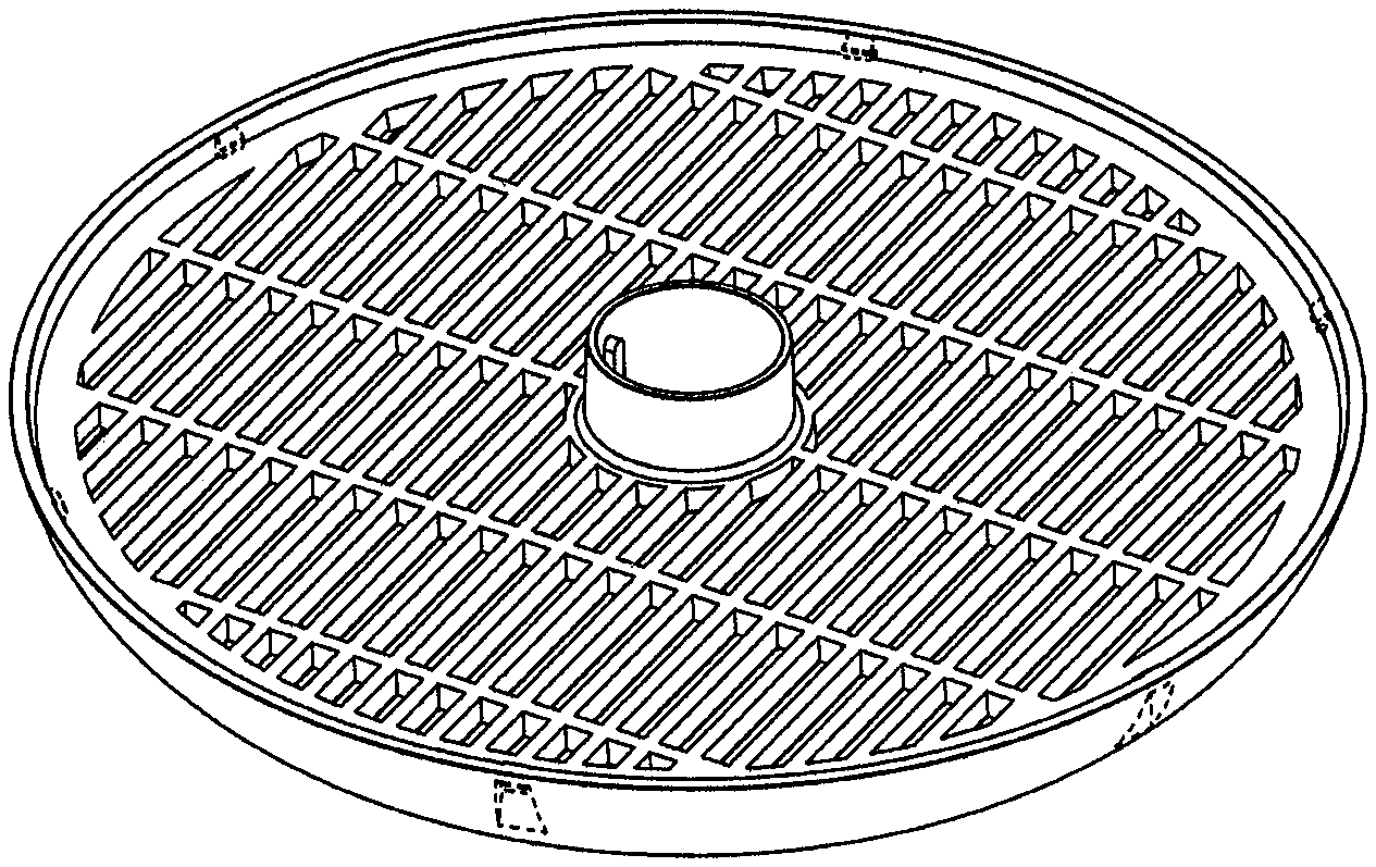
CLAIM The ornamental design for a "distributor plate assembly", as shown and described.
| Inventors: | Fangman; Christopher James (Red Wing, MN), Dimotsis; George L. (Woodbury, MN), Sowada; Mark Joseph (Plymouth, MN), Kahn; Malcolm (Franklin Lakes, NJ) | ||||||||||
|---|---|---|---|---|---|---|---|---|---|---|---|
| Applicant: |
|
||||||||||
| Assignee: | Ecowater Systems LLC (Woodbury,
MN) |
||||||||||
| Appl. No.: | D/668,918 | ||||||||||
| Filed: | November 2, 2018 |
| Current U.S. Class: | D23/207 |
| Current International Class: | 2301 |
| Field of Search: | ;D23/202,203,205,206,207,209,233,235,336,365,366 |
References Cited [Referenced By]
U.S. Patent Documents
| 2204158 | June 1940 | Serio |
| 5378370 | January 1995 | Brane et al. |
| D372079 | July 1996 | Fago |
| 7100262 | September 2006 | Carter |
| 7354495 | April 2008 | Carter et al. |
| 7407062 | August 2008 | Carter |
| D591823 | May 2009 | Stolarik et al. |
| D625772 | October 2010 | Olson |
| 7810670 | October 2010 | Carter et al. |
| 7901576 | March 2011 | Stolarik et al. |
| 7963400 | June 2011 | Stolarik et al. |
| 8110103 | February 2012 | Mormino et al. |
| D666272 | August 2012 | Shi |
| D669155 | October 2012 | Bryan |
| D674464 | January 2013 | Wilder |
| 8382994 | February 2013 | Stolarik et al. |
| D712508 | September 2014 | Du |
| 9180391 | November 2015 | Horner et al. |
| 9815010 | November 2017 | Horner et al. |
| 2005/0006393 | January 2005 | Carter |
| 2006/0060289 | March 2006 | Carter et al. |
| 2006/0289546 | December 2006 | Carter |
| 2008/0149636 | June 2008 | Carter et al. |
| 2009/0039009 | February 2009 | Stolarik et al. |
| 2013/0062266 | March 2013 | Horner et al. |
| 2017/0319992 | November 2017 | Horner et al. |
| 1601902 | Dec 2005 | EP | |||
| 1434962 | Nov 2010 | EP | |||
Other References
|
Zhe Tan, Shengfu Chen, Xinsheng Peng, Lin Zhang, Congjie Gao; "Polyamide Membranes With Nanoscale Turing Structures for Water Purification"; Science 360, p. 518-521 (2018), May 4, 2018. cited by applicant . Alan Turing; "A Membrane That Can Remove Salts From Water More Efficiently"; Science and Technology, May 3, 2018. cited by applicant. |
Primary Examiner: Lane; Sheryl
Assistant Examiner: Vansant; Calvin E
Attorney, Agent or Firm: DeLio Peterson & Curcio LLC Curcio; Robert
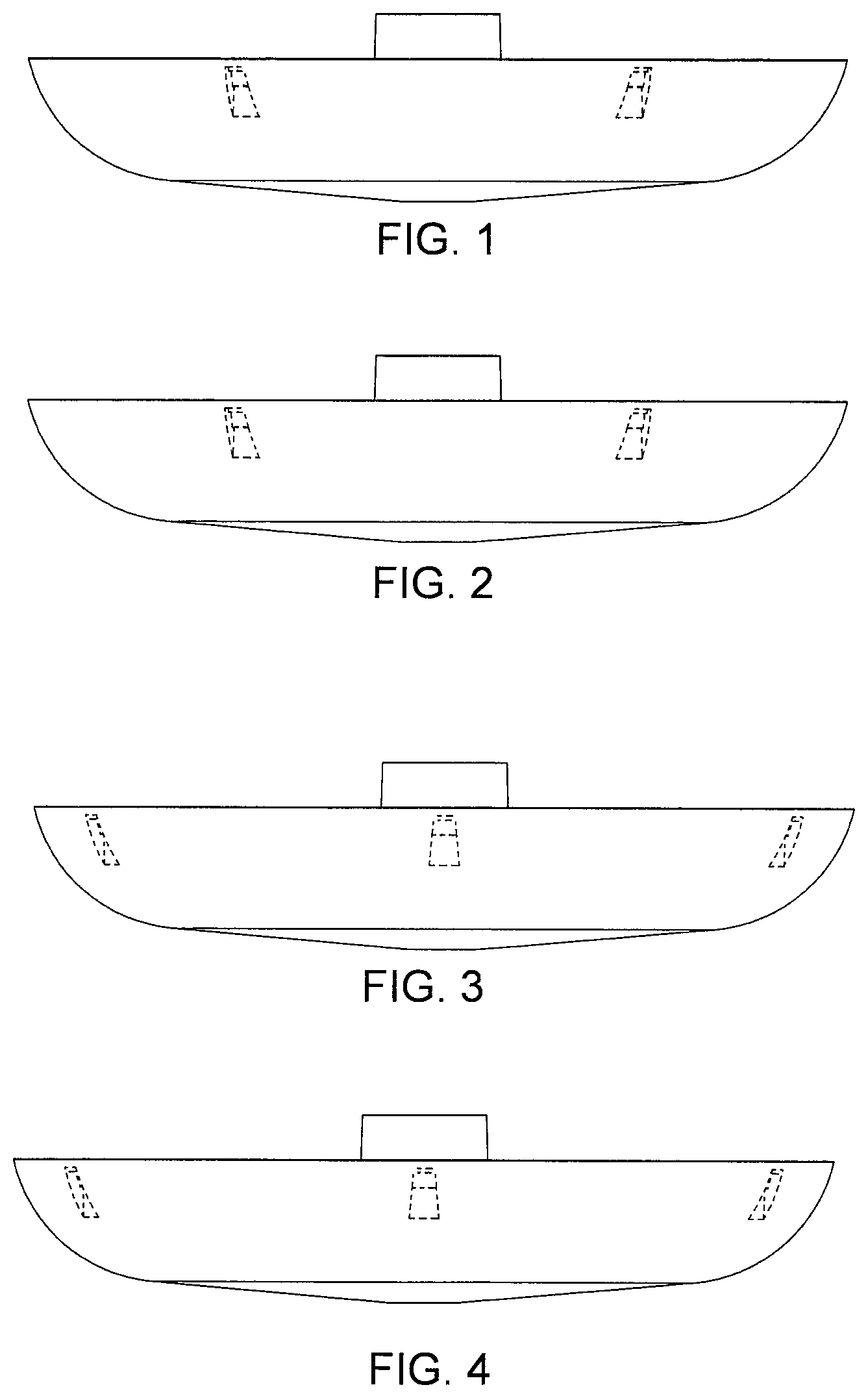
Description
FIG. 1 is a front elevational view of the "distributor plate assembly" design according to our invention;
FIG. 2 is a back elevational view of the "distributor plate assembly" shown in FIG. 1;
FIG. 3 is a right elevational view of the "distributor plate assembly" shown in FIG. 1;
FIG. 4 is a left elevational view of the "distributor plate assembly" shown in FIG. 1;
FIG. 5 is a top view of the "distributor plate assembly" shown in FIG. 1;
FIG. 6 is a bottom view of the "distributor plate assembly" shown in FIG. 1;
FIG. 7 is a top perspective view of the "distributor plate assembly" shown in FIG. 1; and,
FIG. 8 is a bottom perspective view of the "distributor plate assembly" shown in FIG. 1.
The broken lines represent portions of the distributor plate assembly that form no part of the claimed design.
* * * * *
D00000
D00001
D00002
D00003
XML
uspto.report is an independent third-party trademark research tool that is not affiliated, endorsed, or sponsored by the United States Patent and Trademark Office (USPTO) or any other governmental organization. The information provided by uspto.report is based on publicly available data at the time of writing and is intended for informational purposes only.
While we strive to provide accurate and up-to-date information, we do not guarantee the accuracy, completeness, reliability, or suitability of the information displayed on this site. The use of this site is at your own risk. Any reliance you place on such information is therefore strictly at your own risk.
All official trademark data, including owner information, should be verified by visiting the official USPTO website at www.uspto.gov. This site is not intended to replace professional legal advice and should not be used as a substitute for consulting with a legal professional who is knowledgeable about trademark law.