Alternator bracket
Hudnall , et al.
U.S. patent number D889,512 [Application Number D/658,717] was granted by the patent office on 2020-07-07 for alternator bracket. This patent grant is currently assigned to Holley Performance Products, Inc.. The grantee listed for this patent is Holley Performance Products, Inc.. Invention is credited to Coy Hudnall, Kevin Tracy.


View All Diagrams
| United States Patent | D889,512 |
| Hudnall , et al. | July 7, 2020 |
Alternator bracket
Claims
CLAIM The ornamental design for an alternator bracket, as shown and described.
| Inventors: | Hudnall; Coy (Bowling Green, KY), Tracy; Kevin (Port Charlotte, FL) | ||||||||||
|---|---|---|---|---|---|---|---|---|---|---|---|
| Applicant: |
|
||||||||||
| Assignee: | Holley Performance Products,
Inc. (Bowling Green, KY) |
||||||||||
| Appl. No.: | D/658,717 | ||||||||||
| Filed: | August 2, 2018 |
| Current U.S. Class: | D15/5 |
| Current International Class: | 1501 |
| Field of Search: | ;D15/1-9,143 ;D23/231,232,225 ;D12/160,159,223,114,162 ;D8/14,349,354,382,499,364 |
References Cited [Referenced By]
U.S. Patent Documents
| D250805 | January 1979 | Mygind |
| D330154 | October 1992 | Wagner |
| D600720 | September 2009 | Iwanicki |
| 8511272 | August 2013 | Koyama |
| 2009/0159038 | June 2009 | Koyama |
| 2015/0061421 | March 2015 | Yano |
| 2015/0251536 | September 2015 | Sullivan |
| 2019/0242328 | August 2019 | Gillespie |
| 2019/0345893 | November 2019 | Howard |
| 201910219 | Mar 2019 | AU | |||
| 201911577 | Apr 2019 | AU | |||
Other References
|
Holley, 2017 New & Hot Products Catalog, 4 pages, 2016. cited by applicant . IP Australia, Formalities Notice No. 1 for application No. 201910219 dated Feb. 25, 2019. cited by applicant. |
Primary Examiner: Aman; Ania
Attorney, Agent or Firm: Middleton Reutlinger
Description
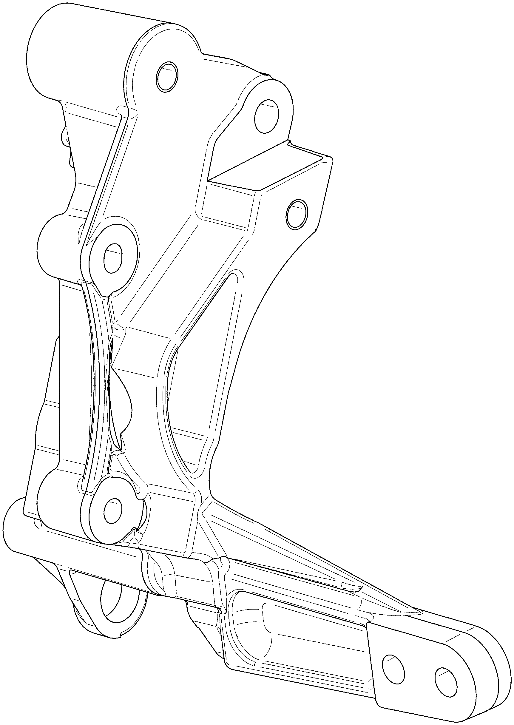
FIG. 1 is a first perspective view of a first design of an alternator bracket;
FIG. 2 is a second perspective of the design of FIG. 1;
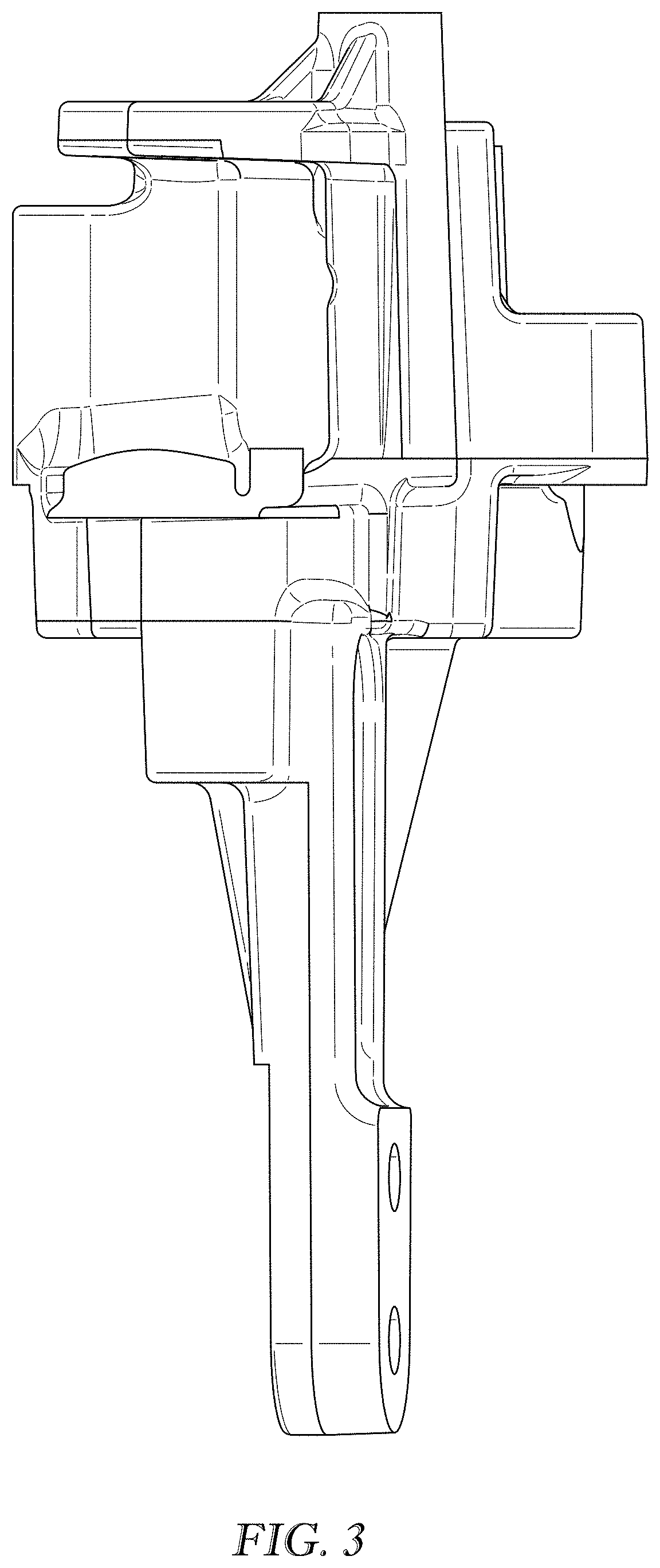
FIG. 3 is a top view of the design of FIG. 1;
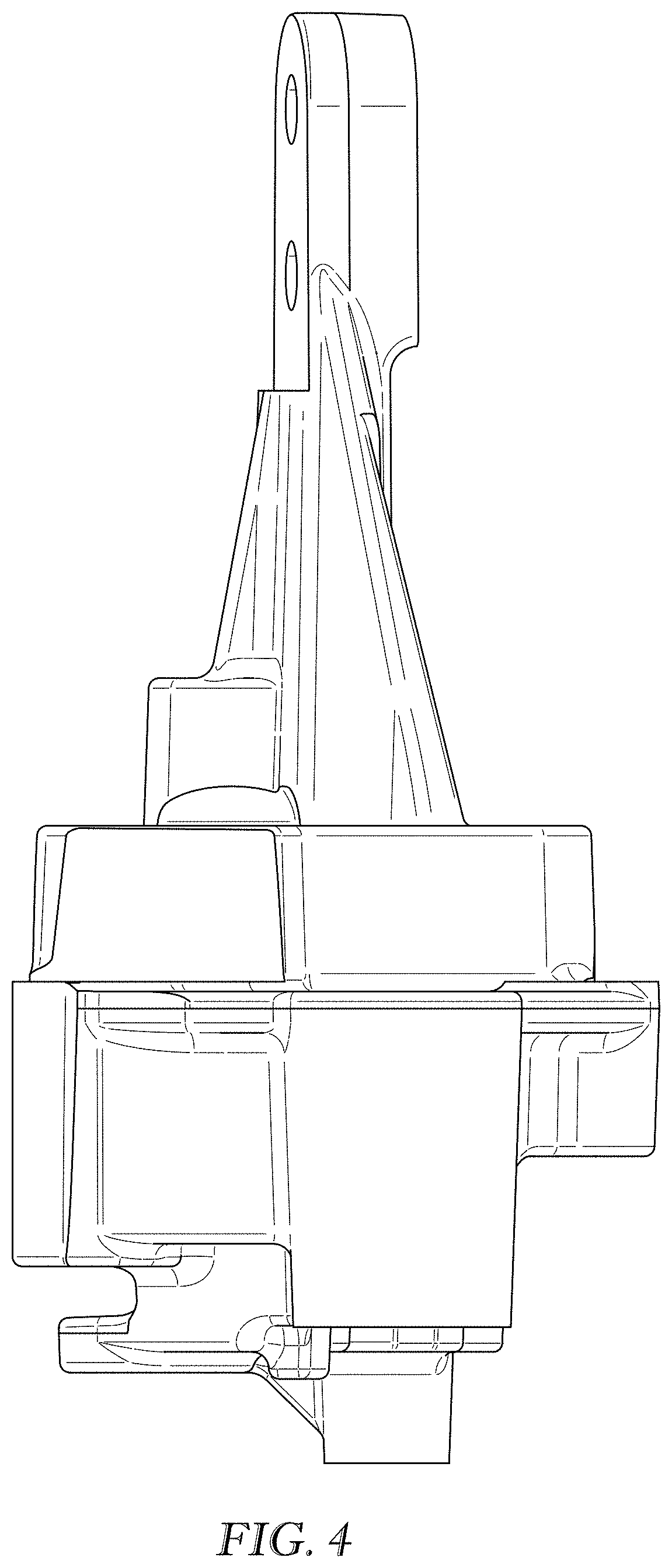
FIG. 4 is a bottom view of the design of FIG. 1;
FIG. 5 is a left side view of the design of FIG. 1;
FIG. 6 is a right side of the design of FIG. 1;
FIG. 7 is a front view of the design of FIG. 1;
FIG. 8 is a rear view of the design of FIG. 1;
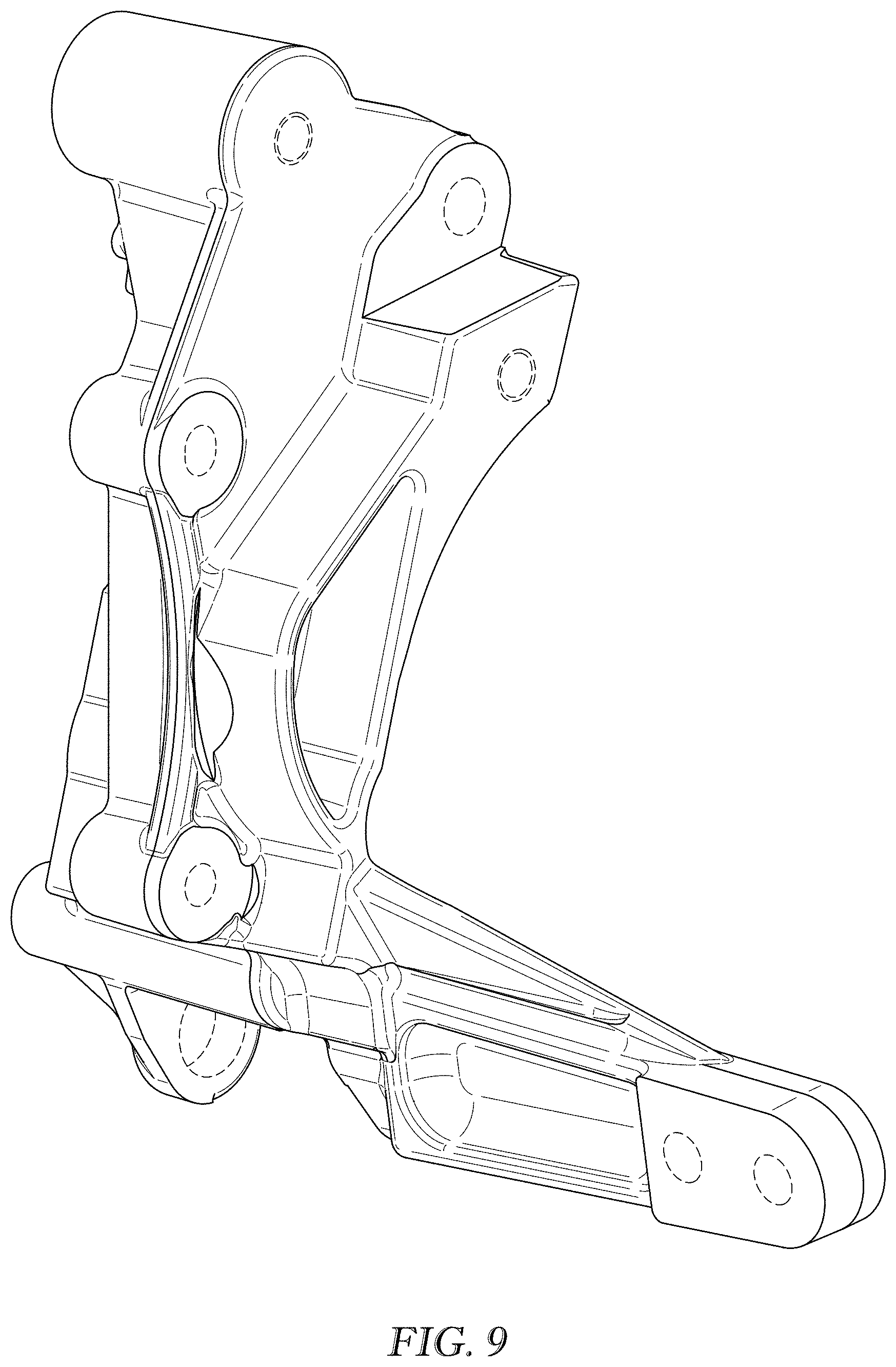
FIG. 9 is a first perspective view of a second design of an alternator bracket;
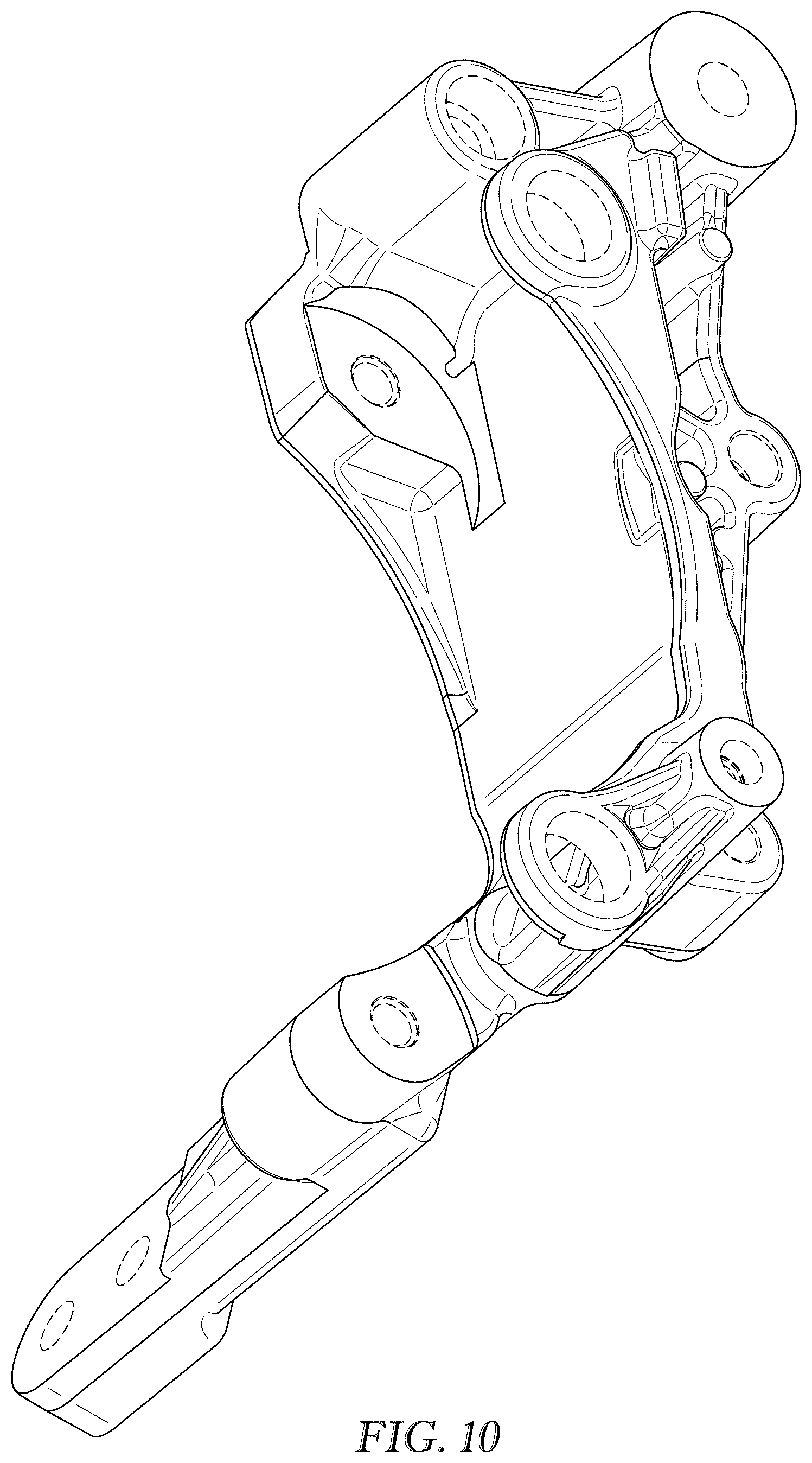
FIG. 10 is a second perspective of the design of FIG. 9;
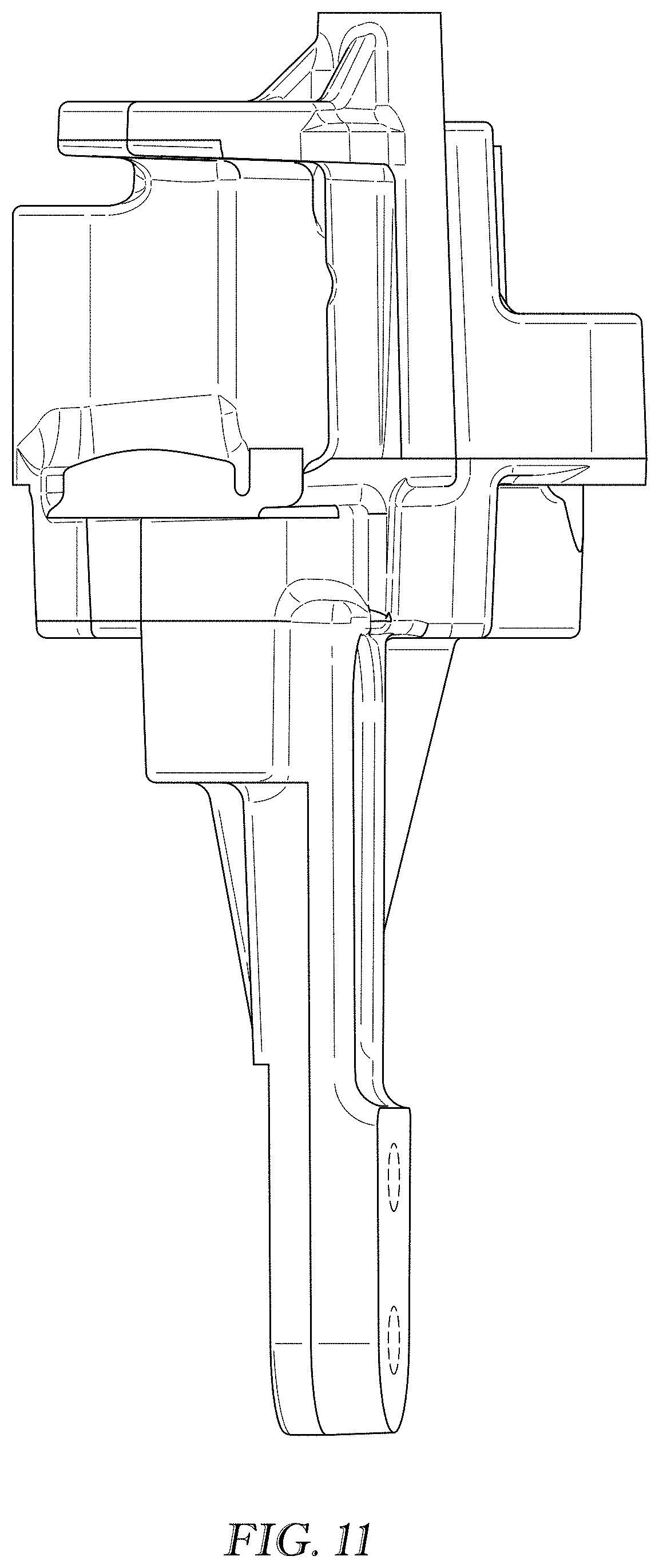
FIG. 11 is a top view of the design of FIG. 9;
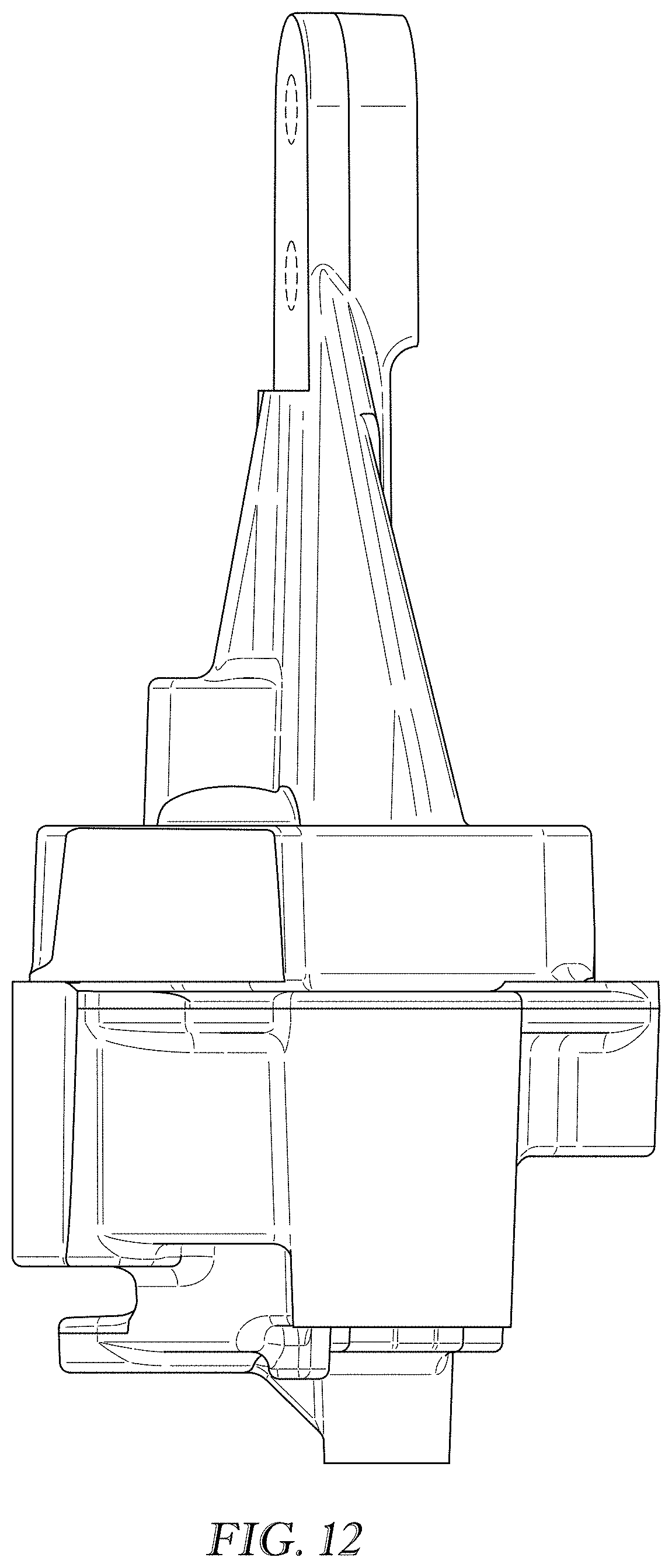
FIG. 12 is a bottom view of the design of FIG. 9;
FIG. 13 is a left side view of the design of FIG. 9;
FIG. 14 is a right side of the design of FIG. 9;
FIG. 15 is a front view of the design of FIG. 9; and,
FIG. 16 is a rear view of the design of FIG. 9.
The broken lines shown in the drawings are for the purpose of illustrating portions of the article and form no part of the claimed design.
* * * * *
D00000
D00001
D00002
D00003
D00004
D00005
D00006
D00007
D00008
D00009
D00010
D00011
D00012
D00013

D00014

D00015

D00016

XML
uspto.report is an independent third-party trademark research tool that is not affiliated, endorsed, or sponsored by the United States Patent and Trademark Office (USPTO) or any other governmental organization. The information provided by uspto.report is based on publicly available data at the time of writing and is intended for informational purposes only.
While we strive to provide accurate and up-to-date information, we do not guarantee the accuracy, completeness, reliability, or suitability of the information displayed on this site. The use of this site is at your own risk. Any reliance you place on such information is therefore strictly at your own risk.
All official trademark data, including owner information, should be verified by visiting the official USPTO website at www.uspto.gov. This site is not intended to replace professional legal advice and should not be used as a substitute for consulting with a legal professional who is knowledgeable about trademark law.