Camera accessory mount
Boerup
U.S. patent number D888,813 [Application Number D/706,194] was granted by the patent office on 2020-06-30 for camera accessory mount. This patent grant is currently assigned to MGMD BrainPower LLC. The grantee listed for this patent is MGMD BrainPower LLC. Invention is credited to Spencer Boerup.


| United States Patent | D888,813 |
| Boerup | June 30, 2020 |
Camera accessory mount
Claims
CLAIM The ornamental design for a camera accessory mount, as shown and described.
| Inventors: | Boerup; Spencer (Tucson, AZ) | ||||||||||
|---|---|---|---|---|---|---|---|---|---|---|---|
| Applicant: |
|
||||||||||
| Assignee: | MGMD BrainPower LLC (Tucson,
AZ) |
||||||||||
| Appl. No.: | D/706,194 | ||||||||||
| Filed: | September 18, 2019 |
Related U.S. Patent Documents
| Application Number | Filing Date | Patent Number | Issue Date | ||
|---|---|---|---|---|---|
| 29654365 | Jun 22, 2018 | ||||
| Current U.S. Class: | D16/242 |
| Current International Class: | 1605 |
| Field of Search: | ;D16/219,237-250 ;D8/354,355,363,373,382-383,394-396 ;D14/224,229,238,251,253,356,447,451,457 |
References Cited [Referenced By]
U.S. Patent Documents
| D515614 | February 2006 | Speggiorin |
| D527992 | September 2006 | Chiang |
| 7563038 | July 2009 | Hershenzon |
| D704713 | May 2014 | Liniger |
| 9158181 | October 2015 | Baker |
| D774382 | December 2016 | Richter |
| D784997 | April 2017 | Cheng |
| D797748 | September 2017 | Robinson |
| D801974 | November 2017 | Stadlbauer |
| D805120 | December 2017 | Morishita |
| D842919 | March 2019 | Zeng |
| D845950 | April 2019 | Stadlbauer |
| D850520 | June 2019 | Voss |
| 2019/0377246 | December 2019 | Boerup |
Other References
|
Revolutionary New Softbox System by Spencer Boerup Kickstarter. [online] Published on Jun. 26, 2018. Retrieved Jun. 18, 2019 from URL: https://www.kickstarter.com/projects/spencerboerup/magbox-magshoe-magring- revolutionary-new-softbox-sy. cited by examiner. |
Primary Examiner: Koenig; Vy N
Description
FIG. 1 is a perspective view of a camera accessory mount.
FIG. 2 is a front view of the camera accessory mount of FIG. 1.
FIG. 3 is a back view of the camera accessory mount of FIG. 1.
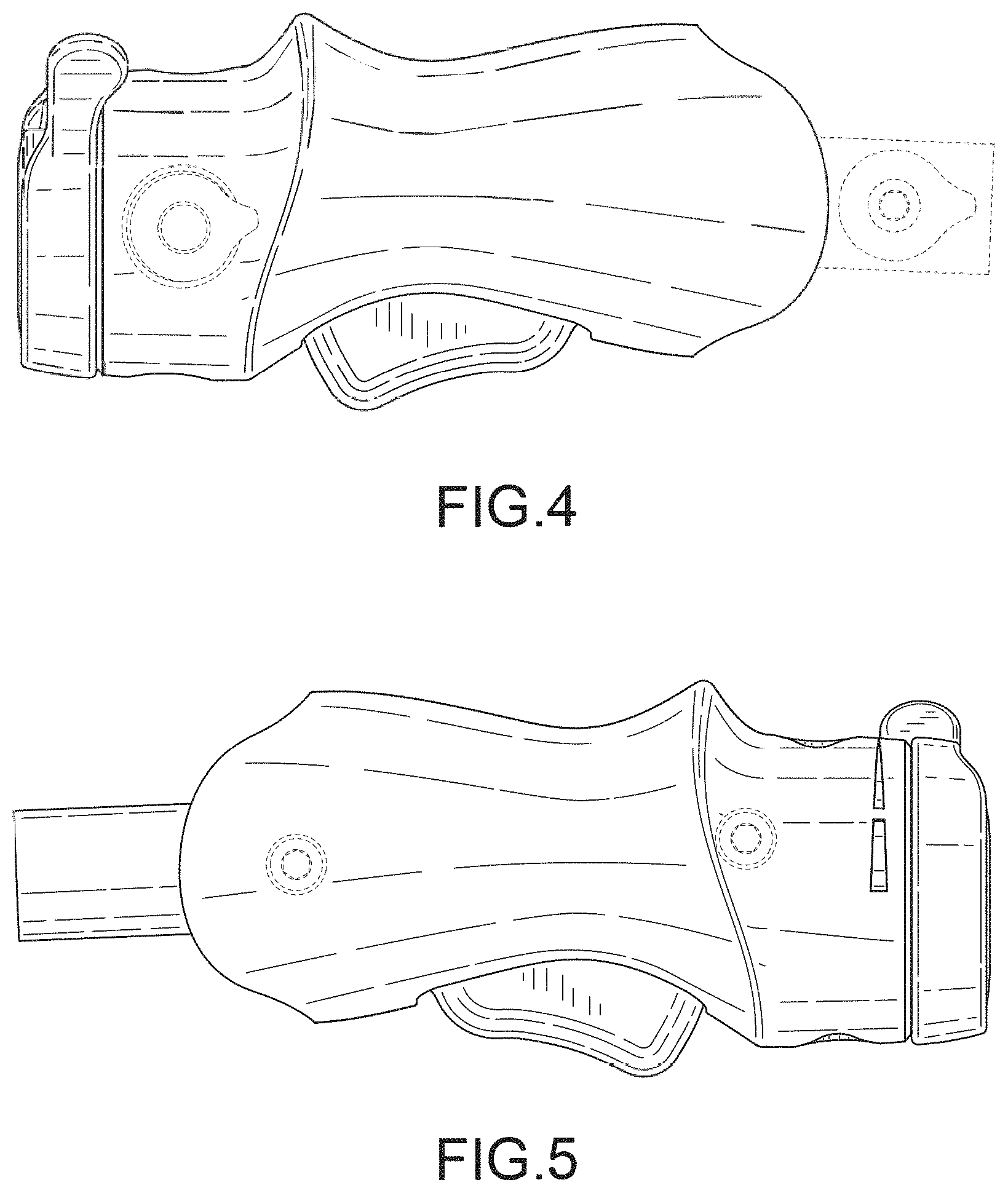
FIG. 4 is a right side view of the camera accessory mount of FIG. 1.
FIG. 5 is a left side view of the camera accessory mount of FIG. 1.
FIG. 6 is a top view of the camera accessory mount of FIG. 1; and,
FIG. 7 is a bottom view of the camera accessory mount of FIG. 1.
The dashed lines depict portions of the camera accessory mount that form no part of the claimed design.
* * * * *
References
D00000
D00001
D00002
D00003
D00004
D00005
XML
uspto.report is an independent third-party trademark research tool that is not affiliated, endorsed, or sponsored by the United States Patent and Trademark Office (USPTO) or any other governmental organization. The information provided by uspto.report is based on publicly available data at the time of writing and is intended for informational purposes only.
While we strive to provide accurate and up-to-date information, we do not guarantee the accuracy, completeness, reliability, or suitability of the information displayed on this site. The use of this site is at your own risk. Any reliance you place on such information is therefore strictly at your own risk.
All official trademark data, including owner information, should be verified by visiting the official USPTO website at www.uspto.gov. This site is not intended to replace professional legal advice and should not be used as a substitute for consulting with a legal professional who is knowledgeable about trademark law.