Radial bearing
Kolste , et al.
U.S. patent number D888,788 [Application Number D/606,797] was granted by the patent office on 2020-06-30 for radial bearing. This patent grant is currently assigned to US SYNTHETIC CORPORATION. The grantee listed for this patent is US SYNTHETIC CORPORATION. Invention is credited to Jair J. Gonzalez, Tyler Kolste, Trond Pedersen, S. Barrett Peterson.


View All Diagrams
| United States Patent | D888,788 |
| Kolste , et al. | June 30, 2020 |
Radial bearing
Claims
CLAIM The ornamental design for a radial bearing, as shown and described.
| Inventors: | Kolste; Tyler (American Fork, UT), Peterson; S. Barrett (Orem, UT), Gonzalez; Jair J. (Provo, UT), Pedersen; Trond (Bluffdale, UT) | ||||||||||
|---|---|---|---|---|---|---|---|---|---|---|---|
| Applicant: |
|
||||||||||
| Assignee: | US SYNTHETIC CORPORATION (Orem,
UT) |
||||||||||
| Appl. No.: | D/606,797 | ||||||||||
| Filed: | June 7, 2017 |
| Current U.S. Class: | D15/143 |
| Current International Class: | 1503 |
| Field of Search: | ;D15/5,138,143 ;D12/400,159,161,206 ;D8/358,359,356 ;D14/484 ;D3/24 |
References Cited [Referenced By]
U.S. Patent Documents
| D28869 | June 1898 | Perkins |
| D258828 | April 1981 | Zrobek |
| D436117 | January 2001 | Chuang |
| D443627 | June 2001 | West |
| D444802 | July 2001 | Dyson |
| 6338754 | January 2002 | Cannon et al. |
| 7866418 | January 2011 | Bertagnolli et al. |
| 8236074 | August 2012 | Bertagnolli et al. |
| 8545104 | October 2013 | Sexton et al. |
| D699272 | February 2014 | Mochizuki |
| 8668388 | March 2014 | Peterson |
| 8746979 | June 2014 | Cooley et al. |
| 8995742 | March 2015 | Mukhopadhyay et al. |
| 9016405 | April 2015 | Sexton et al. |
| 9062505 | June 2015 | Crockett et al. |
| 9062710 | June 2015 | Lee |
| 9315881 | April 2016 | Linford et al. |
| 9459236 | October 2016 | Bertagnolli et al. |
| D770547 | November 2016 | Yamamoto |
| D772964 | November 2016 | Ban |
| D782180 | March 2017 | Eberhard |
| 9664231 | May 2017 | Omoto |
| 9677617 | June 2017 | Karlsson |
| D818508 | May 2018 | Ban |
| D824967 | August 2018 | Getto |
| D830435 | October 2018 | Wakisaka |
| D861756 | October 2019 | Pop |
| 2003/0026718 | February 2003 | Dziver |
| 2008/0112658 | May 2008 | Justin |
| 2009/0260895 | October 2009 | Vail et al. |
| 2010/0166347 | July 2010 | Wendling |
| 2012/0057814 | March 2012 | Dadson et al. |
| 2012/0241226 | September 2012 | Bertagnolli et al. |
| 2014/0366456 | December 2014 | Chapman et al. |
| 2014/0367176 | December 2014 | Gonzalez et al. |
Other References
|
US. Appl. No. 29/606,740, filed Jun. 7, 2017. cited by applicant . U.S. Appl. No. 62/279,271, filed Jan. 15, 2016. cited by applicant . U.S. Appl. No. 62/516,226, filed Jun. 7, 2017. cited by applicant . International Search Report and Written Opinion form International Application No. PCT.US2018/03190 dated Jul. 19, 2018. cited by applicant . Notice of Allowance for U.S. Appl. No. 29/606,740 dated Feb. 19, 2020. cited by applicant. |
Primary Examiner: Anwar; Khawaja
Attorney, Agent or Firm: Dorsey & Whitney LLP
Description
FIG. 1 is a perspective view of a radial bearing including a bearing element having a plurality of grooves in a bearing surface thereof, according to a first embodiment;
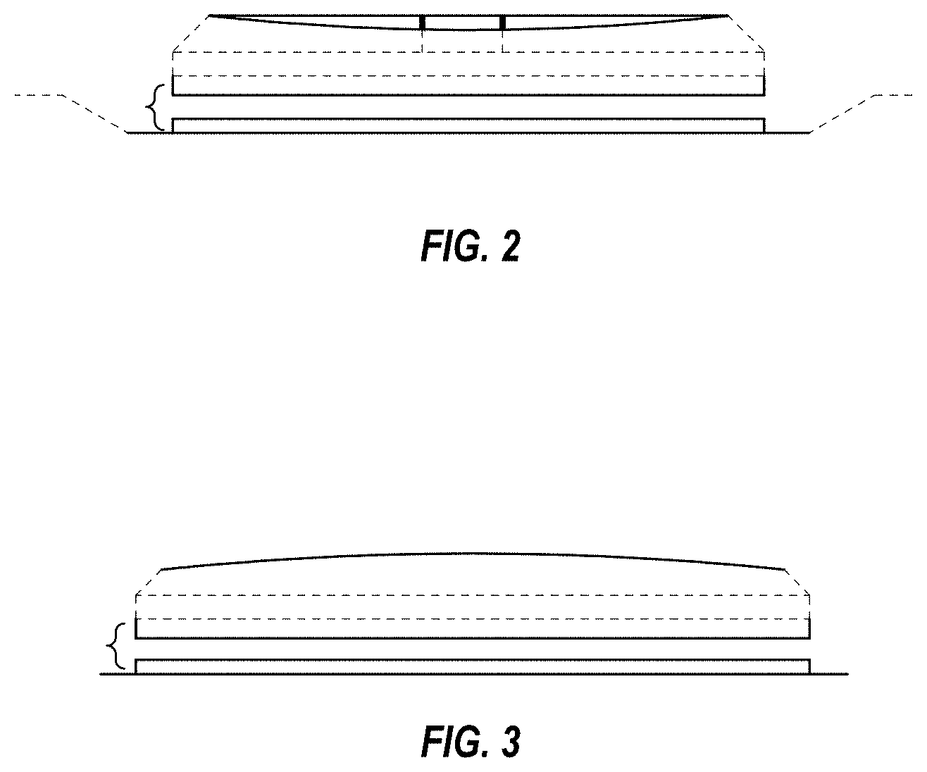
FIG. 2 is a side elevational view of the bearing element shown in FIG. 1, with the opposing side elevational view being identical;
FIG. 3 is a side elevational view of the bearing element shown in FIG. 1 and rotated 90.degree. relative to the side elevational view shown in FIG. 2, with the opposing side elevational view being identical;
FIG. 4 is a perspective view of a radial bearing including a plurality of bearing elements that each have a plurality of grooves in a bearing surface thereof, according to a second embodiment;
FIG. 5 is a side elevational view of one of the bearing elements shown in FIG. 4, with the opposing side elevational view being identical;
FIG. 6 is a side elevational view of one of the bearing elements shown in FIG. 4 and rotated 90.degree. relative to the side elevational view shown in FIG. 5, with the opposing side elevational view being identical;
FIG. 7 is a perspective view of a radial bearing including a plurality of bearing elements that each have a plurality of grooves in a bearing surface thereof, according to a third embodiment;
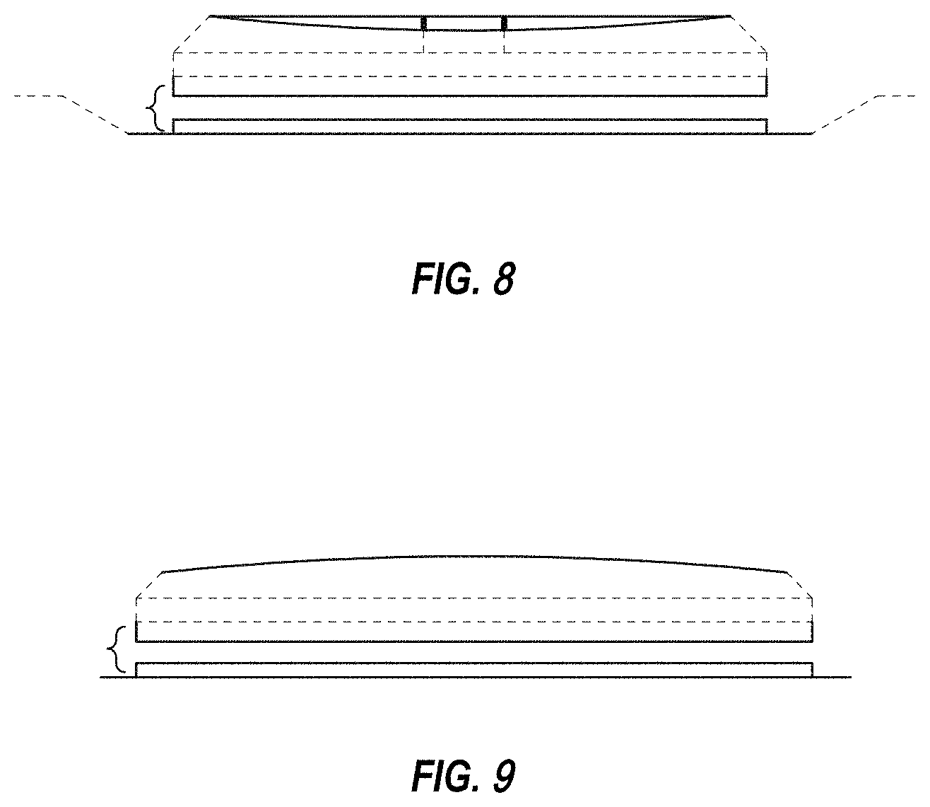
FIG. 8 is a side elevational view of one of the bearing elements shown in FIG. 7, with the opposing side elevational view being identical;
FIG. 9 is a side elevational view of one of the bearing elements shown in FIG. 7 and rotated 90.degree. relative to the side elevational view shown in FIG. 8, with the opposing side elevational view being identical;
FIG. 10 is a perspective view of a radial bearing including a plurality of bearing elements that each have a plurality of grooves in a bearing surface thereof, according to a fourth embodiment;
FIG. 11 is a side elevational view of one of the bearing elements shown in FIG. 10, with the opposing side elevational view being identical;
FIG. 12 is a side elevational view of one of the bearing elements shown in FIG. 10 and rotated 90.degree. relative to the side elevational view shown in FIG. 11, with the opposing side elevational view being identical;
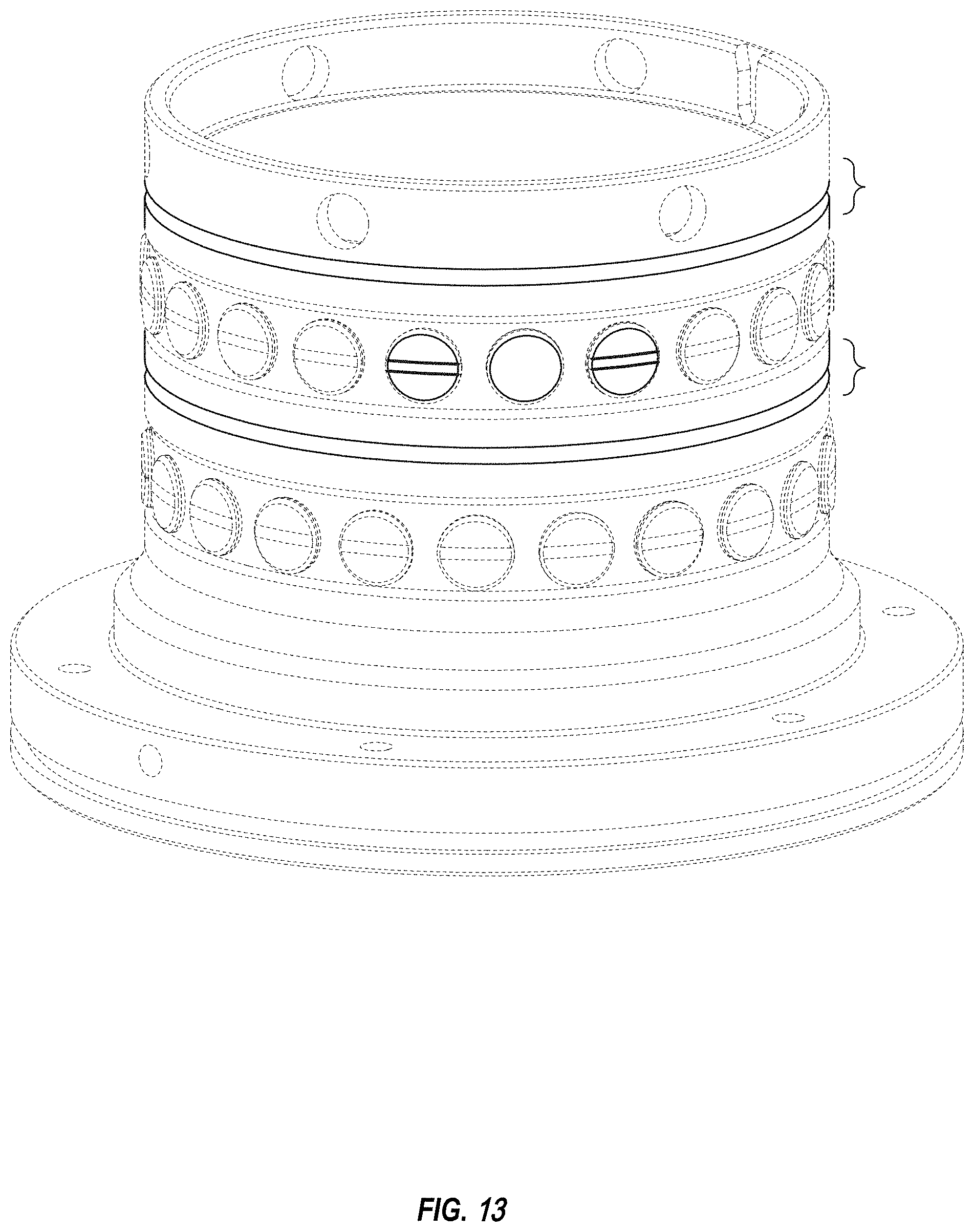
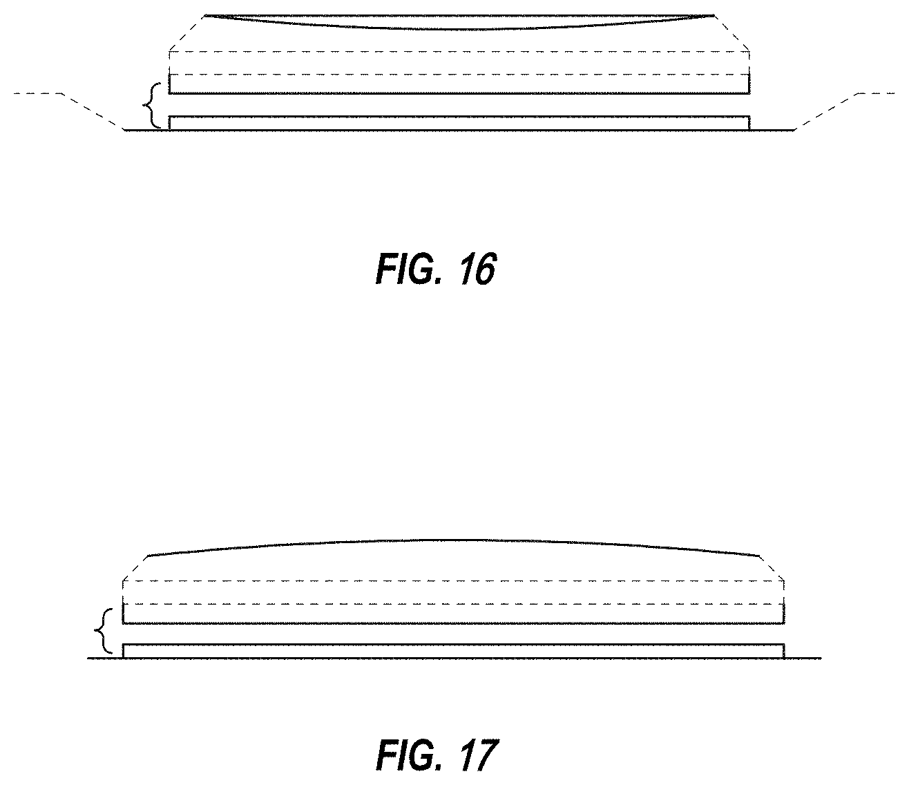
FIG. 13 is a perspective view of a radial bearing including a plurality of first bearing elements that each have a plurality of grooves in a bearing surface thereof and a second bearing element that does not include any grooves in a bearing surface thereof, according to a fifth embodiment;
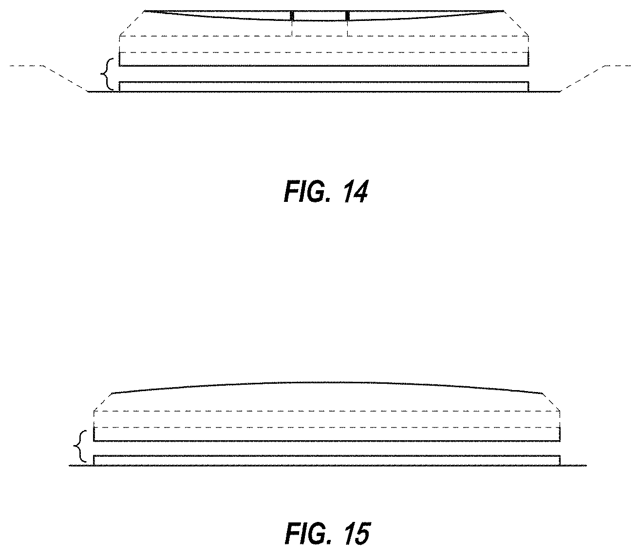
FIG. 14 is a side elevational view of one of the first bearing elements shown in FIG. 13, with the opposing side elevational view being identical;
FIG. 15 is a side elevational view of one of the first bearing elements shown in FIG. 13 and rotated 90.degree. relative to the side elevational view shown in FIG. 14, with the opposing side elevational view being identical;
FIG. 16 is a side elevational view of the second bearing element shown in FIG. 13, with the opposing side elevational view being identical;
FIG. 17 is a side elevational view of the second bearing element shown in FIG. 13 and rotated 90.degree. relative to the side elevational view shown in FIG. 16, with the opposing side elevational view being identical;
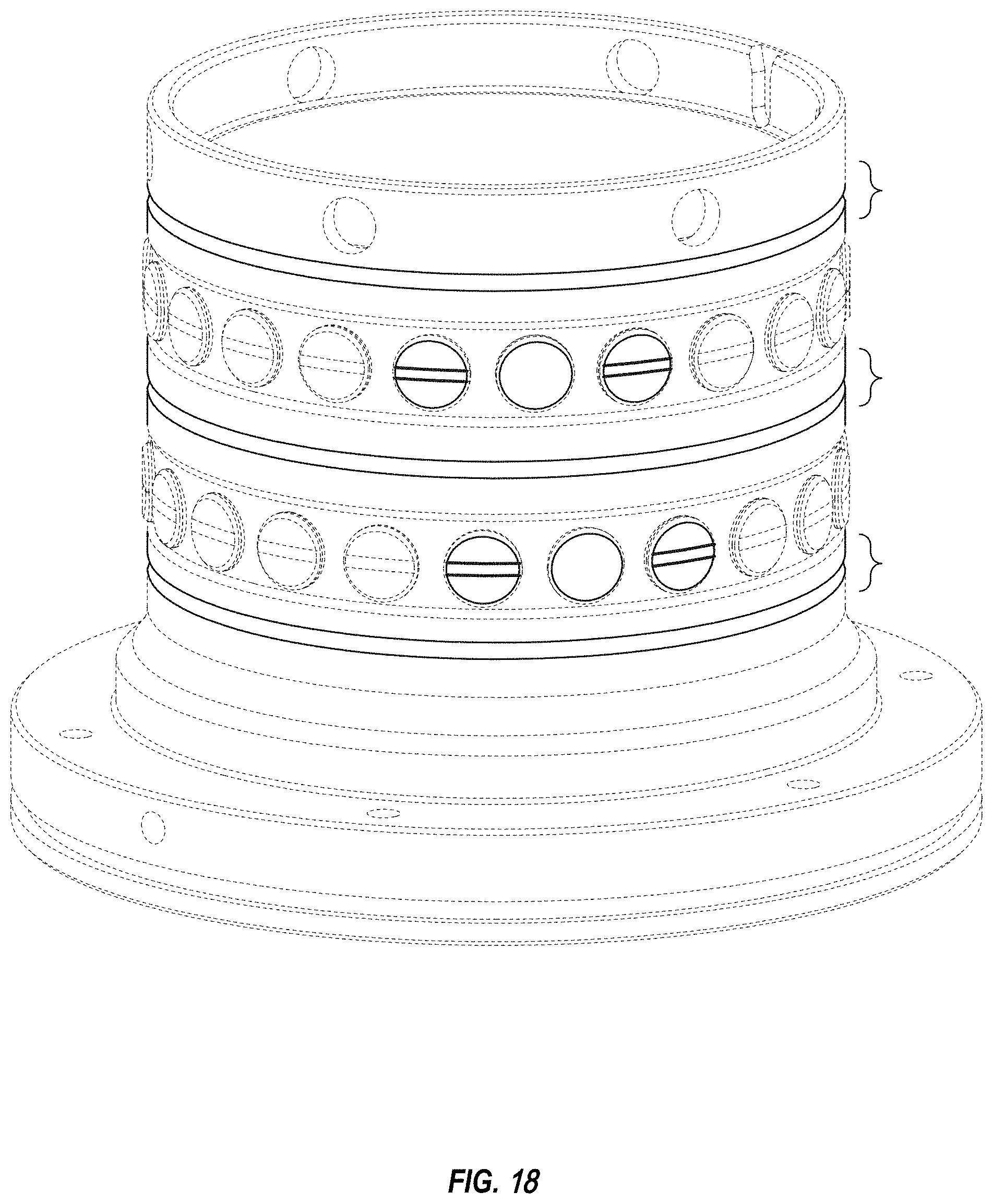
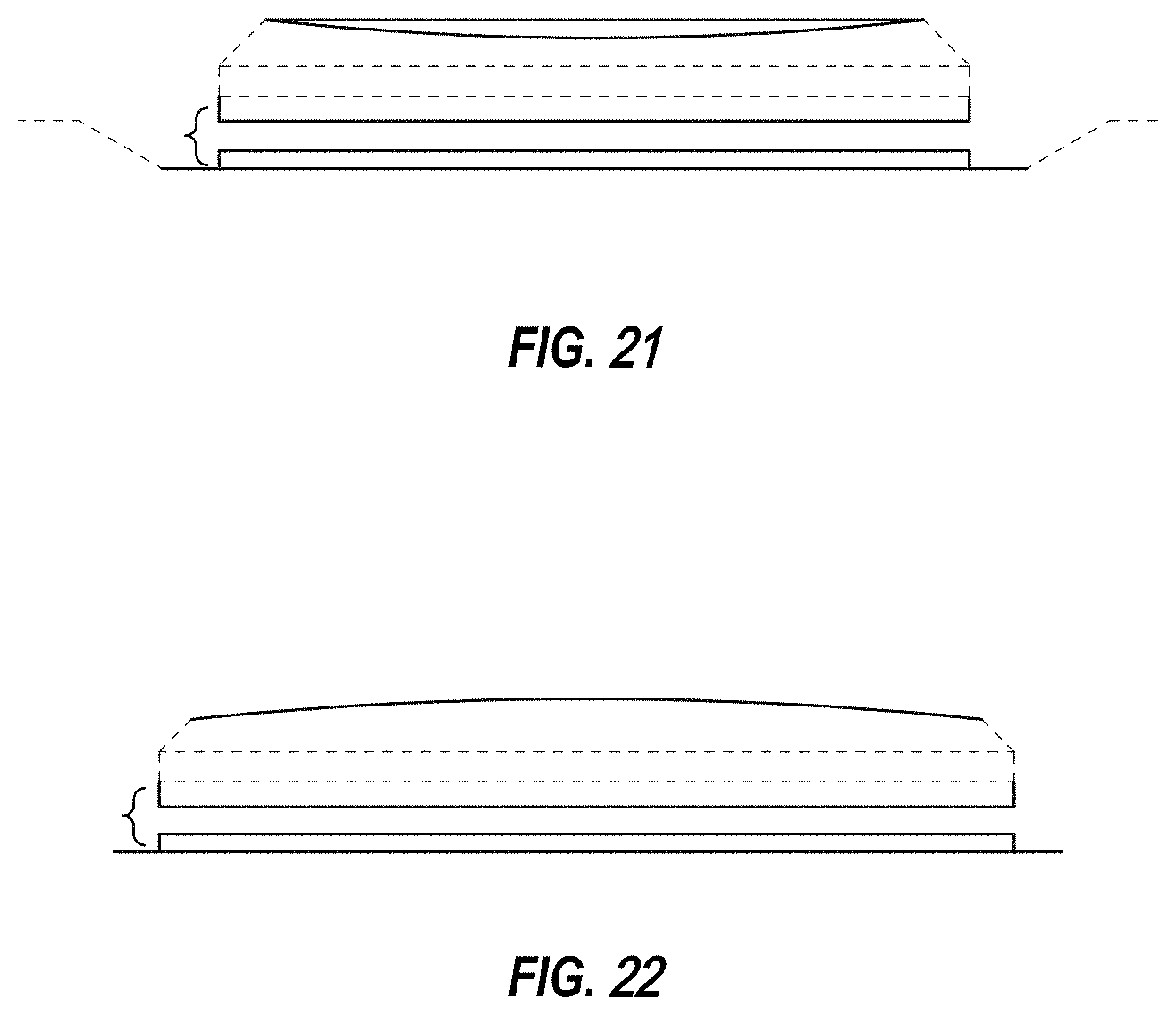
FIG. 18 is a perspective view of a radial bearing including a plurality of first bearing elements that each have a plurality of grooves in a bearing surface thereof and a plurality of second bearing elements that do not include any grooves in a bearing surface thereof, according to an sixth embodiment;
FIG. 19 is a side elevational view of one of the first bearing elements shown in FIG. 18, with the opposing side elevational view being identical;
FIG. 20 is a side elevational view of one of the first bearing elements shown in FIG. 18 and rotated 90.degree. relative to the side elevational view shown in FIG. 19, with the opposing side elevational view being identical;
FIG. 21 is a side elevational view of one of the second bearing elements shown in FIG. 18, with the opposing side elevational view being identical;
FIG. 22 is a side elevational view of one of the second bearing elements shown in FIG. 18 and rotated 90.degree. relative to the side elevational view shown in FIG. 21, with the opposing side elevational view being identical;
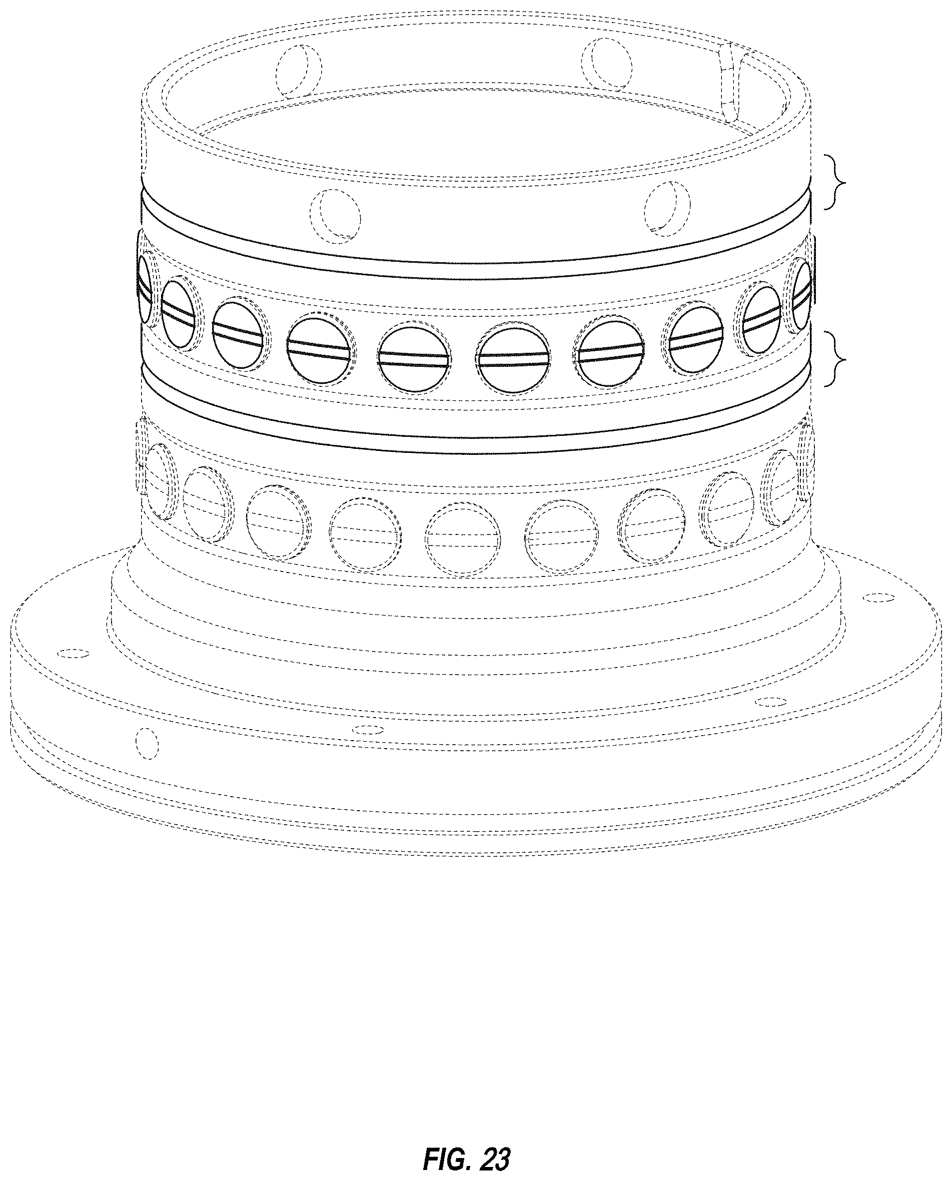
FIG. 23 is a perspective view of a radial bearing including a plurality of bearing elements that each have a plurality of grooves in a bearing surface thereof, according to a seventh embodiment;
FIG. 24 is a side elevational view of one of the bearing elements shown in FIG. 23, with the opposing side elevational view being identical;
FIG. 25 is a side elevational view of one of the bearing elements shown in FIG. 23 and rotated 90.degree. relative to the side elevational view shown in FIG. 24, with the opposing side elevational view being identical;
FIG. 26 is a perspective view of a radial bearing including a plurality of bearing elements that each have a plurality of grooves in a bearing surface thereof, according to a
FIG. 27 is a side elevational view of one of the bearing elements shown in FIG. 26, with the opposing side elevational view being identical; and,
FIG. 28 is a side elevational view of one of the bearing elements shown in FIG. 26 and rotated 90.degree. relative to the side elevational view shown in FIG. 27, with the opposing side elevational view being identical.
The broken lines shown in the drawings are for illustrative purposes only and form no part of the claimed design.
* * * * *
D00000
D00001
D00002
D00003
D00004
D00005
D00006
D00007
D00008
D00009
D00010
D00011
D00012
D00013

D00014
D00015
D00016

D00017

D00018

XML
uspto.report is an independent third-party trademark research tool that is not affiliated, endorsed, or sponsored by the United States Patent and Trademark Office (USPTO) or any other governmental organization. The information provided by uspto.report is based on publicly available data at the time of writing and is intended for informational purposes only.
While we strive to provide accurate and up-to-date information, we do not guarantee the accuracy, completeness, reliability, or suitability of the information displayed on this site. The use of this site is at your own risk. Any reliance you place on such information is therefore strictly at your own risk.
All official trademark data, including owner information, should be verified by visiting the official USPTO website at www.uspto.gov. This site is not intended to replace professional legal advice and should not be used as a substitute for consulting with a legal professional who is knowledgeable about trademark law.