Analytical instrument
Stone , et al.
U.S. patent number D887,296 [Application Number D/681,398] was granted by the patent office on 2020-06-16 for analytical instrument. This patent grant is currently assigned to BERKELEY LIGHTS, INC.. The grantee listed for this patent is BERKELEY LIGHTS, INC.. Invention is credited to Keith J. Breinlinger, Bryan R. Hotaling, Edward J. Milovic, James M. Ormond, Christopher C. Shing, Michael J. Stone, James R. Varney, Matthew C. White.


| United States Patent | D887,296 |
| Stone , et al. | June 16, 2020 |
Analytical instrument
Claims
CLAIM The ornamental design for an analytical instrument, as shown and described.
| Inventors: | Stone; Michael J. (Berkeley, CA), Breinlinger; Keith J. (San Rafael, CA), Milovic; Edward J. (Albany, CA), Shing; Christopher C. (Castro Valley, CA), Varney; James R. (Bolton, MA), Ormond; James M. (Belmont, MA), White; Matthew C. (Brighton, MA), Hotaling; Bryan R. (Harvard, MA) | ||||||||||
|---|---|---|---|---|---|---|---|---|---|---|---|
| Applicant: |
|
||||||||||
| Assignee: | BERKELEY LIGHTS, INC.
(Emeryville, CA) |
||||||||||
| Appl. No.: | D/681,398 | ||||||||||
| Filed: | February 25, 2019 |
Related U.S. Patent Documents
| Application Number | Filing Date | Patent Number | Issue Date | ||
|---|---|---|---|---|---|
| 29609549 | Jun 30, 2017 | D844471 | |||
| Current U.S. Class: | D10/81; D24/216 |
| Current International Class: | 1004 |
| Field of Search: | ;D10/81 ;D24/216,219,220,232,233,234 |
References Cited [Referenced By]
U.S. Patent Documents
| D672471 | December 2012 | Franco |
| D777049 | January 2017 | Barton |
Attorney, Agent or Firm: McDermott Will & Emery LLP
Description
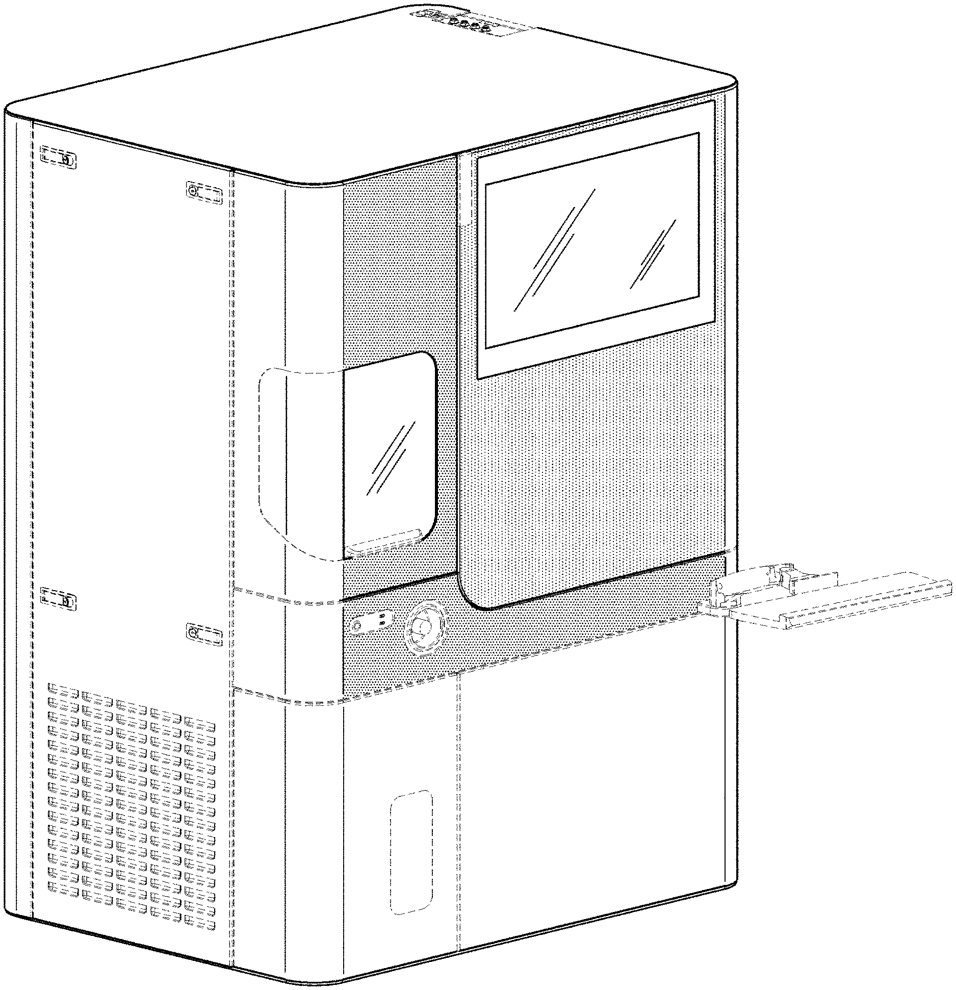
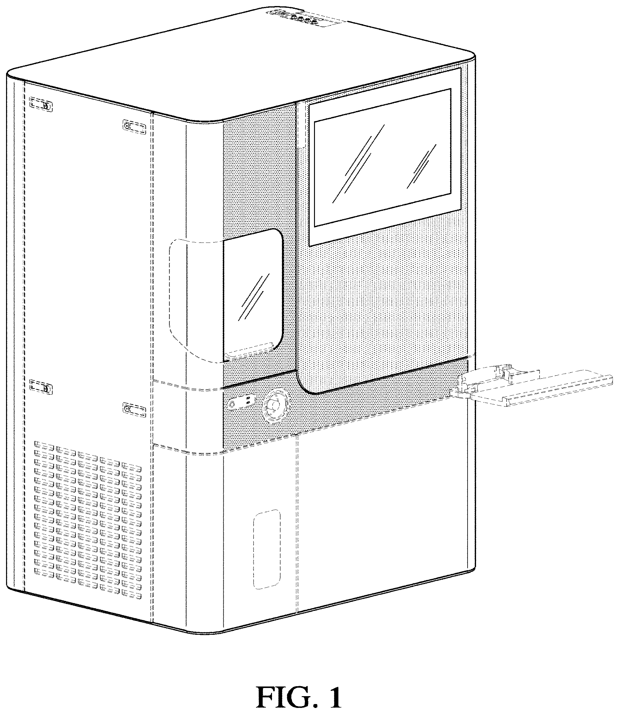
FIG. 1 is a perspective view of an embodiment of an analytical instrument of our new design.
FIG. 2 is a front view of the embodiment of an analytical instrument of our new design.
FIG. 3 is a back view of the embodiment of an analytical instrument of our new design.
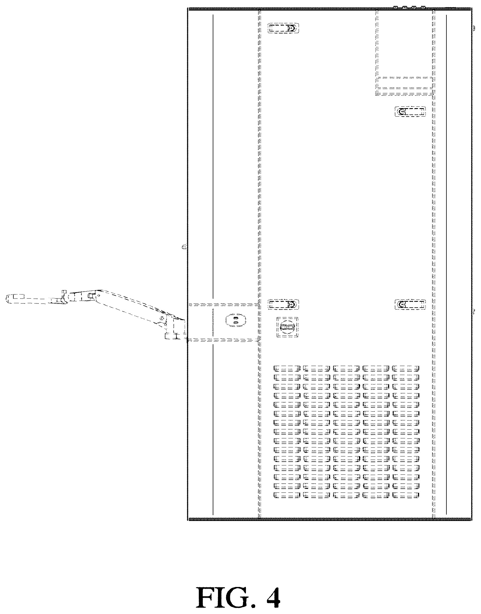
FIG. 4 is a side view of the embodiment of an analytical instrument of our new design.
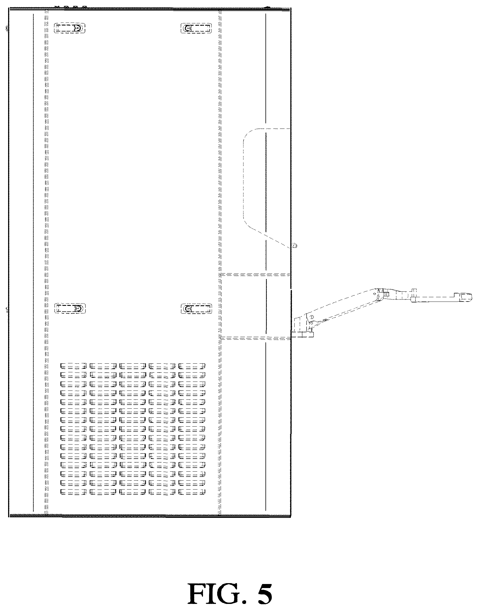
FIG. 5 is a side view of the embodiment of an analytical instrument of our new design.
FIG. 6 is a top view of the embodiment of an analytical instrument of our new design; and,
FIG. 7 is a bottom view of the embodiment of an analytical instrument of our new design.
The portions of the features depicted in broken lines are not part of the claimed design.
* * * * *
D00000
D00001
D00002
D00003
D00004
D00005
D00006
D00007
XML
uspto.report is an independent third-party trademark research tool that is not affiliated, endorsed, or sponsored by the United States Patent and Trademark Office (USPTO) or any other governmental organization. The information provided by uspto.report is based on publicly available data at the time of writing and is intended for informational purposes only.
While we strive to provide accurate and up-to-date information, we do not guarantee the accuracy, completeness, reliability, or suitability of the information displayed on this site. The use of this site is at your own risk. Any reliance you place on such information is therefore strictly at your own risk.
All official trademark data, including owner information, should be verified by visiting the official USPTO website at www.uspto.gov. This site is not intended to replace professional legal advice and should not be used as a substitute for consulting with a legal professional who is knowledgeable about trademark law.