Tube coupling
Lundkvist , et al.
U.S. patent number D886,994 [Application Number D/630,285] was granted by the patent office on 2020-06-09 for tube coupling. This patent grant is currently assigned to GE HEALTHCARE BIO-SCIENCES AB. The grantee listed for this patent is GE HEALTHCARE BIO-SCIENCES AB. Invention is credited to Tim Francois, Bjorn A. Johansson, Mats Lundkvist.

| United States Patent | D886,994 |
| Lundkvist , et al. | June 9, 2020 |
Tube coupling
Claims
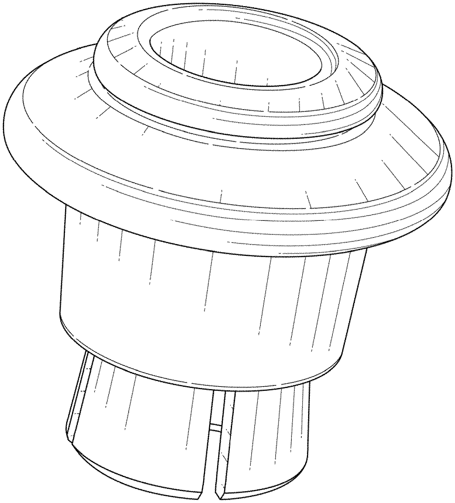
CLAIM We claim the ornamental design for a tube coupling, as shown and described.
| Inventors: | Lundkvist; Mats (Uppsala, SE), Johansson; Bjorn A. (Uppsala, SE), Francois; Tim (Uppsala, SE) | ||||||||||
|---|---|---|---|---|---|---|---|---|---|---|---|
| Applicant: |
|
||||||||||
| Assignee: | GE HEALTHCARE BIO-SCIENCES AB
(Uppsala, SE) |
||||||||||
| Appl. No.: | D/630,285 | ||||||||||
| Filed: | December 20, 2017 |
Foreign Application Priority Data
| Jun 27, 2017 [GB] | 6014450 | |||
| Current U.S. Class: | D24/129; D23/262 |
| Current International Class: | 2404 |
| Field of Search: | ;D23/259,262,263,265-266 ;D8/382,386 ;285/15-16,31,33,45,53,86,104,125.1,179,180,285.1,294.1,294.3,373,417,3,39,105,113,257,305,321,323,340,423 ;251/146-152 ;138/99 ;D24/127,129,110.6,110.12 |
References Cited [Referenced By]
U.S. Patent Documents
| 3243206 | March 1966 | Samer |
| 3649050 | March 1972 | Woodling |
| D232519 | August 1974 | Saisho |
| 4541658 | September 1985 | Bartholomew |
| D293883 | January 1988 | Hirohata |
| 4951391 | August 1990 | Seabra |
| 5909902 | June 1999 | Seabra |
| 6568714 | May 2003 | Stripe |
| 7690693 | April 2010 | Moner |
| 9261214 | February 2016 | Guest |
| 10221979 | March 2019 | Owen |
| 2004/0108712 | June 2004 | Liang |
| 2011/0309614 | December 2011 | Guest |
| 2012/0306197 | December 2012 | Liu |
Other References
|
Design U.S. AppL. No. 29/630,293, filed Dec. 20, 2017. cited by applicant. |
Primary Examiner: Wierenga; Amy C
Attorney, Agent or Firm: Eversheds Sutherland (US) LLP
Description
FIG. 1 is a right side upper perspective view in a released position showing our new design of the tube coupling;
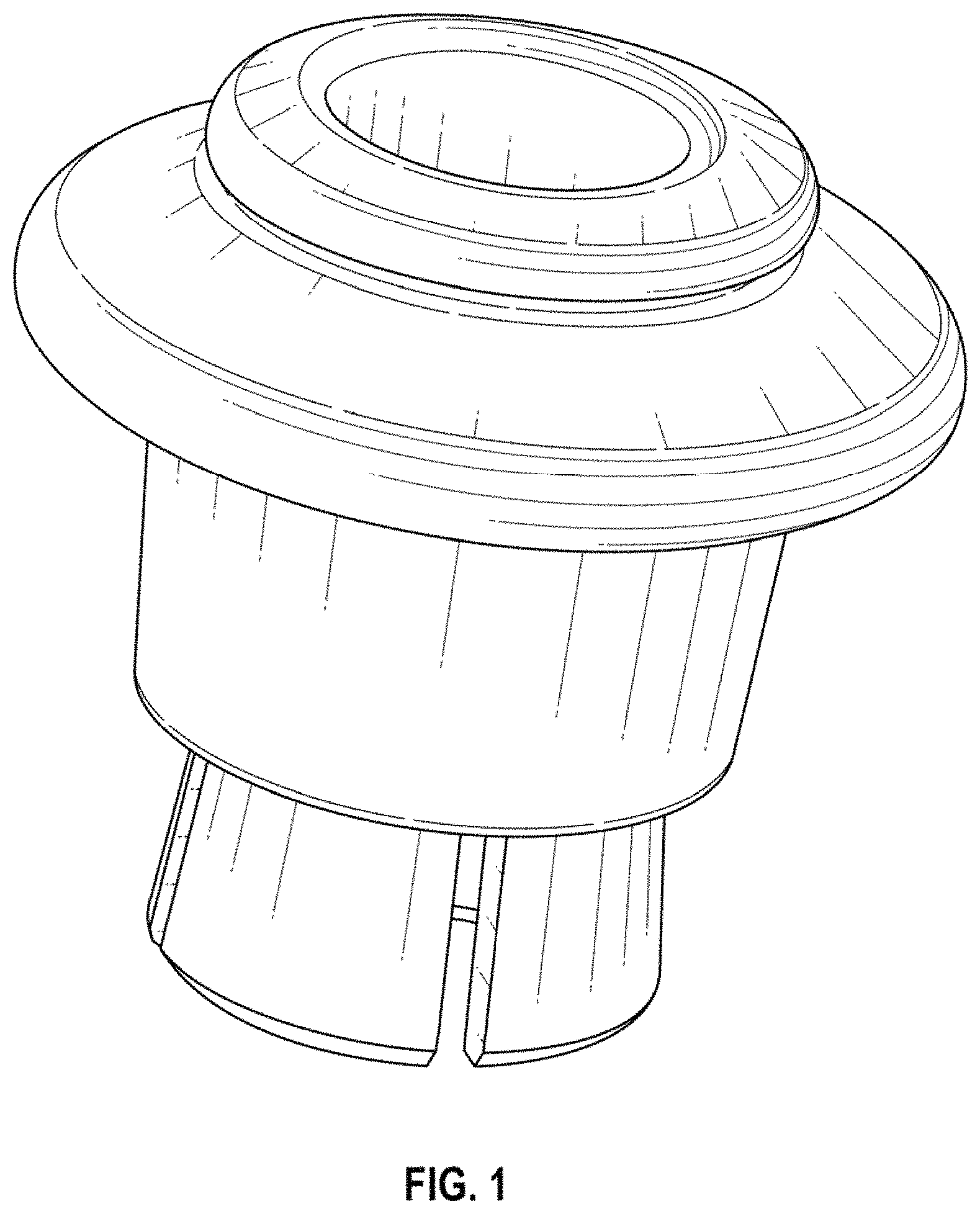
FIG. 2 is a right side upper perspective view in a clamped position showing our new design of the tube coupling;
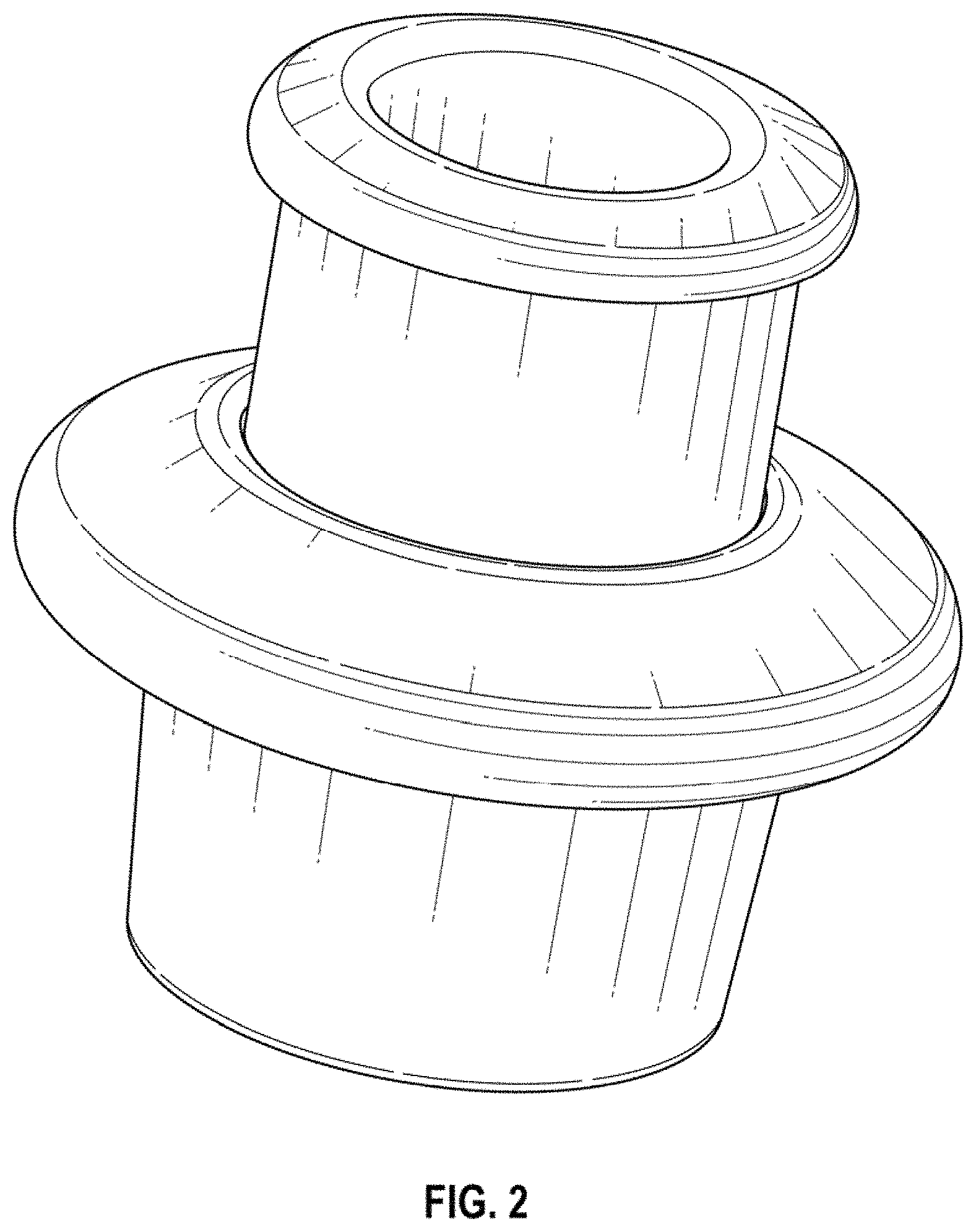
FIG. 3 is a left side lower perspective view in a released position showing our new design of the releasable tube coupling;
FIG. 4 is a right side elevation view in a clamped position showing our new design of the tube coupling; and,
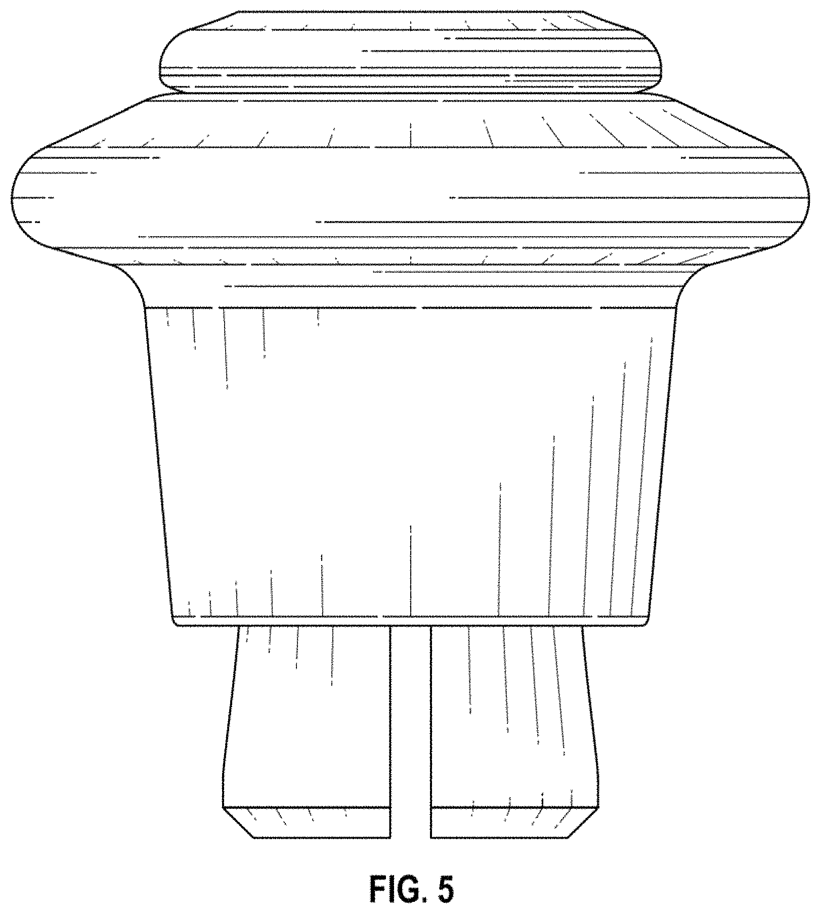
FIG. 5 is a right side elevation view in a released position showing our new design of the tube coupling.
* * * * *
D00000
D00001
D00002
D00003
D00004
D00005
XML
uspto.report is an independent third-party trademark research tool that is not affiliated, endorsed, or sponsored by the United States Patent and Trademark Office (USPTO) or any other governmental organization. The information provided by uspto.report is based on publicly available data at the time of writing and is intended for informational purposes only.
While we strive to provide accurate and up-to-date information, we do not guarantee the accuracy, completeness, reliability, or suitability of the information displayed on this site. The use of this site is at your own risk. Any reliance you place on such information is therefore strictly at your own risk.
All official trademark data, including owner information, should be verified by visiting the official USPTO website at www.uspto.gov. This site is not intended to replace professional legal advice and should not be used as a substitute for consulting with a legal professional who is knowledgeable about trademark law.