Ankle brace
Schiaparelli , et al.
U.S. patent number D885,594 [Application Number D/681,465] was granted by the patent office on 2020-05-26 for ankle brace. This patent grant is currently assigned to AVATION MEDICAL, INC.. The grantee listed for this patent is VERESSA MEDICAL, INC.. Invention is credited to Francis Paul Harrington, Alireza Mashal, Anna Christina Miller, Serge Roux, Jill F. Schiaparelli, Joyce Chien Tu, Benjamin Zwillinger.


| United States Patent | D885,594 |
| Schiaparelli , et al. | May 26, 2020 |
Ankle brace
Claims
CLAIM We claim the ornamental design for an ankle brace, as shown and described.
| Inventors: | Schiaparelli; Jill F. (Mason, OH), Harrington; Francis Paul (Peabody, MA), Roux; Serge (Boston, MA), Zwillinger; Benjamin (Seattle, WA), Miller; Anna Christina (Anchorage, AK), Mashal; Alireza (Middleton, WI), Tu; Joyce Chien (Arlington, MA) | ||||||||||
|---|---|---|---|---|---|---|---|---|---|---|---|
| Applicant: |
|
||||||||||
| Assignee: | AVATION MEDICAL, INC.
(Columbus, OH) |
||||||||||
| Appl. No.: | D/681,465 | ||||||||||
| Filed: | February 26, 2019 |
| Current U.S. Class: | D24/192 |
| Current International Class: | 2401 |
| Field of Search: | ;D24/190,192 ;D2/970,980,984-986,989 ;D29/120.1,121.2 |
References Cited [Referenced By]
U.S. Patent Documents
| D455213 | April 2002 | Weaver, II |
| D462772 | September 2002 | Lamping |
| 6755800 | June 2004 | Weaver, II |
| D546107 | July 2007 | Babcock |
| D703336 | April 2014 | Eldridge |
| D743557 | November 2015 | Pichette |
| D747560 | January 2016 | Daniels |
| D799709 | October 2017 | Cox |
| D819822 | June 2018 | Schmitt |
| D834205 | November 2018 | Ducharme |
| D834207 | November 2018 | Ducharme |
| D837987 | January 2019 | Ducharme |
| D839439 | January 2019 | Ducharme |
| D844156 | March 2019 | Voskuilen |
| D855815 | August 2019 | Rokitta |
| D859670 | September 2019 | Rokitta |
| 2014/0188024 | July 2014 | Cox |
Attorney, Agent or Firm: Tarolli, Sundheim, Covell & Tummino LLP
Description
FIG. 1 is a top perspective view of one embodiment of an ankle brace comprising a new, original and ornamental design, in a first example use configuration;
FIG. 2 is a top view of a surface of the ankle brace shown in FIG. 1, flattened and viewed looking away from what would be the wearer's body centerline, out of the first example use configuration;
FIG. 3 is a top view of a surface of the ankle brace shown in FIG. 1, flattened and viewed looking away from what would be the wearer's body centerline, out of the first example use configuration;
FIG. 4 is a side view of the ankle brace shown in FIG. 1, taken along the plane of the page from bottom-toward-top in the orientation of FIG. 2, out of the first example use configuration;
FIG. 5 is a side view of the ankle brace shown in FIG. 1, taken along the plane of the page from bottom-toward-top in the orientation of FIG. 3, out of the first example use configuration;
FIG. 6 is a side view of the ankle brace shown in FIG. 1, taken along the plane of the page from left-toward-right in the orientation of FIG. 2, out of the first example use configuration;
FIG. 7 is a side view of the ankle brace shown in FIG. 1, taken along the plane of the page from right-toward-left in the orientation of FIG. 2, out of the first example use configuration;
FIG. 8 is a side view of the ankle brace shown in FIG. 1, in the first example use configuration and viewed looking away from a wearer's body centerline;
FIG. 9 is a side view of the ankle brace shown in FIG. 1, in the first example use configuration and viewed looking toward the wearer's body centerline;
FIG. 10 is a front view of the ankle brace shown in FIG. 1, in the first example use configuration;
FIG. 11 is a rear view of the ankle brace shown in FIG. 1, in the first example use configuration;
FIG. 12 is a top view of the ankle brace shown in FIG. 1, in the first example use configuration;
FIG. 13 is a bottom view of the ankle brace shown in FIG. 1, in the first example use configuration;
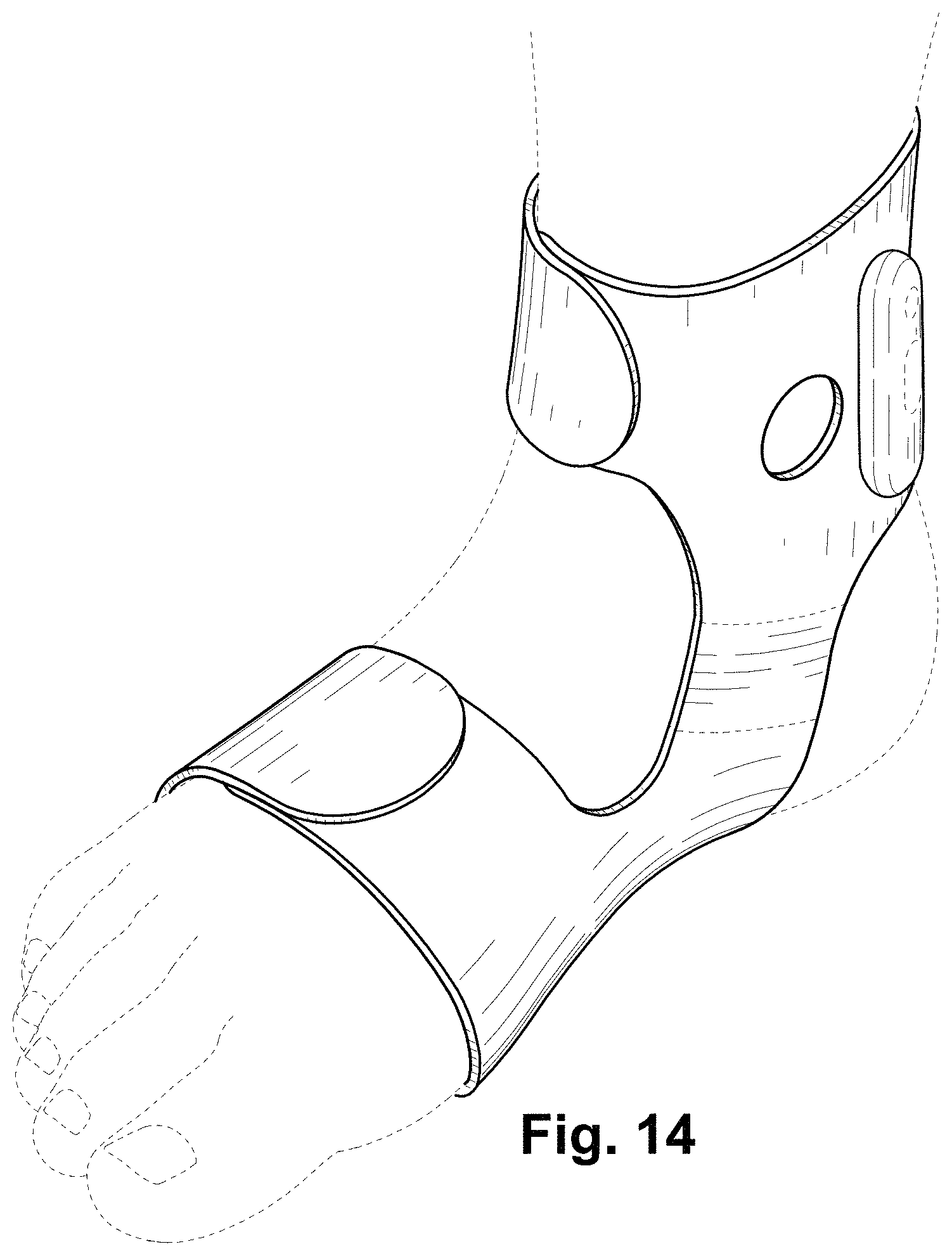
FIG. 14 is a top perspective view of another embodiment of an ankle brace comprising a new, original and ornamental design, in the first example use configuration;
FIG. 15 is a top view of an inward-facing (when in use) surface of the ankle brace shown in FIG. 14, out of the first example use configuration;
FIG. 16 is a top view of an outward-facing (when in use) surface of the ankle brace shown in FIG. 14, out of the first example use configuration;
FIG. 17 is a side view of the ankle brace shown in FIG. 14, taken along the plane of the page from bottom-toward-top in the orientation of FIG. 15, out of the first example use configuration;
FIG. 18 is a side view of the ankle brace shown in FIG. 14, taken along the plane of the page from bottom-toward-top in the orientation of FIG. 16, out of the first example use configuration;
FIG. 19 is a side view of the ankle brace shown in FIG. 14, taken along the plane of the page from left-toward-right in the orientation of FIG. 15, out of the first example use configuration;
FIG. 20 is a side view of the ankle brace shown in FIG. 14, taken along the plane of the page from right-toward-left in the orientation of FIG. 15, out of the first example use configuration;
FIG. 21 is a side view of the ankle brace shown in FIG. 14, in the first example use configuration and viewed looking away from the wearer's body centerline;
FIG. 22 is a side view of the ankle brace shown in FIG. 14, in the first example use configuration and viewed looking toward the wearer's body centerline;
FIG. 23 is a front view of the ankle brace shown in FIG. 14, in the first example use configuration;
FIG. 24 is a rear view of the ankle brace shown in FIG. 14, in the first example use configuration;
FIG. 25 is a top view of the ankle brace shown in FIG. 14, in the first example use configuration; and,
FIG. 26 is a bottom view of the ankle brace shown in FIG. 14, in the first example use configuration.
The broken lines showing a human foot are for the purpose of depicting environment and form no part of the claim. All other broken lines are for the purpose of depicting portions of the ankle brace and form no part of the claim.
* * * * *
D00000
D00001
D00002
D00003
D00004
D00005
D00006
D00007
D00008
XML
uspto.report is an independent third-party trademark research tool that is not affiliated, endorsed, or sponsored by the United States Patent and Trademark Office (USPTO) or any other governmental organization. The information provided by uspto.report is based on publicly available data at the time of writing and is intended for informational purposes only.
While we strive to provide accurate and up-to-date information, we do not guarantee the accuracy, completeness, reliability, or suitability of the information displayed on this site. The use of this site is at your own risk. Any reliance you place on such information is therefore strictly at your own risk.
All official trademark data, including owner information, should be verified by visiting the official USPTO website at www.uspto.gov. This site is not intended to replace professional legal advice and should not be used as a substitute for consulting with a legal professional who is knowledgeable about trademark law.