Handle
Darnel , et al.
U.S. patent number D884,454 [Application Number D/679,092] was granted by the patent office on 2020-05-19 for handle. This patent grant is currently assigned to Thermo CRS Ltd.. The grantee listed for this patent is Thermo CRS Ltd.. Invention is credited to Gary Darnel, Stephen Wayne Johnson, Michael Paul Riff, Jonathan Wittchen.


| United States Patent | D884,454 |
| Darnel , et al. | May 19, 2020 |
Handle
Claims
CLAIM The ornamental design for a handle, as shown and described.
| Inventors: | Darnel; Gary (Hamilton, CA), Riff; Michael Paul (Burlington, CA), Johnson; Stephen Wayne (Waterdown, CA), Wittchen; Jonathan (Burlington, CA) | ||||||||||
|---|---|---|---|---|---|---|---|---|---|---|---|
| Applicant: |
|
||||||||||
| Assignee: | Thermo CRS Ltd. (Burlington,
CA) |
||||||||||
| Appl. No.: | D/679,092 | ||||||||||
| Filed: | February 1, 2019 |
| Current U.S. Class: | D8/308 |
| Current International Class: | 0806 |
| Field of Search: | ;D8/300-302,307-309 ;D23/250,252 ;D7/393 |
References Cited [Referenced By]
U.S. Patent Documents
| D290578 | June 1987 | Belaiche |
| D299109 | December 1988 | Jans |
| D315858 | April 1991 | Frattini |
| D364217 | November 1995 | Dubin |
| 5813708 | September 1998 | Shen |
| D619872 | July 2010 | Singtoroj |
| D737652 | September 2015 | Harden |
| D738468 | September 2015 | Bahler |
| D745359 | December 2015 | Sun |
| D797541 | September 2017 | Groleski |
| 2004/0134750 | July 2004 | Luoma, II |
| 9826746 | Jun 1998 | WO | |||
Other References
|
Highres Biosolutions, CoLAB Flex Mobile, Modular Lab Automation, www.highresbio.com, 2018 (3 pages). cited by applicant . Canadian Intellectual Property Office, International Search Report and Written Opinion of the International Searching Authority, International Application No. PCT/CA2019/050130, dated Apr. 17, 2019 (11 pages). cited by applicant. |
Primary Examiner: Calve; Lauren R
Attorney, Agent or Firm: Wood Herron & Evans LLP
Description
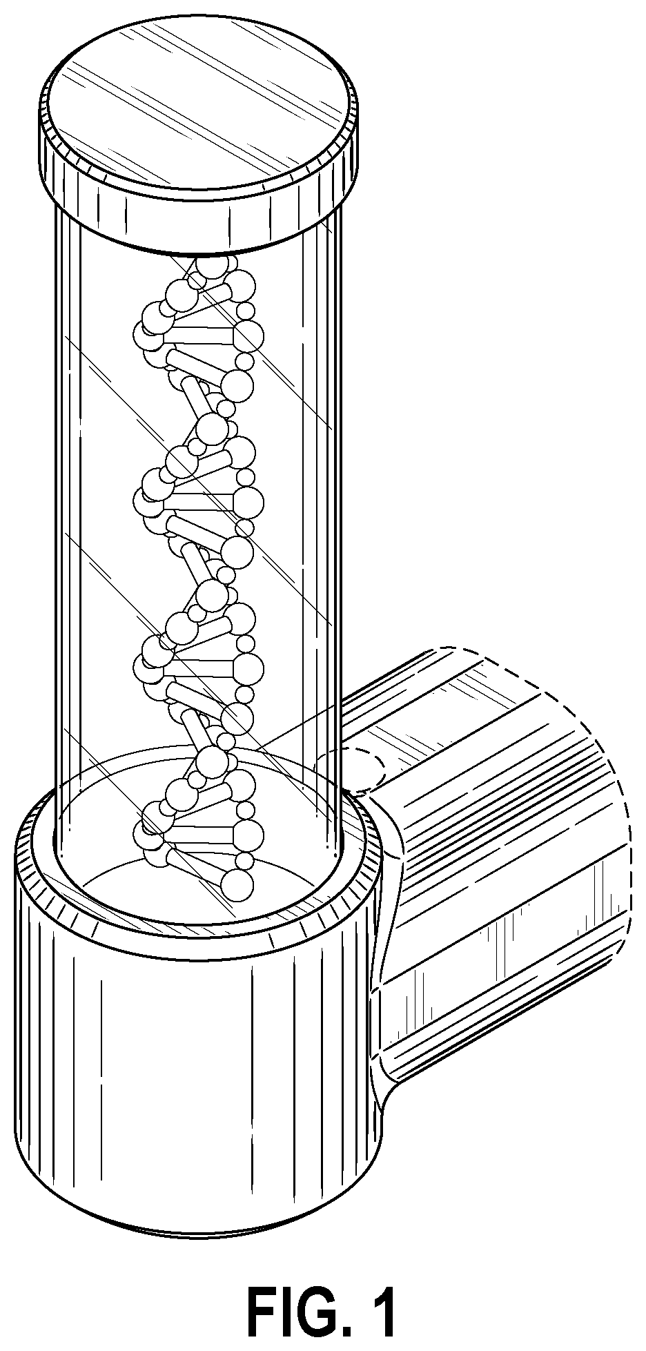
FIG. 1 is an isometric view of a handle showing our new design in a non-illuminated state.
FIG. 2 is a front elevation view thereof.
FIG. 3 rear elevation view thereof.
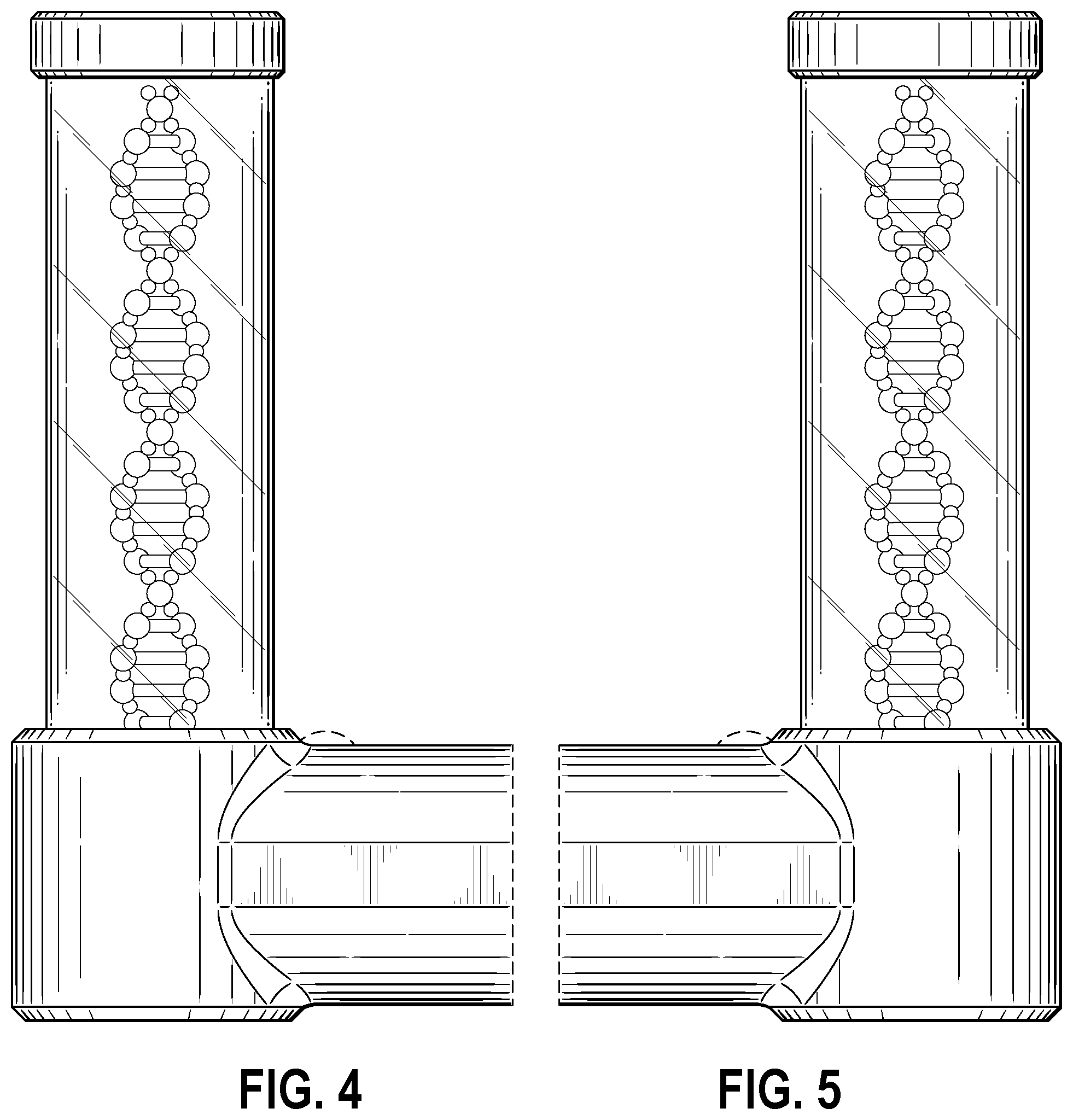
FIG. 4 right side elevation view thereof.
FIG. 5 is a left side elevation view thereof.
FIG. 6 is a top plan view thereof.
FIG. 7 is a bottom plan view thereof.
FIG. 8 is an isometric view a handle showing our new design in an illuminated state.
FIG. 9 is a front elevation view thereof.
FIG. 10 rear elevation view thereof.
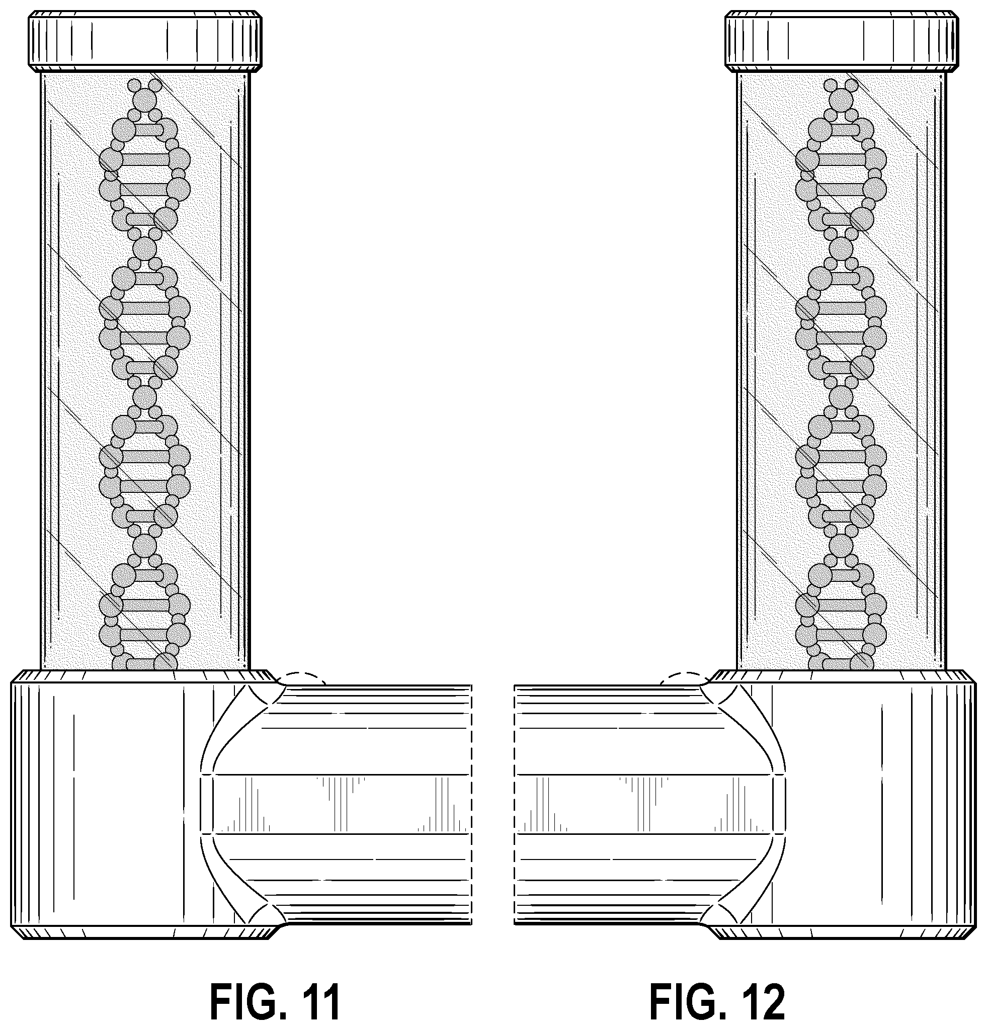
FIG. 11 right side elevation view thereof.
FIG. 12 is a left side elevation view thereof.
FIG. 13 is a top plan view thereof; and,
FIG. 14 is a bottom plan view thereof.
The portions of FIGS. 1-14 shown in broken dash lines form no part of the claimed invention and are for illustrative purposes only. Neither the portions of the invention shown in broken dash line nor the broken dash lines themselves form any part of the claimed invention. The portions of FIGS. 8-12 shown in stippled diffusion dither represent the design as shown in an illuminated state.
* * * * *
References
D00000
D00001
D00002
D00003
D00004
D00005
D00006
D00007
D00008
XML
uspto.report is an independent third-party trademark research tool that is not affiliated, endorsed, or sponsored by the United States Patent and Trademark Office (USPTO) or any other governmental organization. The information provided by uspto.report is based on publicly available data at the time of writing and is intended for informational purposes only.
While we strive to provide accurate and up-to-date information, we do not guarantee the accuracy, completeness, reliability, or suitability of the information displayed on this site. The use of this site is at your own risk. Any reliance you place on such information is therefore strictly at your own risk.
All official trademark data, including owner information, should be verified by visiting the official USPTO website at www.uspto.gov. This site is not intended to replace professional legal advice and should not be used as a substitute for consulting with a legal professional who is knowledgeable about trademark law.