Containment transmitter for pet receiver
Ward , et al.
U.S. patent number D883,828 [Application Number D/602,346] was granted by the patent office on 2020-05-12 for containment transmitter for pet receiver. This patent grant is currently assigned to RADIO SYSTEMS CORPORATION. The grantee listed for this patent is Radio Systems Corporation. Invention is credited to Robert A. Nytko, Eric A. Ward, Kevin A. Zinn.


| United States Patent | D883,828 |
| Ward , et al. | May 12, 2020 |
Containment transmitter for pet receiver
Claims
CLAIM The ornamental design for a containment transmitter for pet receiver, as shown and described.
| Inventors: | Ward; Eric A. (Knoxville, TN), Nytko; Robert A. (Knoxville, TN), Zinn; Kevin A. (Knoxville, TN) | ||||||||||
|---|---|---|---|---|---|---|---|---|---|---|---|
| Applicant: |
|
||||||||||
| Assignee: | RADIO SYSTEMS CORPORATION
(Knoxville, TN) |
||||||||||
| Appl. No.: | D/602,346 | ||||||||||
| Filed: | May 1, 2017 |
| Current U.S. Class: | D10/104.1 |
| Current International Class: | 1005 |
| Field of Search: | ;D10/70,97,103,104.1,104.2,106.1-106.95,108,114.1,121,123,124,125,126,132 ;D16/202,203,214,215 ;D14/435,437 |
References Cited [Referenced By]
U.S. Patent Documents
| D375696 | November 1996 | Seki |
| D377458 | January 1997 | Tsui |
| D380694 | July 1997 | Seki |
| D380695 | July 1997 | Seki |
| D383745 | September 1997 | Lindeman et al. |
| D387758 | December 1997 | Oross et al. |
| D390830 | February 1998 | Issa |
| D392201 | March 1998 | Chen |
| D405424 | February 1999 | Winkler |
| D423462 | April 2000 | Jimenez |
| D426166 | June 2000 | Ferron et al. |
| D451836 | December 2001 | Fleetwood et al. |
| D461457 | August 2002 | Lin |
| D461458 | August 2002 | Lin |
| D462916 | September 2002 | Fleetwood et al. |
| D469708 | February 2003 | To |
| D487026 | February 2004 | Fleetwood et al. |
| D496638 | September 2004 | Deubler, Jr. |
| D500486 | January 2005 | Zeitman |
| D508028 | August 2005 | Deubler, Jr. |
| D508862 | August 2005 | Behar |
| D510077 | September 2005 | Oh |
| D510333 | October 2005 | Lodato et al. |
| D535578 | January 2007 | Sinkfield |
| D545790 | July 2007 | Jameson et al. |
| D545791 | July 2007 | Jameson et al. |
| D549119 | August 2007 | Becker |
| D561724 | February 2008 | Kim |
| D571768 | June 2008 | Shi et al. |
| D573564 | July 2008 | Goetzl et al. |
| D577010 | September 2008 | Wilson |
| D615438 | May 2010 | Goetzl et al. |
| 7712438 | May 2010 | Reinhart |
| D624835 | October 2010 | Levine |
| D657504 | April 2012 | So et al. |
| D659304 | May 2012 | Vatka et al. |
| 8181607 | May 2012 | Kim |
| 8823513 | September 2014 | Jameson et al. |
| D725323 | March 2015 | Fang et al. |
| D725324 | March 2015 | Schrick |
| D732530 | June 2015 | Hermansson et al. |
| D736486 | August 2015 | Goetzl et al. |
| D737004 | August 2015 | Russell et al. |
| D759908 | June 2016 | Russell et al. |
| D774935 | December 2016 | Liu |
| D814952 | April 2018 | Taylor |
| 2008/0036610 | February 2008 | Hokuf et al. |
| 2012/0272924 | November 2012 | So |
Other References
|
Screen shots taken from www.petsafe.net for In-Ground Fence System to contain a dog (accessed May 16, 2017). cited by applicant . Screen shots taken from www.petsafe.net Little Dog In-Ground Fence System to contain a dog (accessed May 16, 2017). cited by applicant . Screen shots taken from www.petsafe.net for In-Ground Fence Control System (accessed May 16, 2017). cited by applicant . Screen shots taken from www.petsafe.net for In-Ground Fence System to contain a cat (accessed May 16, 2017). cited by applicant . Screen shots taken from www.petsafe.net for Stubborn Dog In-Ground Fence System to contain a dog (accessed May 16, 2017). cited by applicant . Screen shots taken from www.funace.com for In-Ground Wired Fence Controller (accessed May 16, 2017). cited by applicant . Screen shots taken from www.funace.net for In-Ground Wired Fence Controller (accessed May 16, 2017). cited by applicant . Screen shots taken from wvvw.friendlypetproducts.com for Transmitter for Wireless Dog Fence Containment System (accessed May 16, 2017). cited by applicant. |
Primary Examiner: Kirschbaum; George D.
Assistant Examiner: Kukella; Jospeh J
Attorney, Agent or Firm: Baker, Donelson, Bearman, Caldwell & Berkowitz PC
Description
FIG. 1 is a top, front and left side perspective view of a containment transmitter for a pet receiver, showing my new design.
FIG. 2 is a top, front and right side perspective view thereof.
FIG. 3 is a bottom, front, and left side perspective view thereof.
FIG. 4 is a bottom, front, and right side perspective view thereof.
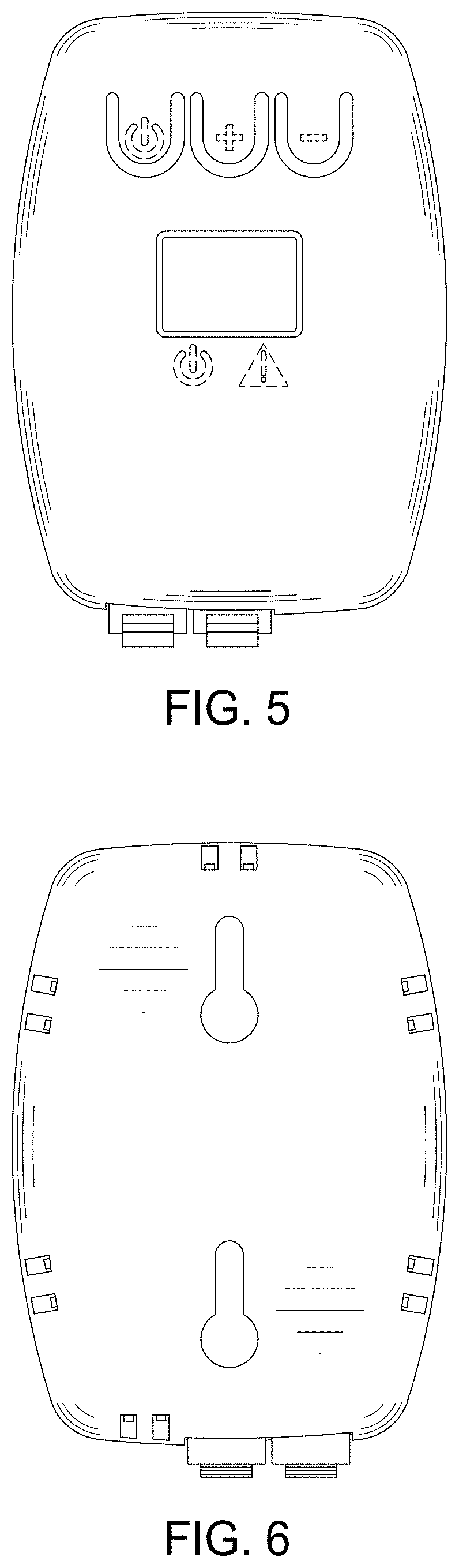
FIG. 5 is a front elevational view thereof.
FIG. 6 is a rear elevational view thereof.
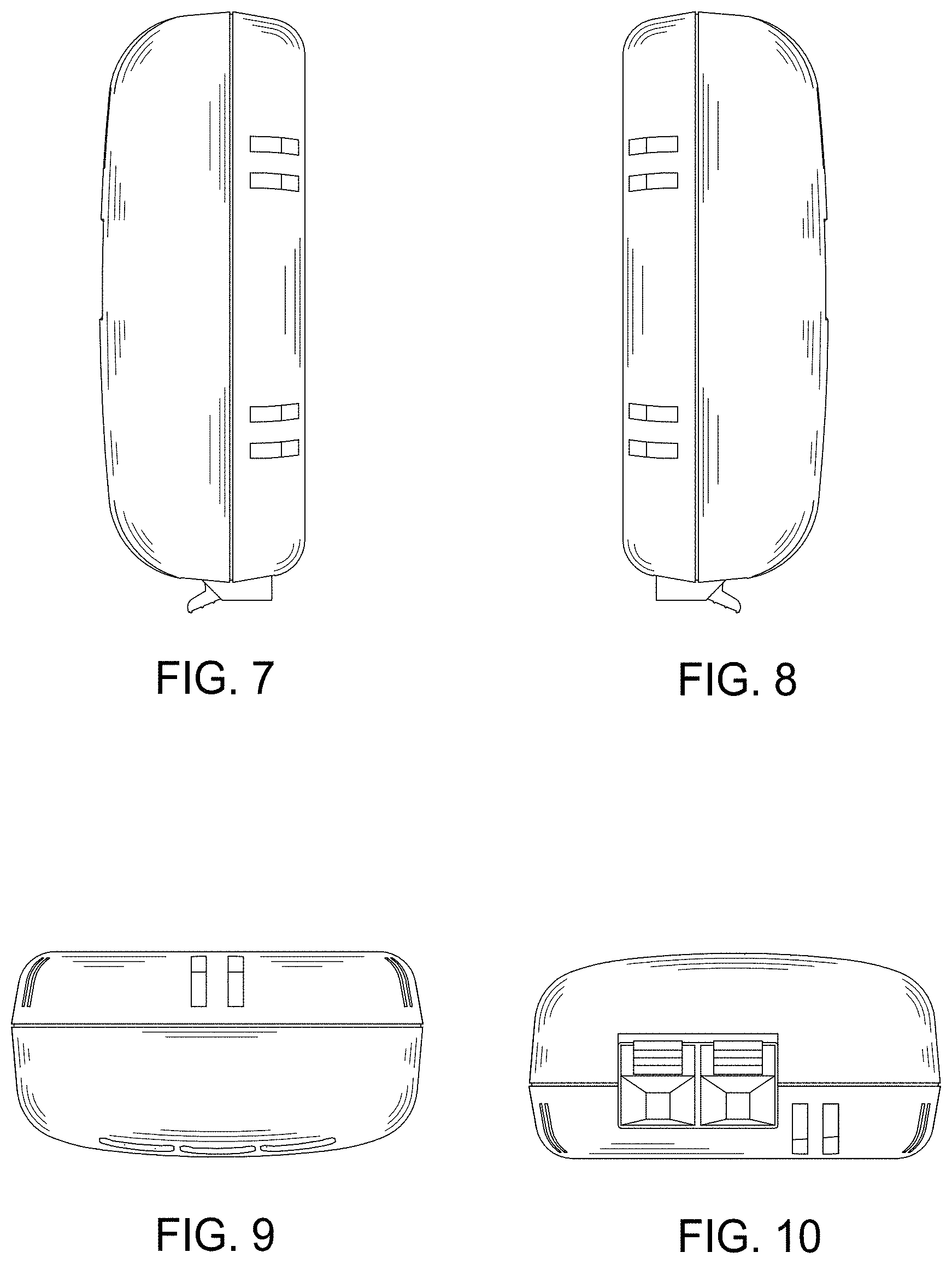
FIG. 7 is a right side elevational view thereof.
FIG. 8 is a left side elevational view thereof.
FIG. 9 is a top plan view thereof; and,
FIG. 10 is a bottom plan view thereof.
The broken lines depict portions of the containment transmitter for pet receiver that form no part of the claimed design.
* * * * *
References
-
petsafe.netforIn-GroundFenceSystemtocontainadog
-
petsafe.netLittleDogIn-GroundFenceSystemtocontainadog
-
petsafe.netforIn-GroundFenceControlSystem
-
petsafe.netforIn-GroundFenceSystemtocontainacat
-
petsafe.netforStubbornDogIn-GroundFenceSystemtocontainadog
-
funace.comforIn-GroundWiredFenceController
-
funace.netforIn-GroundWiredFenceController
D00000
D00001
D00002
D00003
D00004
XML
uspto.report is an independent third-party trademark research tool that is not affiliated, endorsed, or sponsored by the United States Patent and Trademark Office (USPTO) or any other governmental organization. The information provided by uspto.report is based on publicly available data at the time of writing and is intended for informational purposes only.
While we strive to provide accurate and up-to-date information, we do not guarantee the accuracy, completeness, reliability, or suitability of the information displayed on this site. The use of this site is at your own risk. Any reliance you place on such information is therefore strictly at your own risk.
All official trademark data, including owner information, should be verified by visiting the official USPTO website at www.uspto.gov. This site is not intended to replace professional legal advice and should not be used as a substitute for consulting with a legal professional who is knowledgeable about trademark law.