Pad with channel
Glatt
U.S. patent number D883,713 [Application Number D/614,346] was granted by the patent office on 2020-05-12 for pad with channel. The grantee listed for this patent is Terry L. Glatt. Invention is credited to Terry L. Glatt.


View All Diagrams
| United States Patent | D883,713 |
| Glatt | May 12, 2020 |
Pad with channel
Claims
CLAIM I claim the ornamental design for a pad with channel, as shown and described.
| Inventors: | Glatt; Terry L. (Lighthouse Point, FL) | ||||||||||
|---|---|---|---|---|---|---|---|---|---|---|---|
| Applicant: |
|
||||||||||
| Appl. No.: | D/614,346 | ||||||||||
| Filed: | August 17, 2017 |
| Current U.S. Class: | D6/601 |
| Current International Class: | 0609 |
| Field of Search: | ;D1/121,127 ;D6/349,391,596,601 ;D21/500,503,680,686 ;D24/158,159,183,184 ;D25/113,157 ;D28/8.1 ;D30/118,131,160 |
References Cited [Referenced By]
U.S. Patent Documents
| 1580210 | April 1926 | McCulloch |
| 1894605 | January 1933 | Wright |
| 1934918 | November 1933 | Everson |
| 3667074 | June 1972 | Emery |
| 4218792 | August 1980 | Kogan |
| D256728 | September 1980 | Allen |
| 4447922 | May 1984 | Brochu |
| D299069 | December 1988 | Risi |
| 4824174 | April 1989 | Dunn, Sr. |
| 4924246 | May 1990 | Yamada |
| D321562 | November 1991 | Ljungvall |
| D328682 | August 1992 | Carney |
| D330978 | November 1992 | Vasquez |
| 5165130 | November 1992 | Wendling |
| D387109 | December 1997 | Winans |
| D396771 | August 1998 | Iannuzzi |
| D397270 | August 1998 | Maalouf |
| D407820 | April 1999 | Sullenberger |
| 5926880 | July 1999 | Sramek |
| D471050 | March 2003 | Haubner |
| D501933 | February 2005 | Dinter |
| D515709 | February 2006 | Charon |
| D557464 | December 2007 | Novak |
| D560326 | January 2008 | Bruno |
| D576439 | September 2008 | Yaroshenko |
| D601261 | September 2009 | Levan |
| D618354 | June 2010 | Francucci |
| D641948 | July 2011 | Bruyea |
| D641950 | July 2011 | Bruyea |
| D691828 | October 2013 | Rosenberg |
| D713165 | September 2014 | Robinson |
| D748931 | February 2016 | Corigliano |
| D807973 | January 2018 | Leonardo |
| D812780 | March 2018 | Saunders |
| 10448764 | October 2019 | Aydemir |
| 2004/0139548 | July 2004 | Hwang-Pao |
| 2006/0055215 | March 2006 | Potosky |
| 2008/0282474 | November 2008 | Hsin |
| 2009/0139031 | June 2009 | Davis et al. |
| 2013/0263377 | October 2013 | Wootten, Jr. |
| 2013/0305456 | November 2013 | Thompson |
| 2014/0317851 | October 2014 | Hammack et al. |
| 2015/0020814 | January 2015 | Flatau |
| 2015/0366381 | December 2015 | Aydemir |
| 2018/0303259 | October 2018 | Glatt |
Other References
|
"mittaGonG Pillow Memory foram pillow Suitable for eyeglass users." Found online Dec. 12, 2019 at amazon.co.jp. Product first available Jun. 26, 2018. Retrieved from URL: https://tinyurl.com/r59nzoc (Year: 2018). cited by examiner . "Ergonomic Pillow Booster." Found online Dec. 12, 2019 at amazon.co.uk. Product first available Jul. 31, 2016. Retrieved from URL: https://www.amazon.co.uk/ERGONOMIC-shoulder-Provides-cervical-orthopaedic- /dp/B01K5O2CDI (Year: 2016). cited by examiner . "Best pillow for side sleepers with Arm Under--Microbead Cloud." Found online Dec. 12, 2019 at www.bettersleeppillow.com. Product reviewed Sep. 24, 2014. Retrieved from URL: https://www.bettersleeppillow.com/arm-tunnel-pillow-microbead-1.html (Year: 2014). cited by examiner . "The LaySee Pillow." Found online Dec. 12, 2019 at www.amazon.com. Product reviewed Apr. 4, 2018. Retrieved from URL: https://tinyurl.com/qnl5qa7 (Year: 2018). cited by examiner. |
Primary Examiner: Calabrese; Mary Ann
Assistant Examiner: Kloberg; Katelin G
Attorney, Agent or Firm: Pearson IP Pearson; Loren Donald
Description
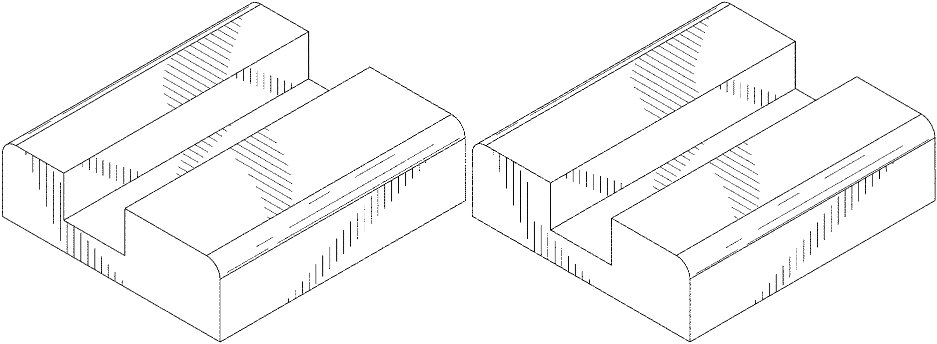
FIG. 1 is a top, front, right side isometric view of a pad with channel, showing a first embodiment of my new design;
FIG. 2 is a bottom, rear, left side isometric view thereof;
FIG. 3 is a top plan view thereof;
FIG. 4 is a bottom plan view thereof;
FIG. 5 is a right side elevation view with the left side being a mirror image thereof;
FIG. 6 is a front elevation view with the rear being a mirror image thereof;
FIG. 7 is a top, front, right side isometric view of a pad with channel, showing a second embodiment of my new design;
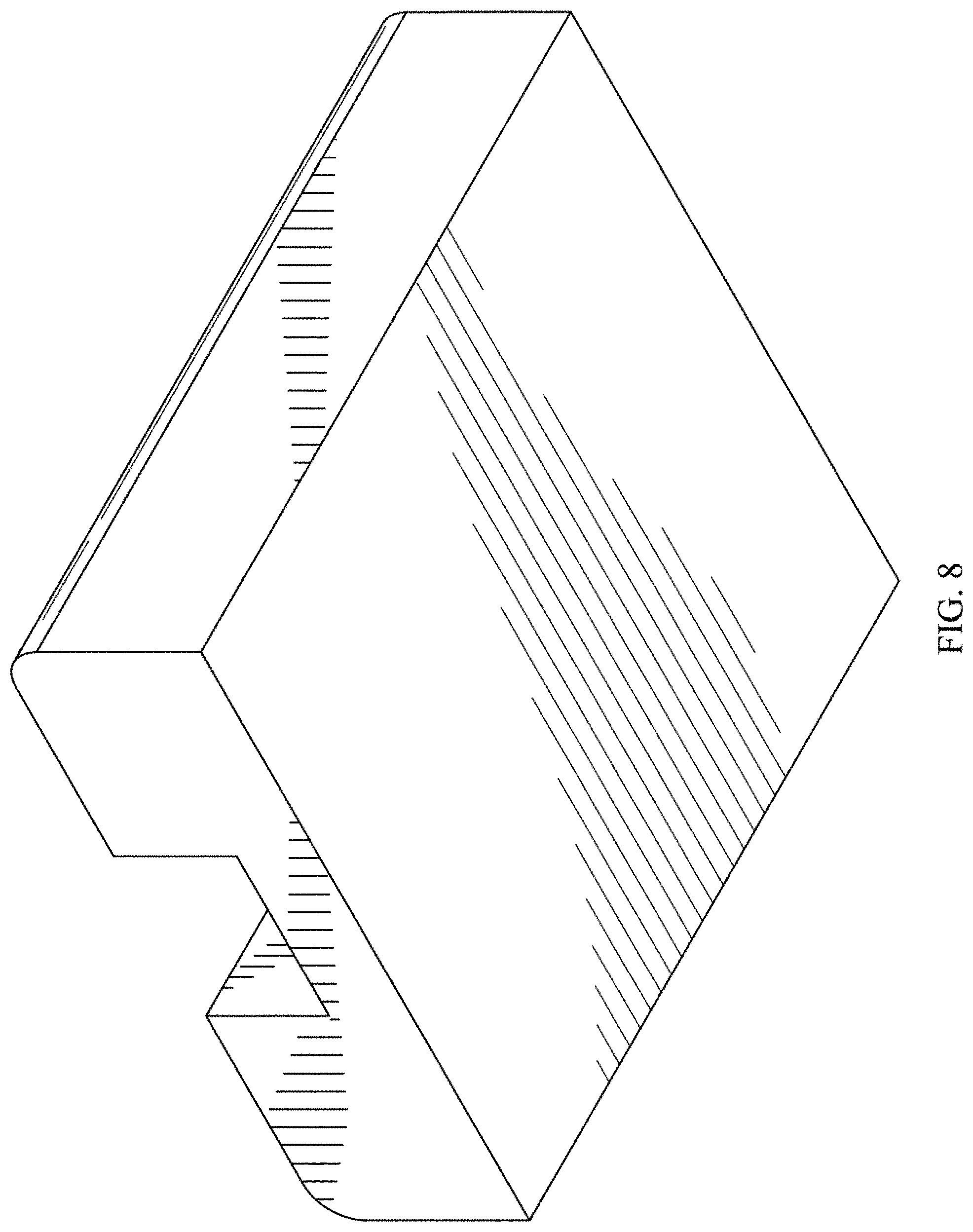
FIG. 8 is a bottom, rear, left side isometric view thereof;
FIG. 9 is a top plan view thereof;
FIG. 10 is a bottom plan view thereof;
FIG. 11 is a right side elevation view with the left side being a mirror image thereof;
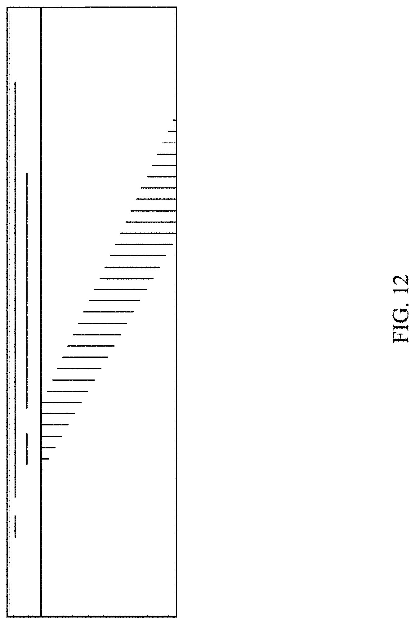
FIG. 12 is a front elevation view with the rear being a mirror image thereof;
FIG. 13 is a top, front, right side isometric view of a pad with channel, showing a third embodiment of my new design;
FIG. 14 is a bottom, rear, left side isometric view thereof;
FIG. 15 is a top plan view thereof;
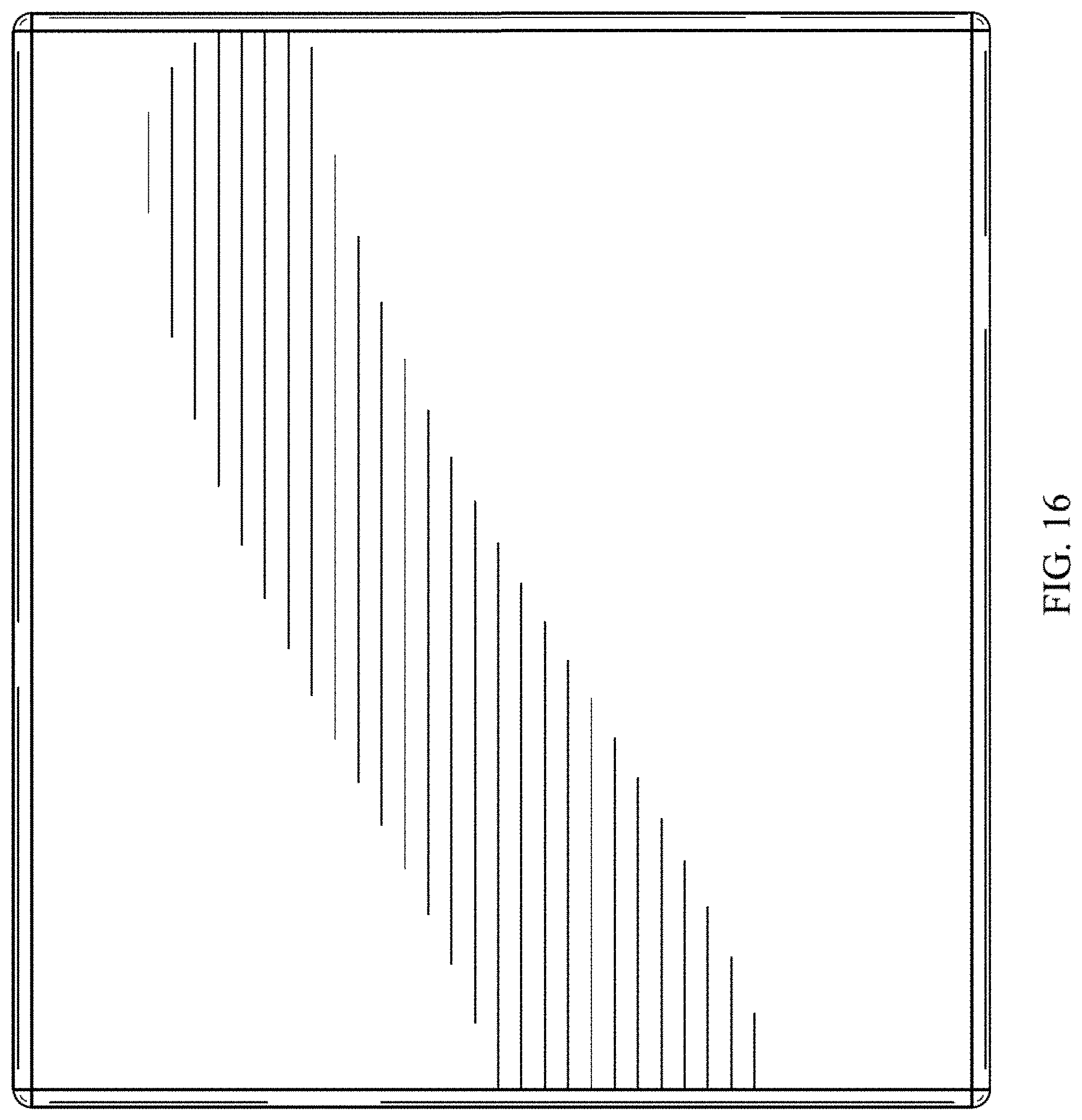
FIG. 16 is a bottom plan view thereof;
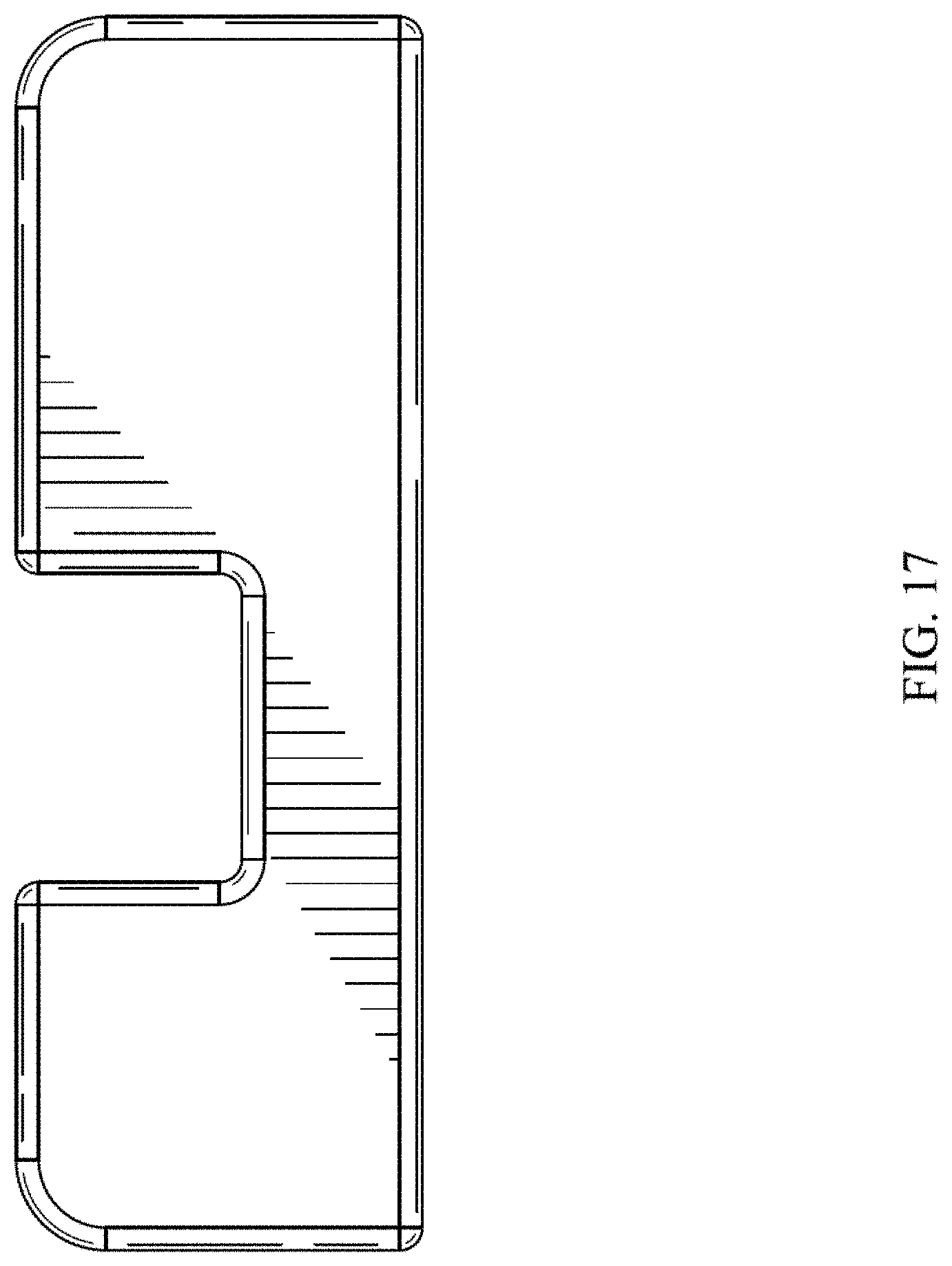
FIG. 17 is a right side elevation view with the left side being a mirror image thereof;
FIG. 18 is a front elevation view with the rear being a mirror image thereof;
FIG. 19 is a top, front, right side isometric view of a pad with channel, showing a fourth embodiment of my new design;
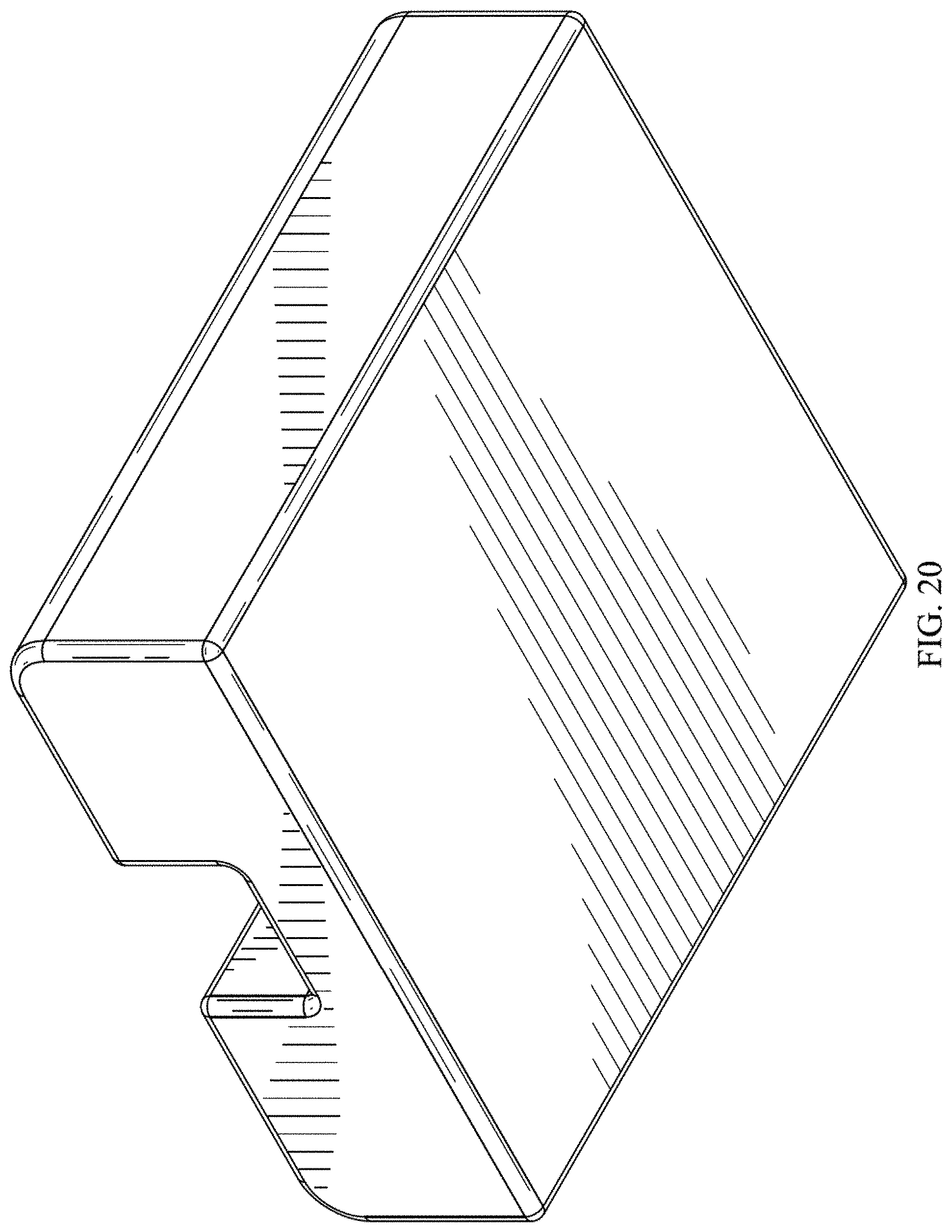
FIG. 20 is a bottom, rear, left side isometric view thereof;
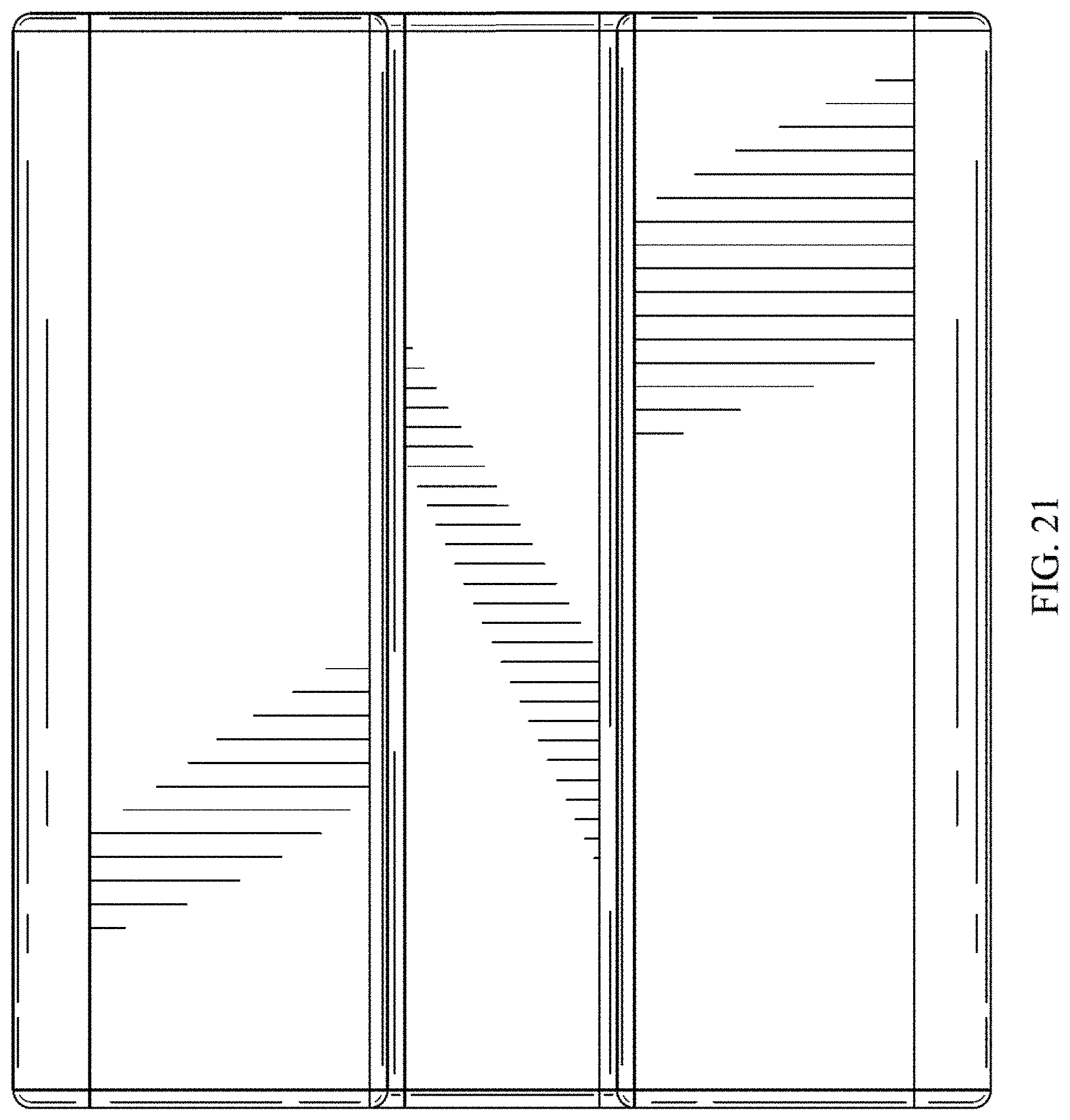
FIG. 21 is a top plan view thereof;
FIG. 22 is a bottom plan view thereof;
FIG. 23 is a right side elevation view with the left side being a mirror image thereof; and,
FIG. 24 is a front elevation view with the rear being a mirror image thereof.
* * * * *
References
D00000
D00001
D00002
D00003
D00004
D00005
D00006
D00007
D00008
D00009
D00010
D00011
D00012
D00013

D00014

D00015

D00016
D00017
D00018

D00019

D00020
D00021
D00022

D00023

D00024

XML
uspto.report is an independent third-party trademark research tool that is not affiliated, endorsed, or sponsored by the United States Patent and Trademark Office (USPTO) or any other governmental organization. The information provided by uspto.report is based on publicly available data at the time of writing and is intended for informational purposes only.
While we strive to provide accurate and up-to-date information, we do not guarantee the accuracy, completeness, reliability, or suitability of the information displayed on this site. The use of this site is at your own risk. Any reliance you place on such information is therefore strictly at your own risk.
All official trademark data, including owner information, should be verified by visiting the official USPTO website at www.uspto.gov. This site is not intended to replace professional legal advice and should not be used as a substitute for consulting with a legal professional who is knowledgeable about trademark law.