Eye exam apparatus
Katz , et al.
U.S. patent number D882,094 [Application Number D/640,840] was granted by the patent office on 2020-04-21 for eye exam apparatus. This patent grant is currently assigned to GlobeChek Enterprises, LLC. The grantee listed for this patent is GLOBECHEK ENTERPRISES, LLC. Invention is credited to Adam M. Katz, William J. Mallon.
| United States Patent | D882,094 |
| Katz , et al. | April 21, 2020 |
Eye exam apparatus
Claims
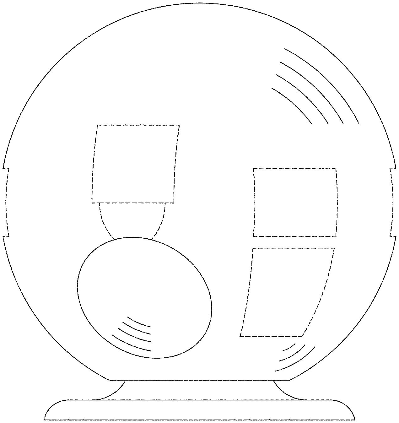
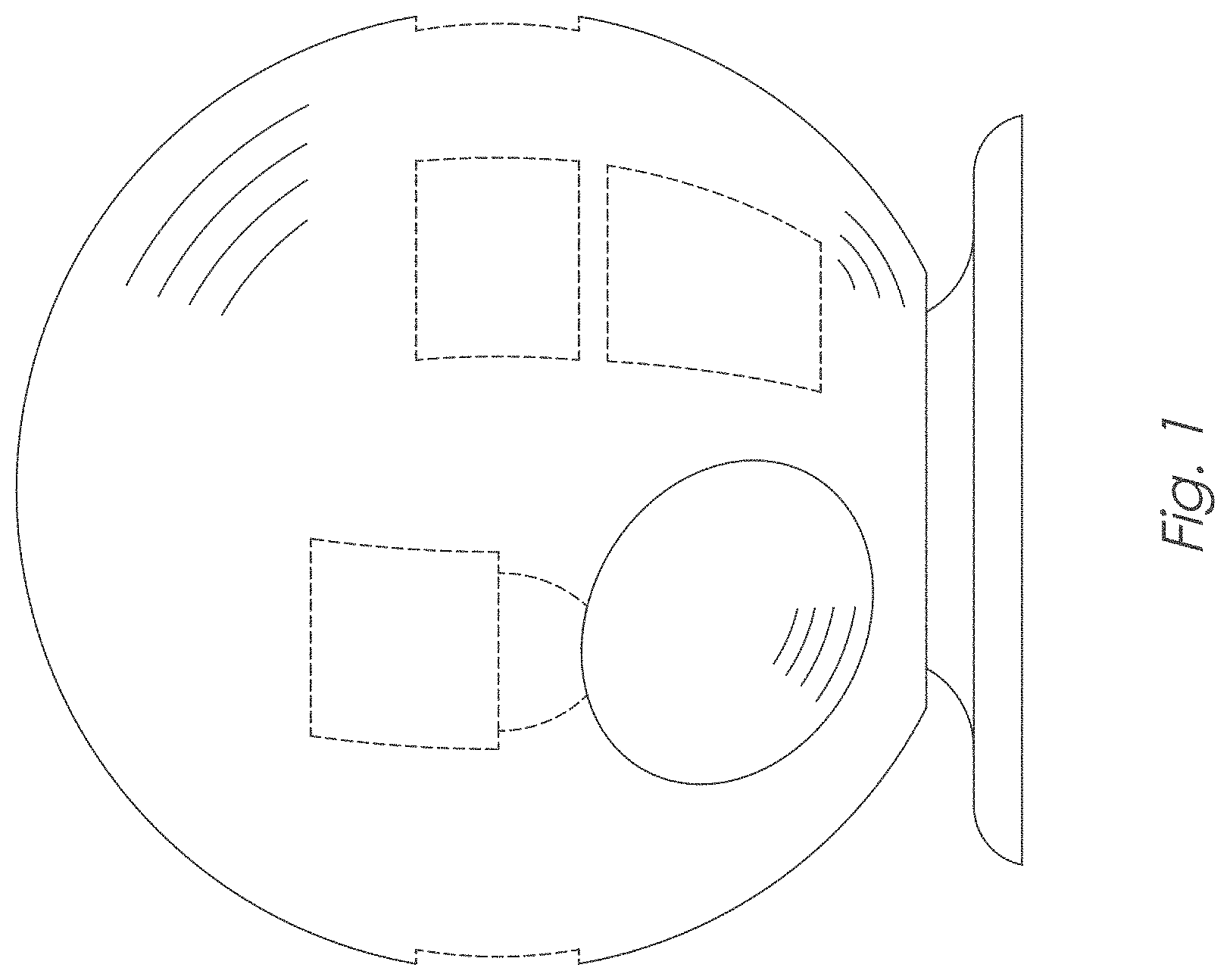
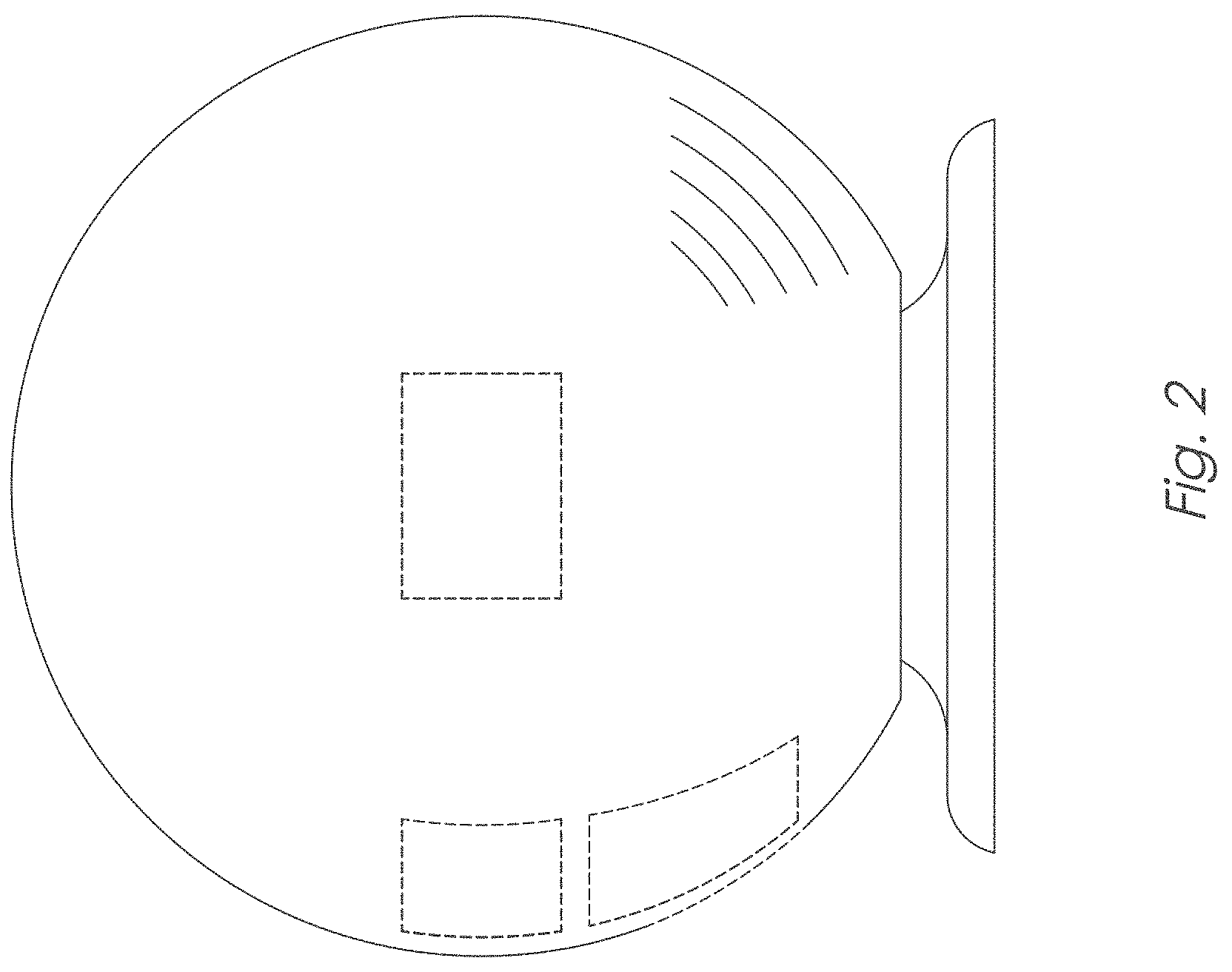
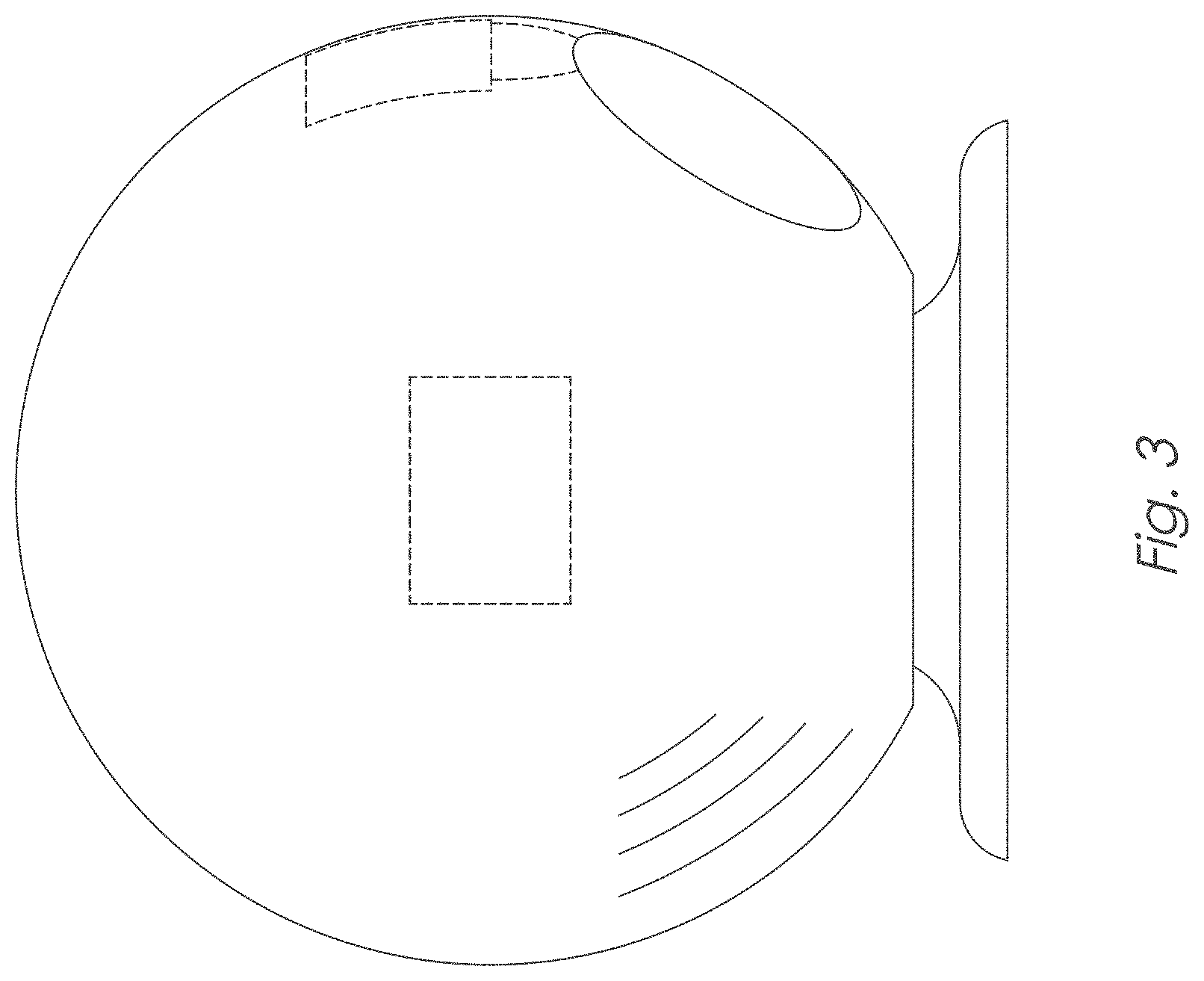
CLAIM The ornamental design for an eye exam apparatus, as shown and described.
| Inventors: | Katz; Adam M. (Vero Beach, FL), Mallon; William J. (Vero Beach, FL) | ||||||||||
|---|---|---|---|---|---|---|---|---|---|---|---|
| Applicant: |
|
||||||||||
| Assignee: | GlobeChek Enterprises, LLC
(Vero Beach, FL) |
||||||||||
| Family ID: | 61617615 | ||||||||||
| Appl. No.: | D/640,840 | ||||||||||
| Filed: | March 16, 2018 |
Related U.S. Patent Documents
| Application Number | Filing Date | Patent Number | Issue Date | ||
|---|---|---|---|---|---|
| PCT/US2017/051946 | Sep 17, 2017 | ||||
| Current U.S. Class: | D24/172 |
| Current CPC Class: | A61B3/14 20130101; A61B3/103 20130101; A61B3/102 20130101; A61B3/18 20130101; A61B3/165 20130101; A61B3/024 20130101; A61B3/0083 20130101; A61B3/13 20130101; A61B3/107 20130101; A61B3/0025 20130101 |
| Current International Class: | 2402 |
| Field of Search: | ;D24/172,183,185,168,209 ;D25/19,31,13,16,10 ;D20/29,10 ;D21/709 ;D99/28 |
References Cited [Referenced By]
U.S. Patent Documents
| 3477779 | November 1969 | Tadayoshi |
| D233371 | October 1974 | Fila |
| 3908790 | September 1975 | Phelps, Jr. |
| D245866 | September 1977 | Schuldenfrei |
| D252410 | July 1979 | Graser |
| 4174594 | November 1979 | Panzini |
| D255719 | July 1980 | Panzini |
| D279711 | July 1985 | English |
| D327376 | June 1992 | Piccamiglio |
| D379375 | May 1997 | Bowman |
| D396115 | July 1998 | Zobel, Jr. |
| D545977 | July 2007 | Kluska |
| D605306 | December 2009 | Arnell |
| D668720 | October 2012 | Mascarelli |
| D693479 | November 2013 | McCall |
| D694890 | December 2013 | Bott |
| D735342 | July 2015 | Asad |
| D737450 | August 2015 | Abelson |
| D746472 | December 2015 | Morgan |
| D756041 | May 2016 | Robbins, III |
| D819214 | May 2018 | Katz |
Attorney, Agent or Firm: Thomas; Stephen C.
Description
FIG. 1 is a front view of the eye exam apparatus, showing our new design;
FIG. 2 is a right side view thereof;
FIG. 3 is a left side view thereof;
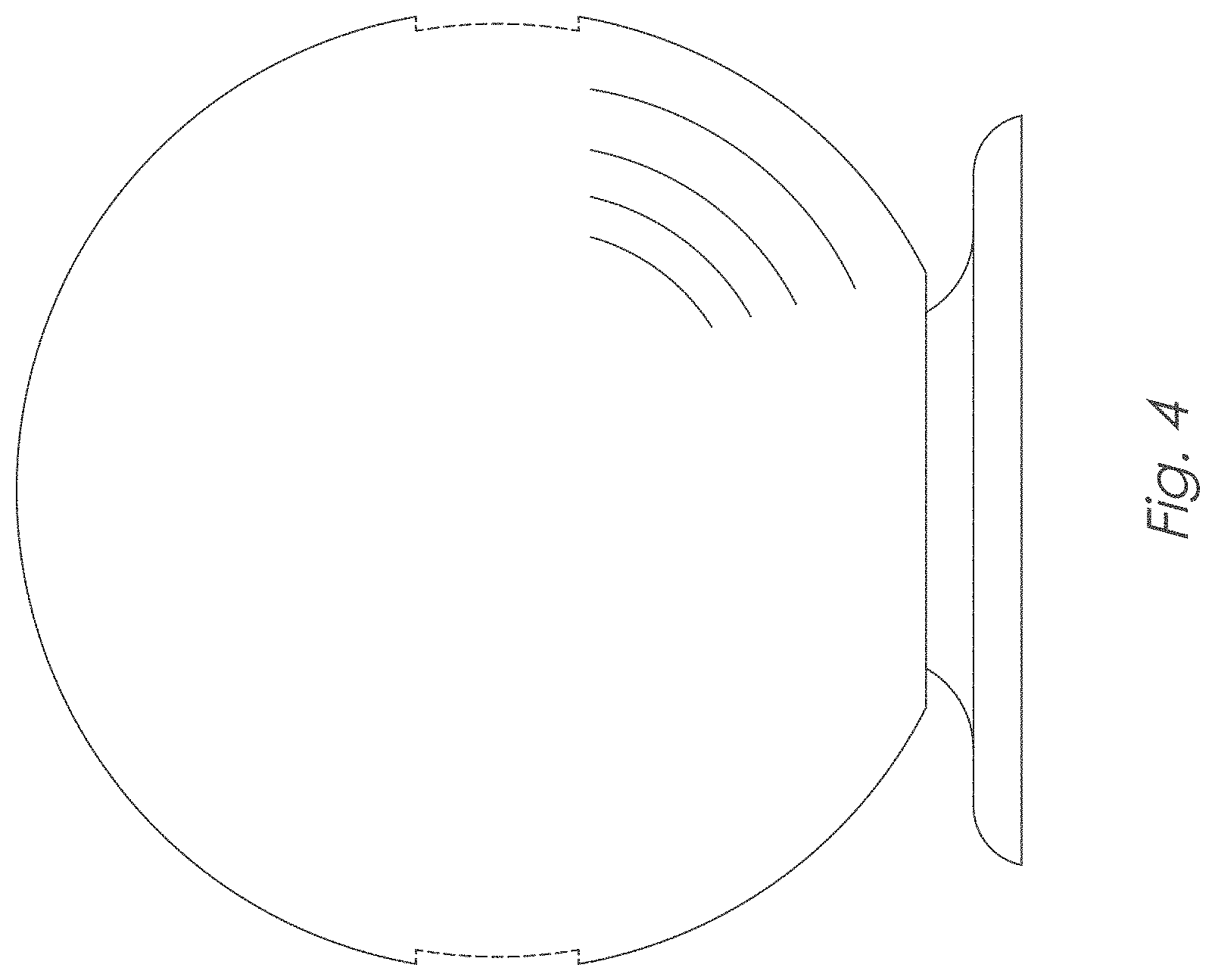
FIG. 4 is a rear view thereof;
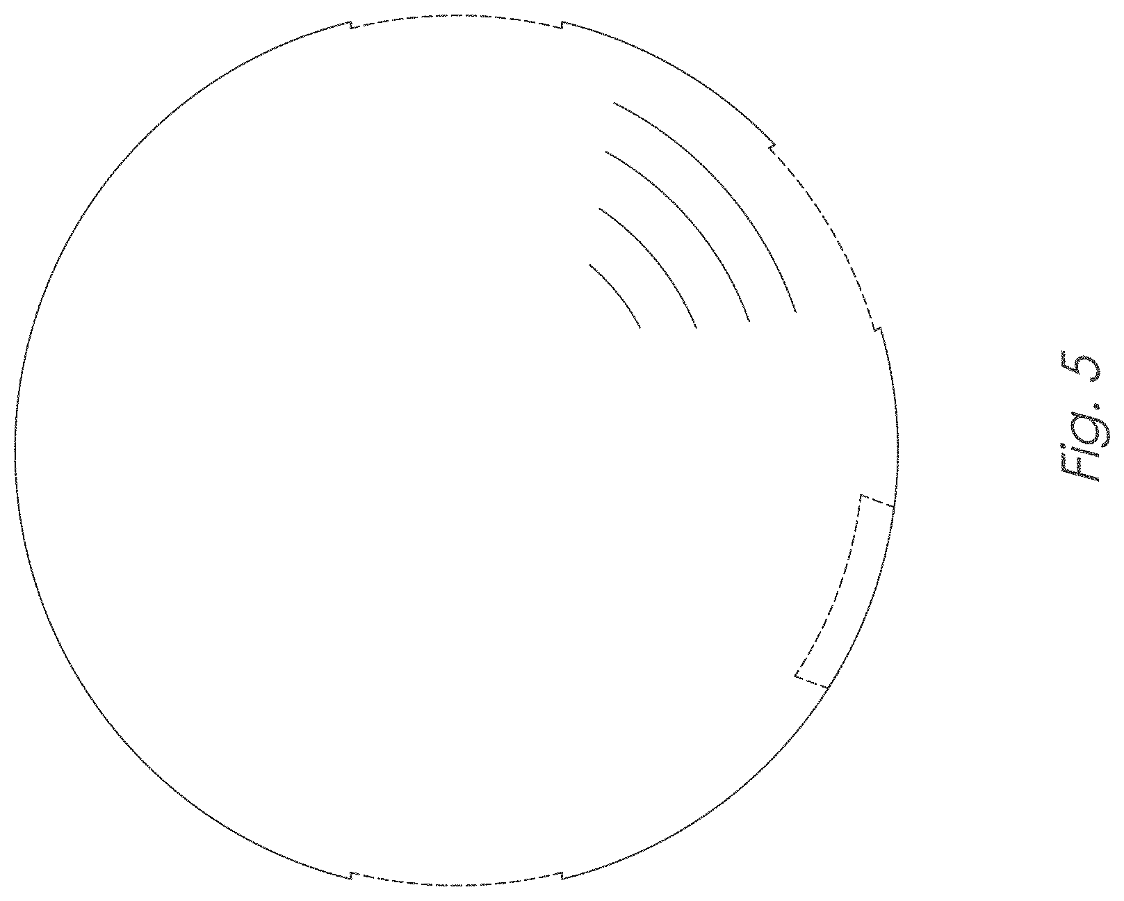
FIG. 5 is a top view thereof; and,
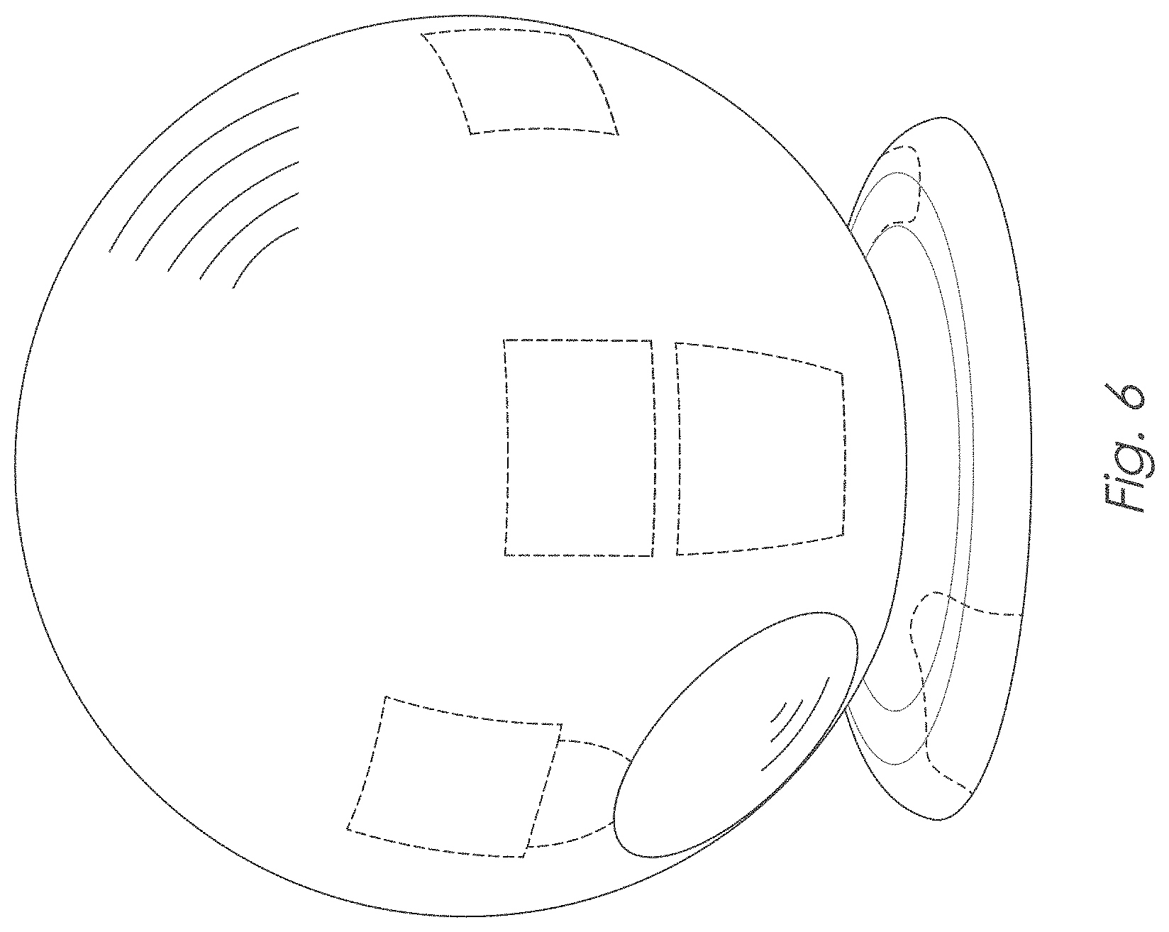
FIG. 6 is a perspective view thereof.
In the drawings, the broken lines are for the purpose of illustrating portions of the eye exam apparatus that form no part of the claimed design.
* * * * *
D00000
D00001
D00002
D00003
D00004
D00005
D00006
XML
uspto.report is an independent third-party trademark research tool that is not affiliated, endorsed, or sponsored by the United States Patent and Trademark Office (USPTO) or any other governmental organization. The information provided by uspto.report is based on publicly available data at the time of writing and is intended for informational purposes only.
While we strive to provide accurate and up-to-date information, we do not guarantee the accuracy, completeness, reliability, or suitability of the information displayed on this site. The use of this site is at your own risk. Any reliance you place on such information is therefore strictly at your own risk.
All official trademark data, including owner information, should be verified by visiting the official USPTO website at www.uspto.gov. This site is not intended to replace professional legal advice and should not be used as a substitute for consulting with a legal professional who is knowledgeable about trademark law.