Camera
Zhang
U.S. patent number D881,967 [Application Number D/633,532] was granted by the patent office on 2020-04-21 for camera. The grantee listed for this patent is Shen Zhen Shi Ju Hui Tao Jin Chu Kou Co., Ltd.. Invention is credited to Changlin Zhang.


| United States Patent | D881,967 |
| Zhang | April 21, 2020 |
Camera
Claims
CLAIM The ornamental design for a camera, as shown and described.
| Inventors: | Zhang; Changlin (XinJiang, CN) | ||||||||||
|---|---|---|---|---|---|---|---|---|---|---|---|
| Applicant: |
|
||||||||||
| Appl. No.: | D/633,532 | ||||||||||
| Filed: | January 15, 2018 |
| Current U.S. Class: | D16/203 |
| Current International Class: | 1601 |
| Field of Search: | ;D16/200-220,131,237,242,239,250,235,130,134,136,238 ;D14/138C,240,248,203.1,203.3,203.7,218,207 ;D10/104.1,50,65,74,70,118.2 ;D26/28,29,34,51,52,60,61,722 ;D3/260 ;D30/109,104,106,107 ;D22/136 |
References Cited [Referenced By]
U.S. Patent Documents
| D410479 | June 1999 | Sawai |
| D462068 | August 2002 | Solland |
| D485544 | January 2004 | Solland |
| D552650 | October 2007 | Yamakawa |
| 7724302 | May 2010 | Yu |
| D626984 | November 2010 | Miyaji |
| D663731 | July 2012 | Pajic |
| D685438 | July 2013 | Fan |
| D690344 | September 2013 | Hollinger |
| D725514 | March 2015 | Broadbent |
| D741931 | October 2015 | Huang |
| D742955 | November 2015 | Kozko |
| D746276 | December 2015 | Schumaker |
| D751619 | March 2016 | Jeong |
| D752544 | March 2016 | Chen |
| D752548 | March 2016 | Chen |
| D752675 | March 2016 | Ravat |
| D753204 | April 2016 | Luo |
| D753206 | April 2016 | Ravat |
| D757835 | May 2016 | Tabuchi |
| D760648 | July 2016 | Lee |
| D776739 | January 2017 | Urashima |
| D777235 | January 2017 | Jang |
| D793363 | August 2017 | Zhang |
| D813290 | March 2018 | Song |
| D813926 | March 2018 | Shin |
| D815172 | April 2018 | Noh |
| D815677 | April 2018 | Gao |
| D816756 | May 2018 | Chang |
| D819109 | May 2018 | Yamauchi |
| D819110 | May 2018 | Chang |
| D819112 | May 2018 | Kim |
| D819718 | June 2018 | Wu |
| D820337 | June 2018 | Li |
| D824984 | August 2018 | Zhiyong |
| D833503 | November 2018 | Hollinger |
| D834634 | November 2018 | Huang |
| D836151 | December 2018 | Chang |
| D836690 | December 2018 | Kim |
| D836698 | December 2018 | Hathway |
| D838758 | January 2019 | Kymm |
| D849094 | May 2019 | Gan |
| D849100 | May 2019 | Hsu |
| D850511 | June 2019 | Matsumoto |
| D863402 | October 2019 | Guo |
| 2006/0017842 | January 2006 | Jun |
| 2017/0230580 | August 2017 | Ohara |
| 2018/0220548 | August 2018 | Onuchin |
| 300924705 | May 2009 | CN | |||
| 302322232 | Feb 2013 | CN | |||
| 302815669 | May 2014 | CN | |||
| 303509413 | Dec 2015 | CN | |||
| 303509481 | Dec 2015 | CN | |||
| 303635231 | Apr 2016 | CN | |||
| 002293084-0001 | Nov 2013 | EM | |||
Assistant Examiner: Ramirez; Mary Claire
Attorney, Agent or Firm: Nama; Prakash Global IP Services, PLLC
Description
FIG. 1 is a front elevational view of a camera showing my new design;
FIG. 2 is a rear elevational view thereof;
FIG. 3 is a left side view thereof;
FIG. 4 is a right side view thereof;
FIG. 5 is a top plan view thereof;
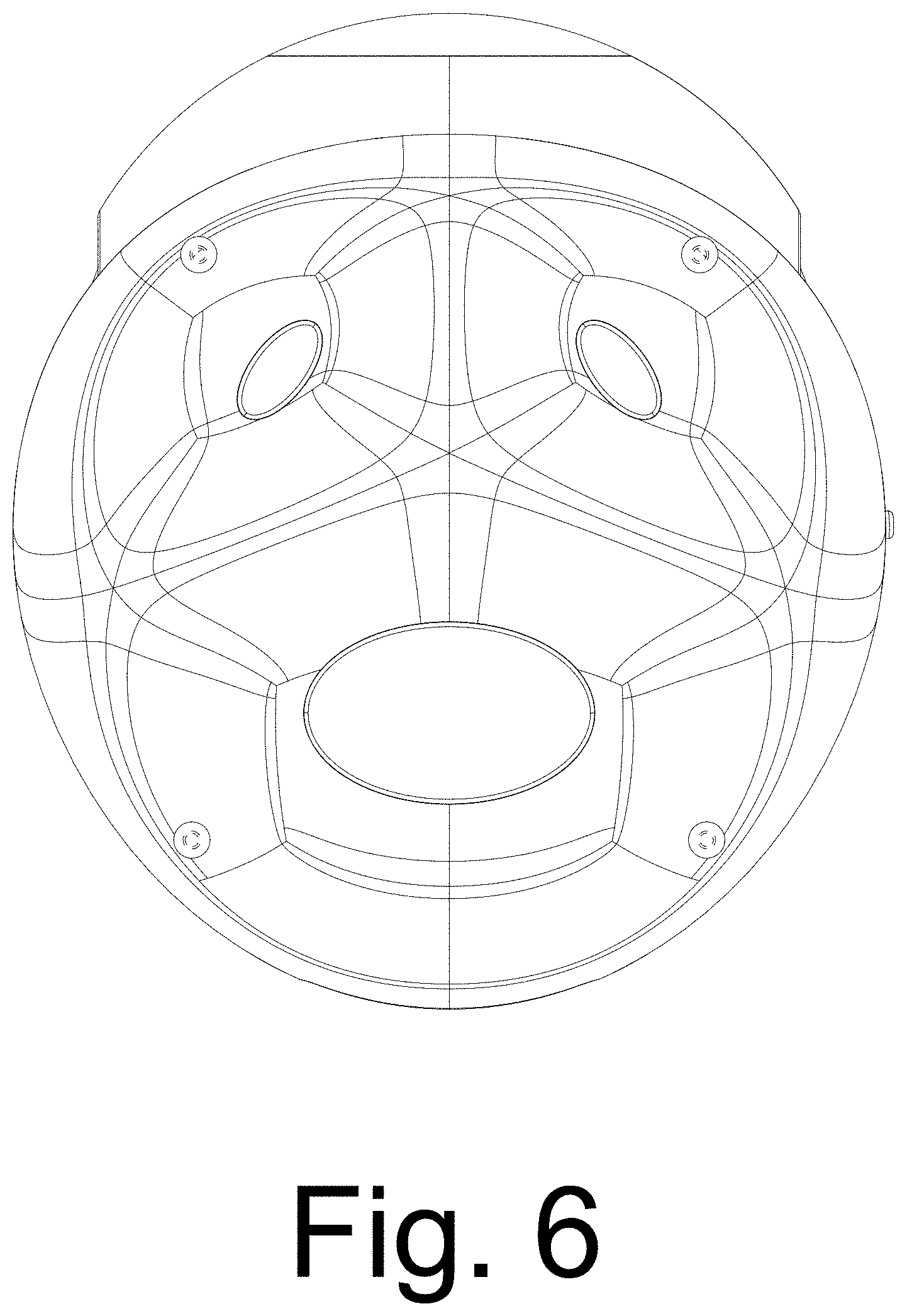
FIG. 6 is a bottom plan view thereof;
FIG. 7 is a perspective view thereof;
FIG. 8 is a second perspective view thereof;
FIG. 9 is a third perspective view thereof; and,
FIG. 10 is a fourth perspective view thereof.
The broken lines shown in the drawings depict portions of the camera that form no part of the claimed design.
* * * * *
D00000
D00001
D00002
D00003
D00004
D00005
D00006
D00007
D00008
D00009
D00010
XML
uspto.report is an independent third-party trademark research tool that is not affiliated, endorsed, or sponsored by the United States Patent and Trademark Office (USPTO) or any other governmental organization. The information provided by uspto.report is based on publicly available data at the time of writing and is intended for informational purposes only.
While we strive to provide accurate and up-to-date information, we do not guarantee the accuracy, completeness, reliability, or suitability of the information displayed on this site. The use of this site is at your own risk. Any reliance you place on such information is therefore strictly at your own risk.
All official trademark data, including owner information, should be verified by visiting the official USPTO website at www.uspto.gov. This site is not intended to replace professional legal advice and should not be used as a substitute for consulting with a legal professional who is knowledgeable about trademark law.