Pulmonary artery stent
Qiu , et al.
U.S. patent number D881,396 [Application Number D/674,254] was granted by the patent office on 2020-04-14 for pulmonary artery stent. This patent grant is currently assigned to Beijing Med-Zenith, Medical Scientific Co., Ltd.. The grantee listed for this patent is Beijing Med-Zenith Medical Scientific Co., Ltd.. Invention is credited to Danian Ke, Jian Meng, Qin Qiu, Qingliang Zhou.
| United States Patent | D881,396 |
| Qiu , et al. | April 14, 2020 |
Pulmonary artery stent
Claims
CLAIM The ornamental design for a pulmonary artery stent, as shown and described.
| Inventors: | Qiu; Qin (Beijing, CN), Zhou; Qingliang (Beijing, CN), Meng; Jian (Beijing, CN), Ke; Danian (Beijing, CN) | ||||||||||
|---|---|---|---|---|---|---|---|---|---|---|---|
| Applicant: |
|
||||||||||
| Assignee: | Beijing Med-Zenith, Medical
Scientific Co., Ltd. (Beijing, CN) |
||||||||||
| Appl. No.: | D/674,254 | ||||||||||
| Filed: | December 20, 2018 |
Foreign Application Priority Data
| Aug 14, 2018 [CN] | 2018 3 0447346 | |||
| Current U.S. Class: | D24/155 |
| Current International Class: | 2403 |
| Field of Search: | ;D24/155 |
References Cited [Referenced By]
U.S. Patent Documents
| D665079 | August 2012 | Zago |
| D665080 | August 2012 | Zago |
| D723165 | February 2015 | Chanduszko |
| D723166 | February 2015 | Igaki |
| D740427 | October 2015 | McDonnell |
| 2003/0055485 | March 2003 | Lee |
| 2011/0106239 | May 2011 | Goto |
Attorney, Agent or Firm: Berggren LLP Somersalo; Leea Susanne
Description
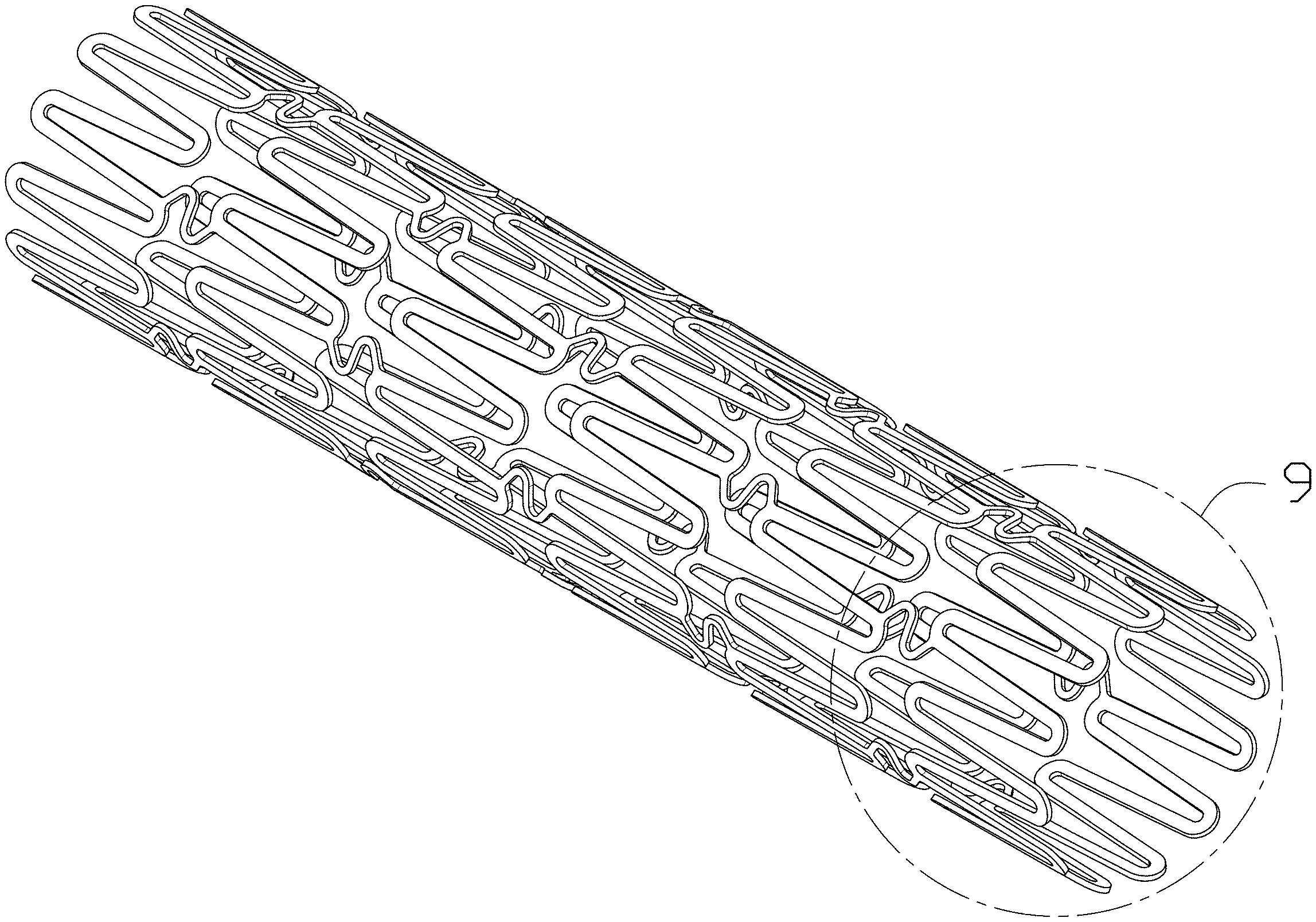
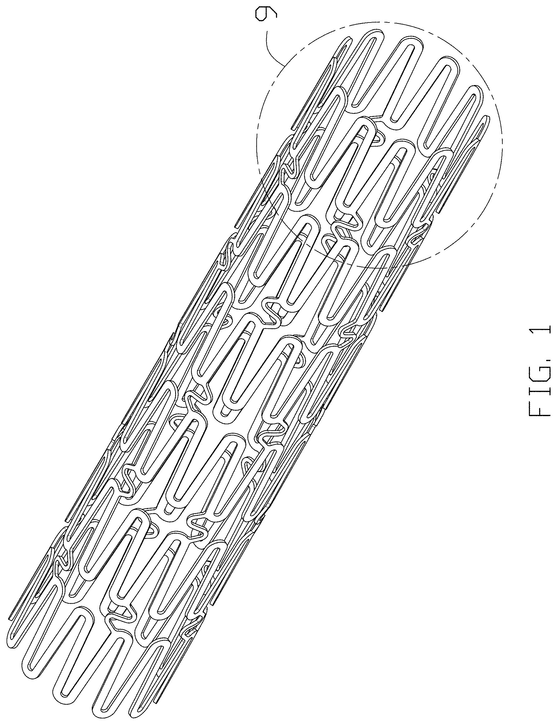
FIG. 1 is an isometric perspective view of the pulmonary artery stent;
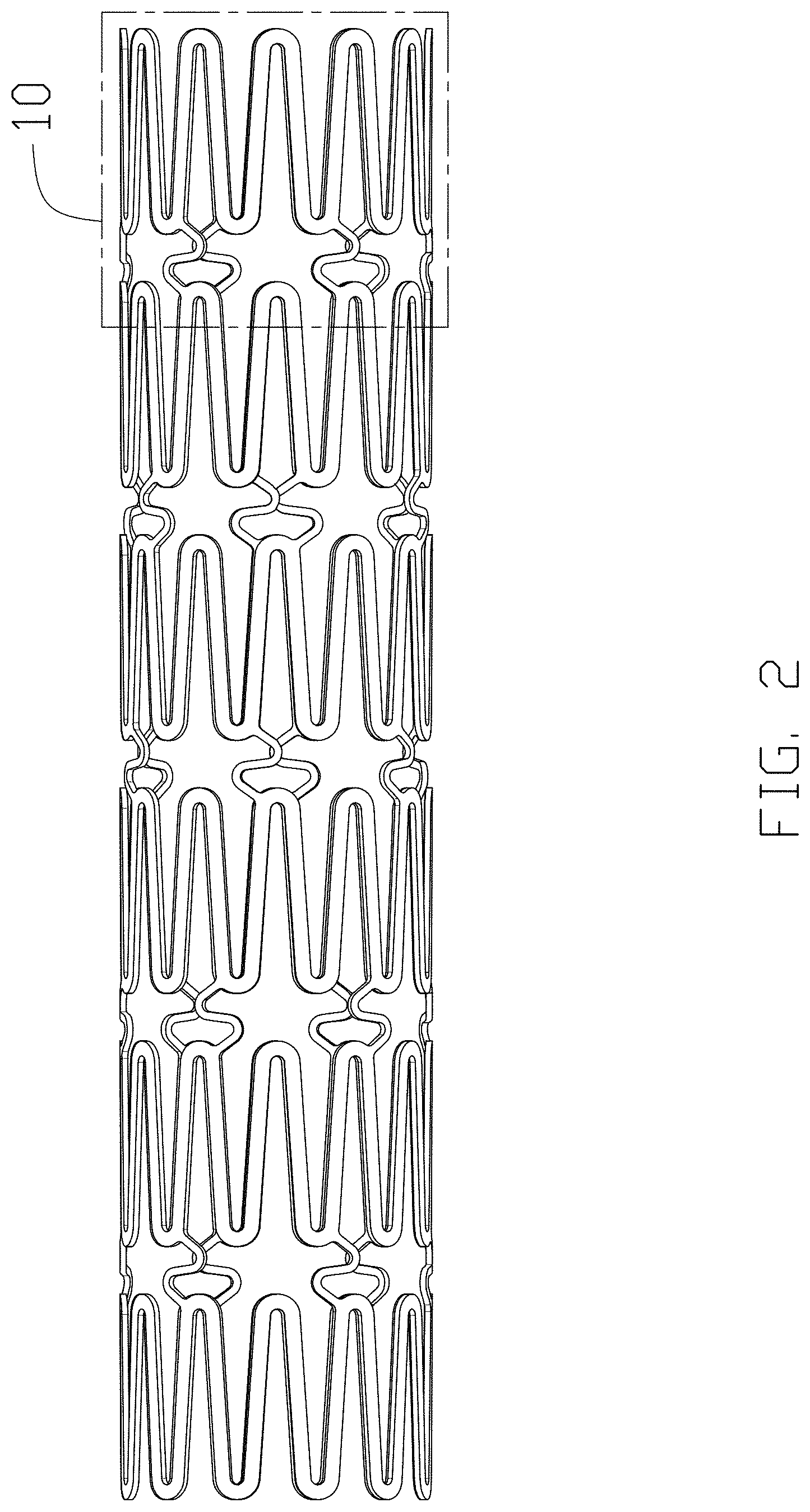
FIG. 2 is the front view thereof;
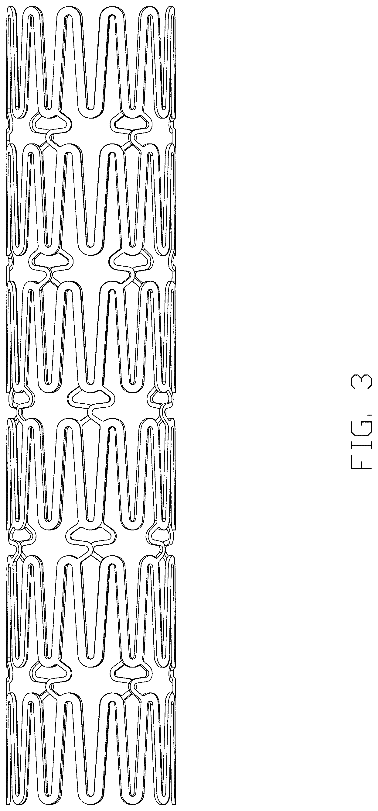
FIG. 3 is the rear view thereof;
FIG. 4 is the top view thereof;
FIG. 5 is the bottom view thereof;
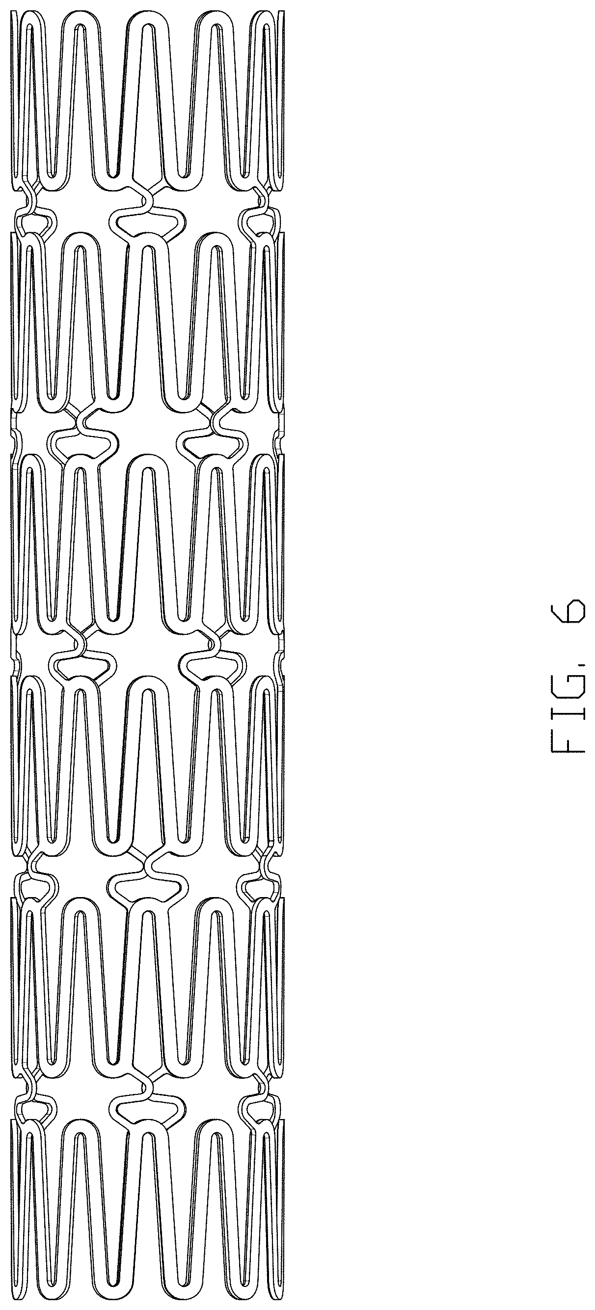
FIG. 6 is left-side view thereof;
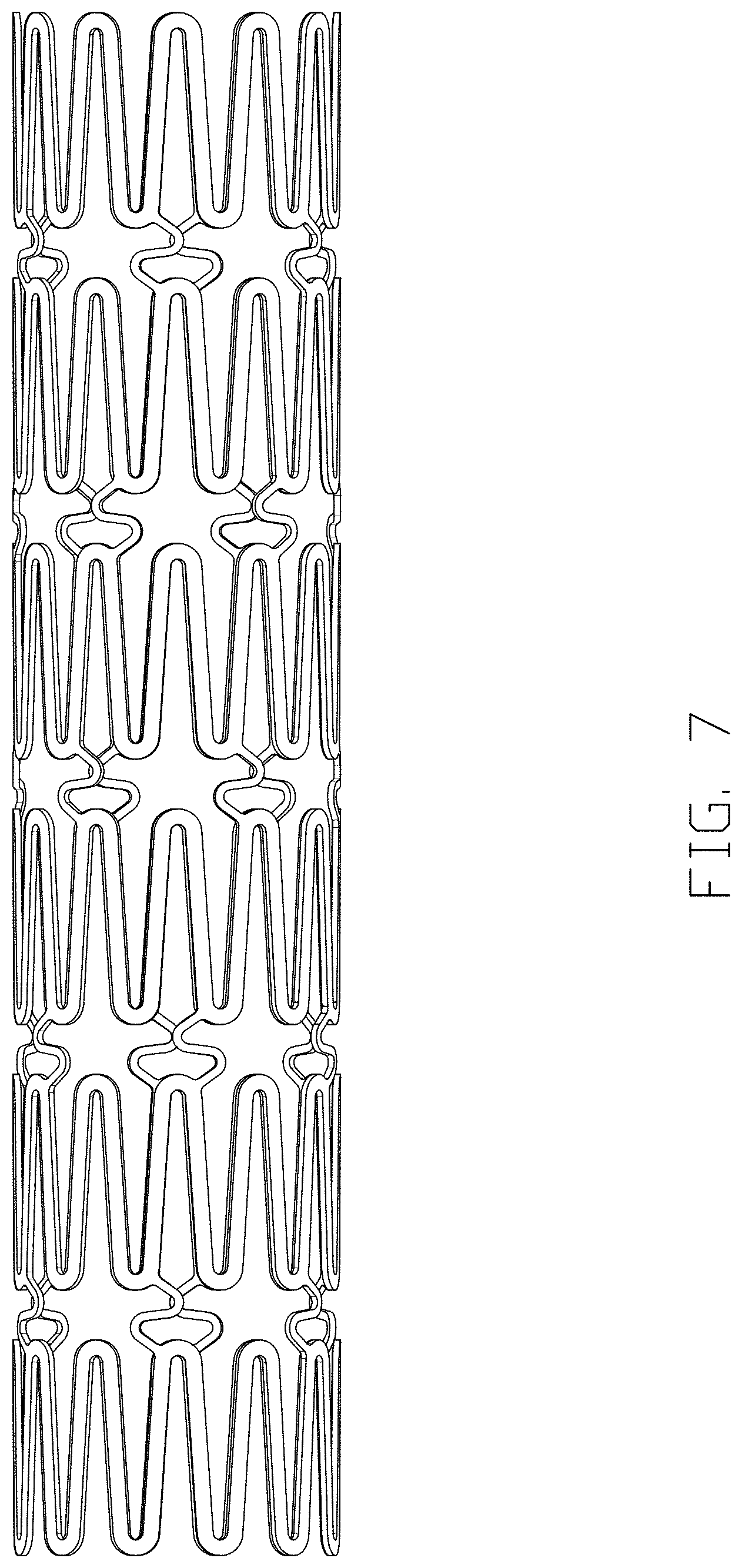
FIG. 7 is right-side view thereof;
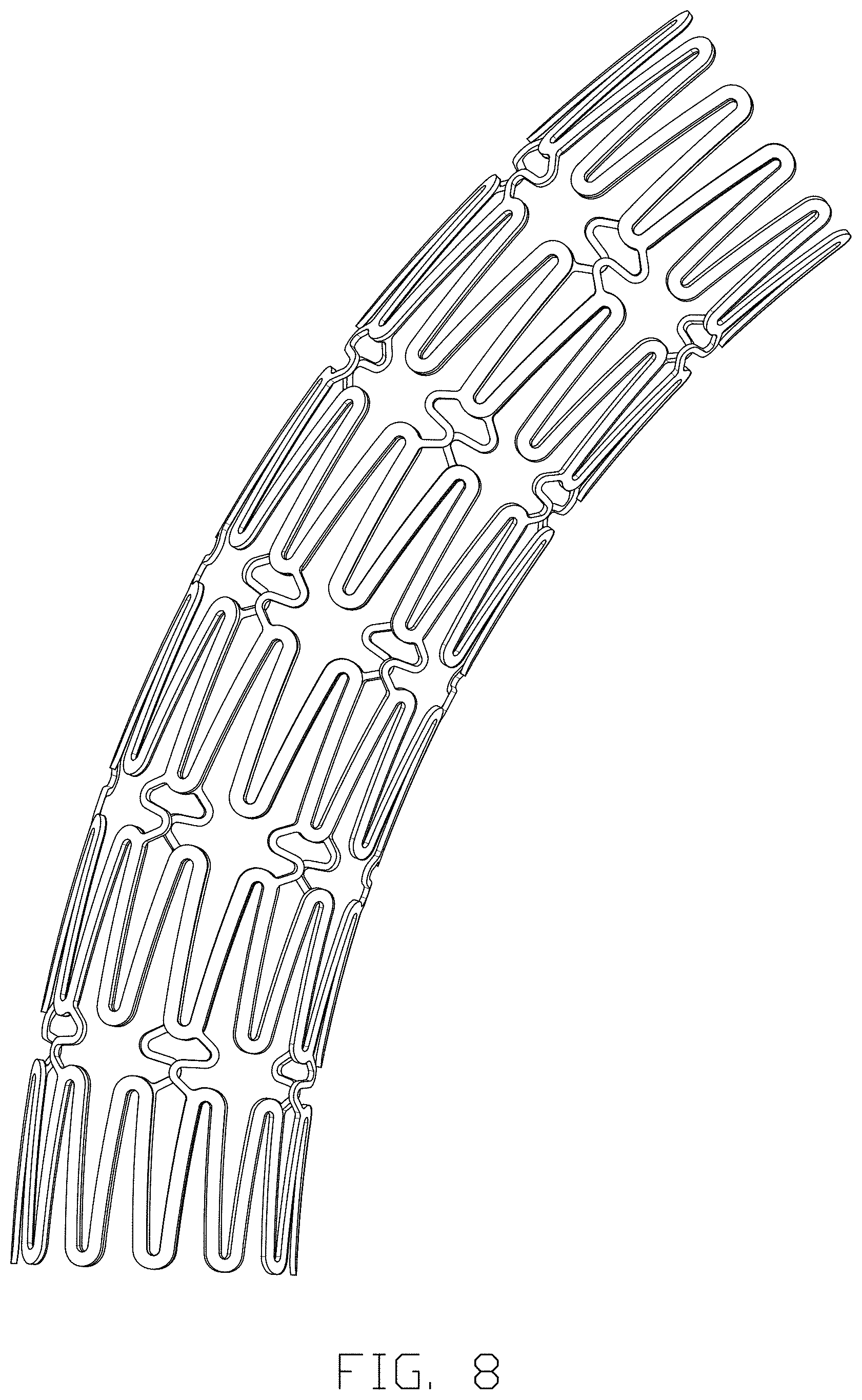
FIG. 8 shows a deformed view thereof;
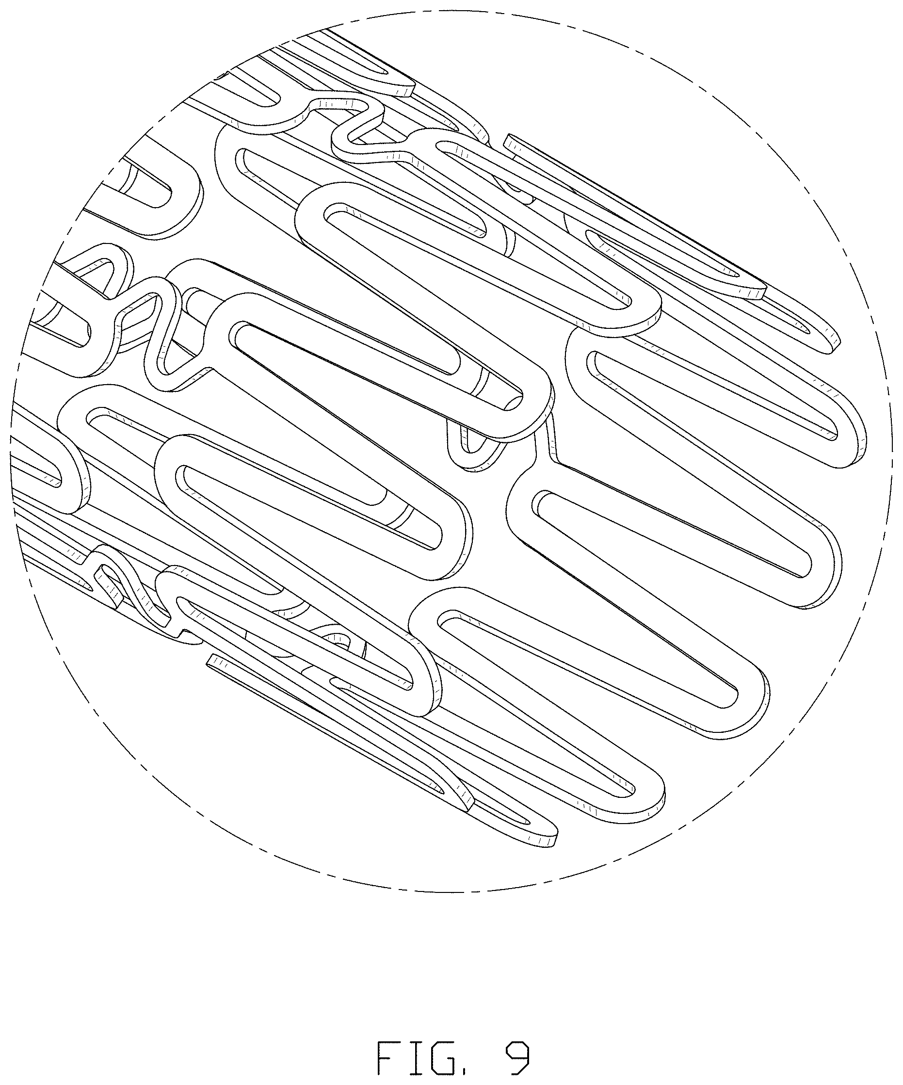
FIG. 9 shows an enlarged isometric perspective view of the enclosed area of FIG. 1; and,
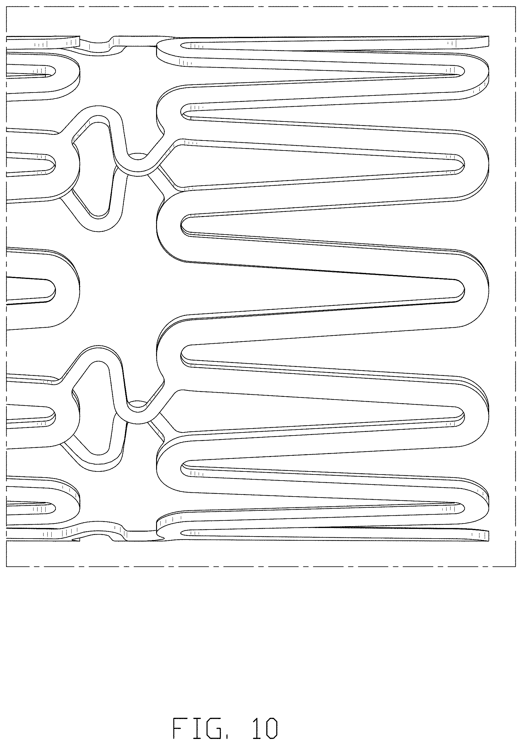
FIG. 10 shows an enlarged view of the enclosed area of FIG. 2.
The broken lines in FIG. 1 are for the purpose of illustrating the end of the pulmonary artery stent, shown in FIG. 9 and form no part of the claimed design.
The broken lines in FIG. 2 are for the purpose of illustrating the end of the pulmonary artery stent, shown in FIG. 10, and form no part of the claimed design.
The broken lines in FIG. 9 define the bounds of the claimed design and form no part thereof.
The broken lines in FIG. 10 define the bounds of the claimed design and form no part thereof.
* * * * *
D00000
D00001
D00002
D00003
D00004
D00005
D00006
D00007
D00008
D00009
D00010
XML
uspto.report is an independent third-party trademark research tool that is not affiliated, endorsed, or sponsored by the United States Patent and Trademark Office (USPTO) or any other governmental organization. The information provided by uspto.report is based on publicly available data at the time of writing and is intended for informational purposes only.
While we strive to provide accurate and up-to-date information, we do not guarantee the accuracy, completeness, reliability, or suitability of the information displayed on this site. The use of this site is at your own risk. Any reliance you place on such information is therefore strictly at your own risk.
All official trademark data, including owner information, should be verified by visiting the official USPTO website at www.uspto.gov. This site is not intended to replace professional legal advice and should not be used as a substitute for consulting with a legal professional who is knowledgeable about trademark law.