Tile spacer
Schluter
U.S. patent number D880,985 [Application Number D/641,123] was granted by the patent office on 2020-04-14 for tile spacer. This patent grant is currently assigned to Schluter Systems L.P.. The grantee listed for this patent is Werner Schluter. Invention is credited to Werner Schluter.
| United States Patent | D880,985 |
| Schluter | April 14, 2020 |
Tile spacer
Claims
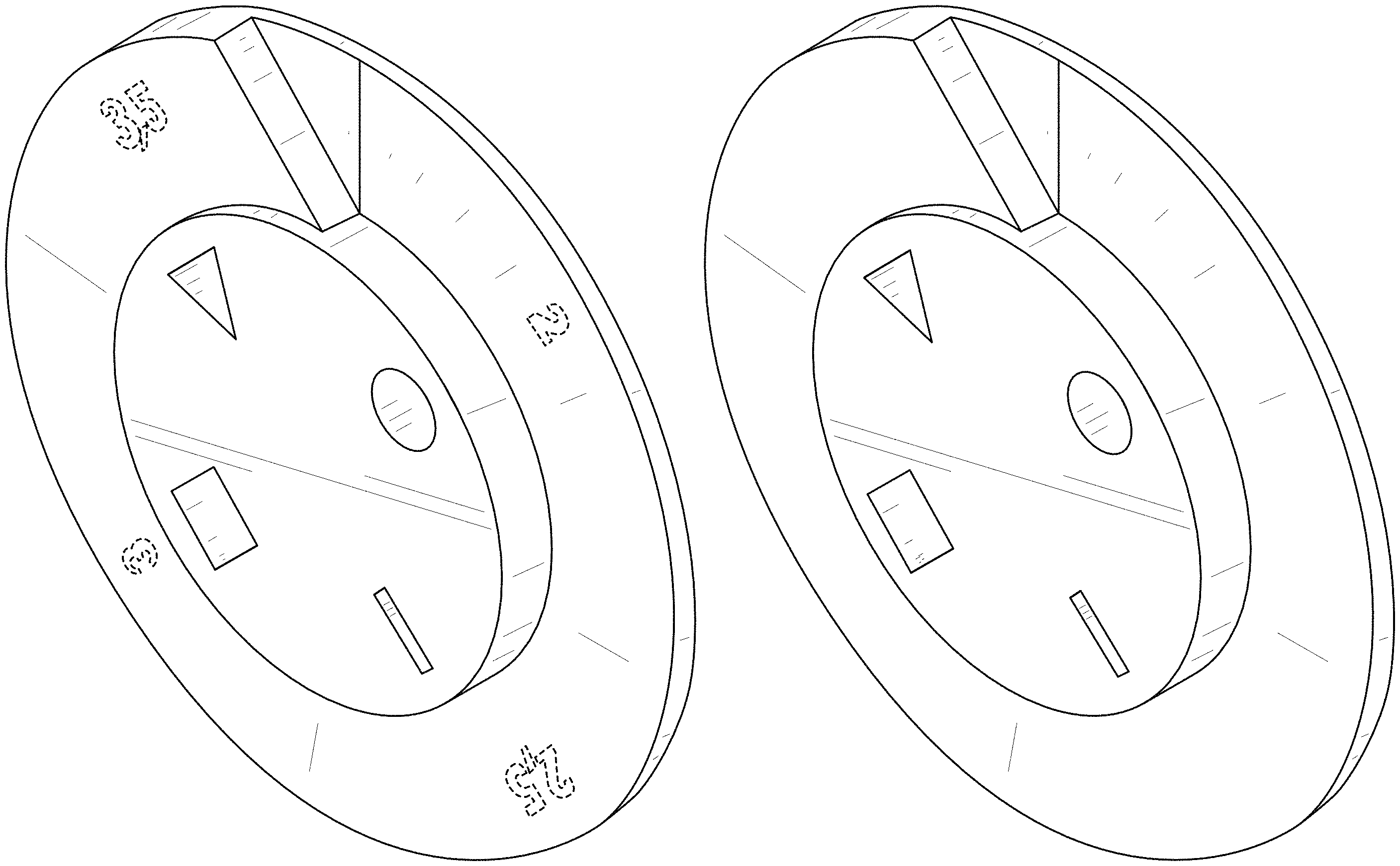
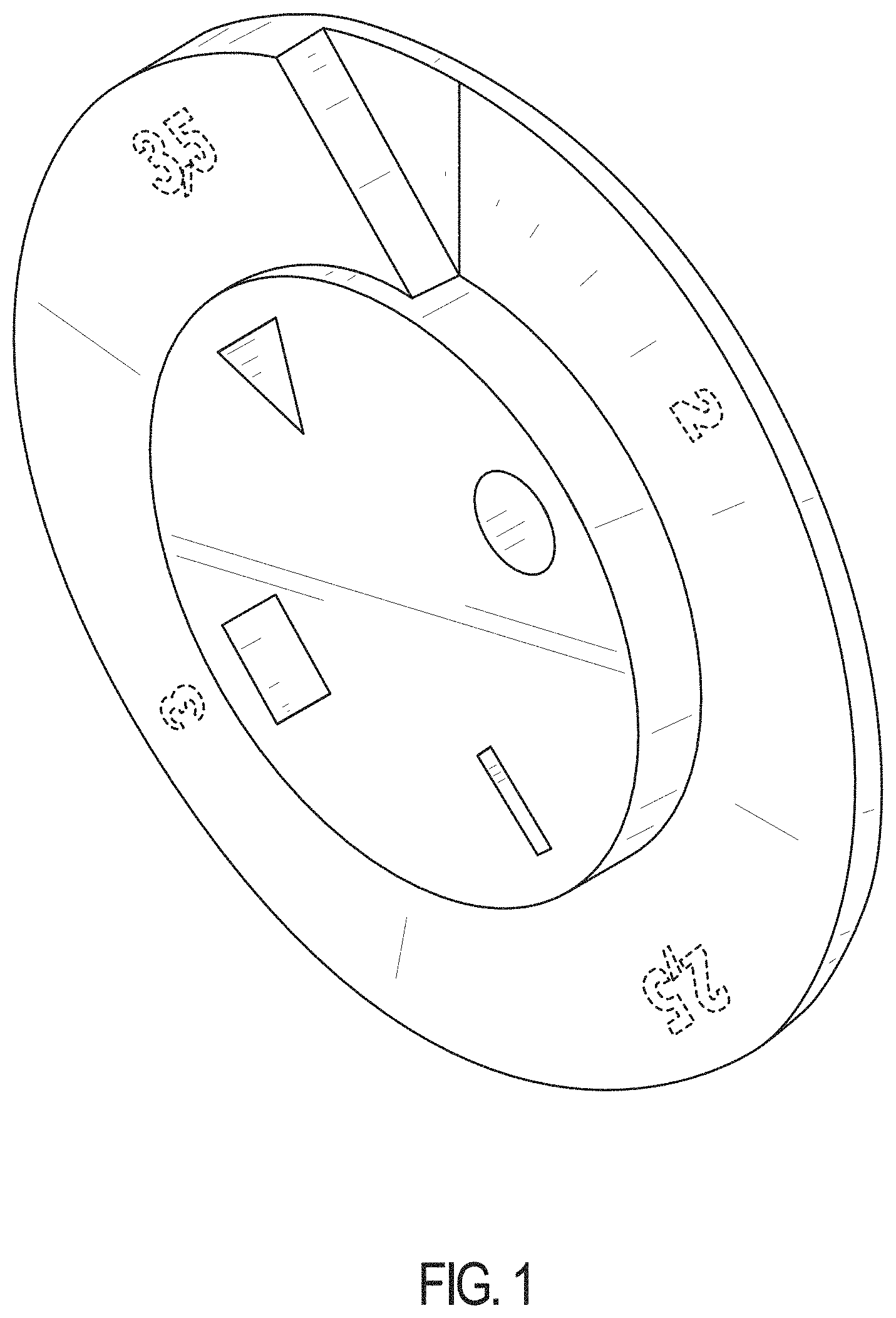
CLAIM The ornamental design for the tile spacer, as shown and described herein.
| Inventors: | Schluter; Werner (Iserlohn, DE) | ||||||||||
|---|---|---|---|---|---|---|---|---|---|---|---|
| Applicant: |
|
||||||||||
| Assignee: | Schluter Systems L.P.
(Plattsburgh, NY) |
||||||||||
| Appl. No.: | D/641,123 | ||||||||||
| Filed: | March 20, 2018 |
Foreign Application Priority Data
| Oct 5, 2017 [EP] | 004386787 | |||
| Current U.S. Class: | D8/354 |
| Current International Class: | 0805 |
| Field of Search: | ;D8/354,376,16,17,19,37,47,71,89,363,373,377,390,391,404 ;D10/61,64 ;D21/484,507,345,386 |
References Cited [Referenced By]
U.S. Patent Documents
| D330520 | October 1992 | Meadows |
| 5288534 | February 1994 | Tavshanjian |
| 5444921 | August 1995 | Milina |
| D373070 | August 1996 | Kriegstein |
| D493700 | August 2004 | O'Neill |
| 7257926 | August 2007 | Kirby |
| D616725 | June 2010 | Burns |
| D631326 | January 2011 | Burns |
| 8082714 | December 2011 | Burns |
| 8181409 | May 2012 | Jones |
| 9562365 | February 2017 | Bucsa |
| D829080 | September 2018 | Hill |
| D830161 | October 2018 | Russo |
Assistant Examiner: Blackwell, II; Harold E
Attorney, Agent or Firm: Thorpe North & Western, LLP
Description
FIG. 1 is a perspective view of my tile spacer in accordance with my invention;
FIG. 2 is a top view thereof;
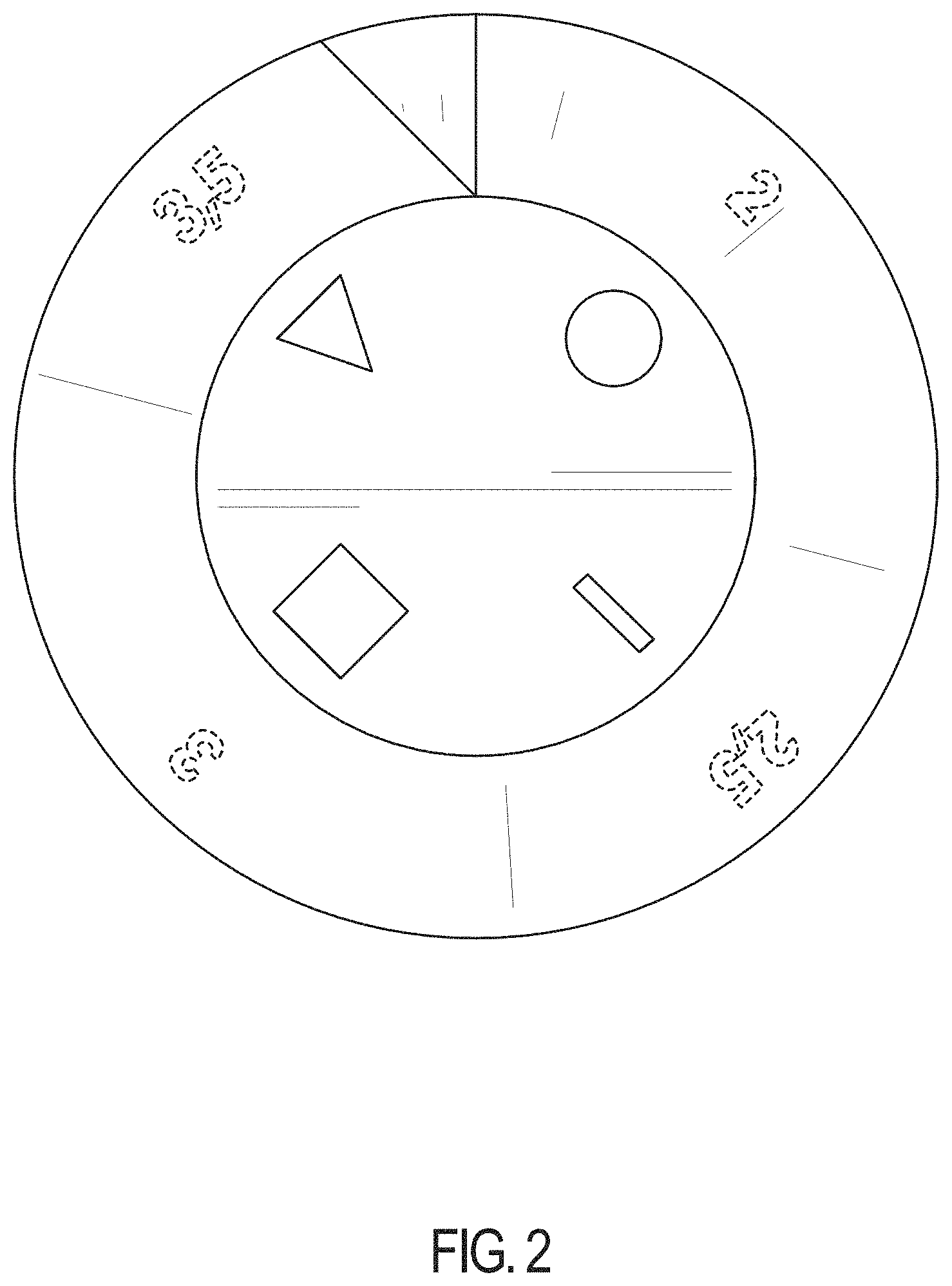
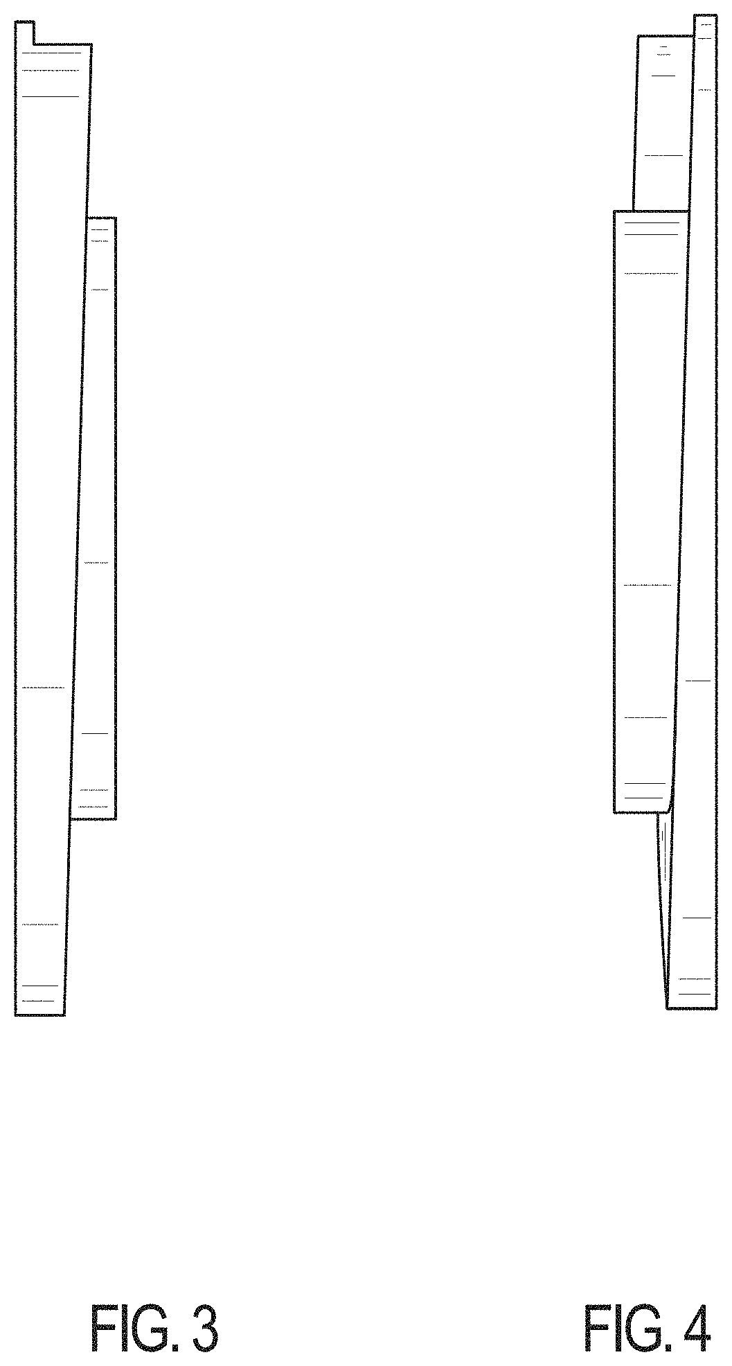
FIG. 3 is a side view thereof;
FIG. 4 is a side view opposing that of FIG. 3;
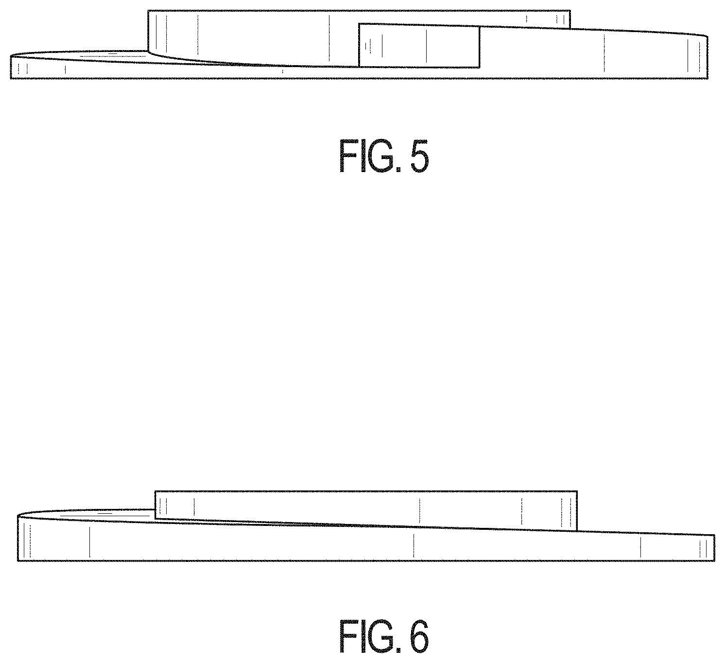
FIG. 5 is another side view thereof;
FIG. 6 is a side view opposing that of FIG. 5;
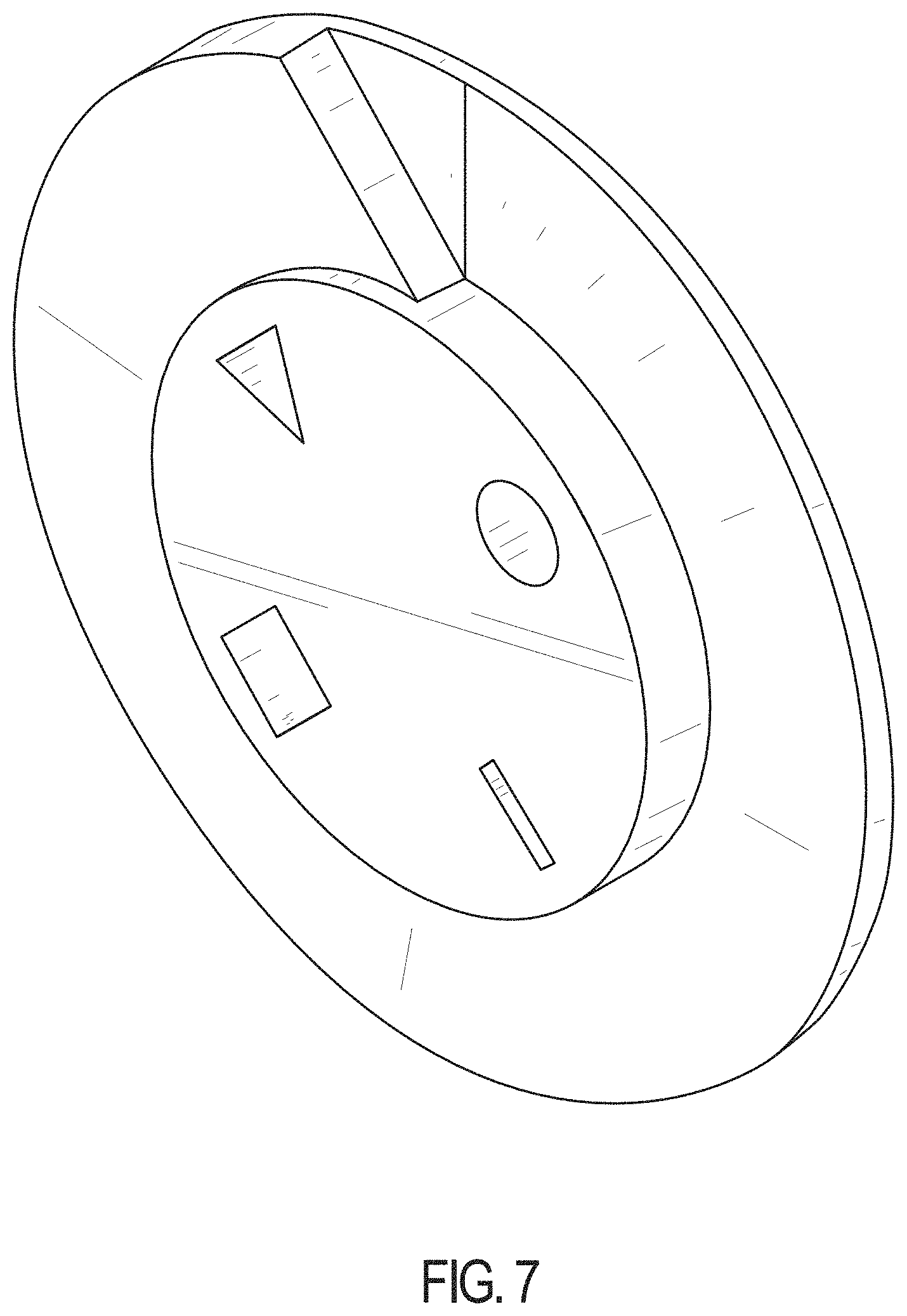
FIG. 7 is a perspective view of my tile spacer in accordance with another embodiment thereof;
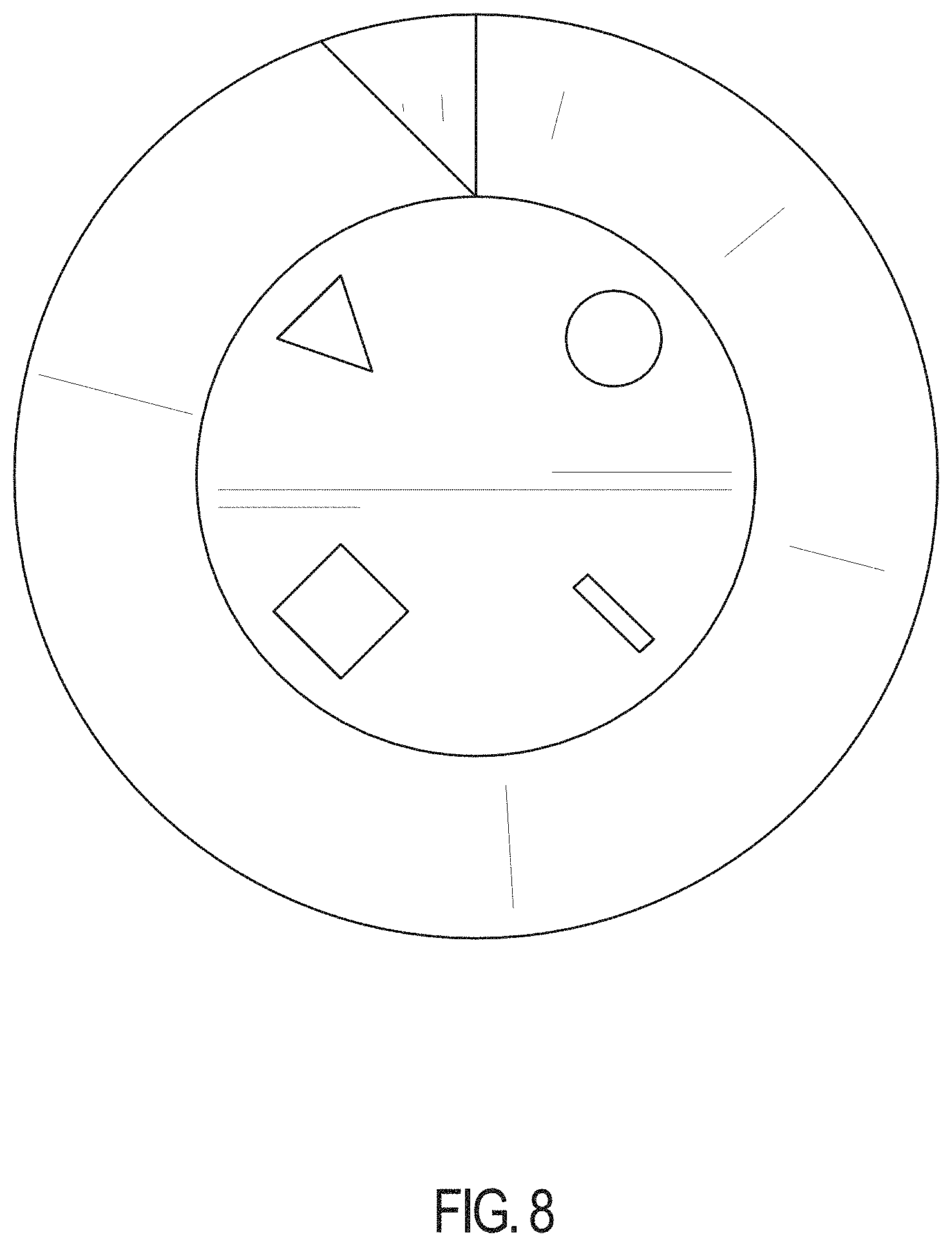
FIG. 8 is a top view thereof;
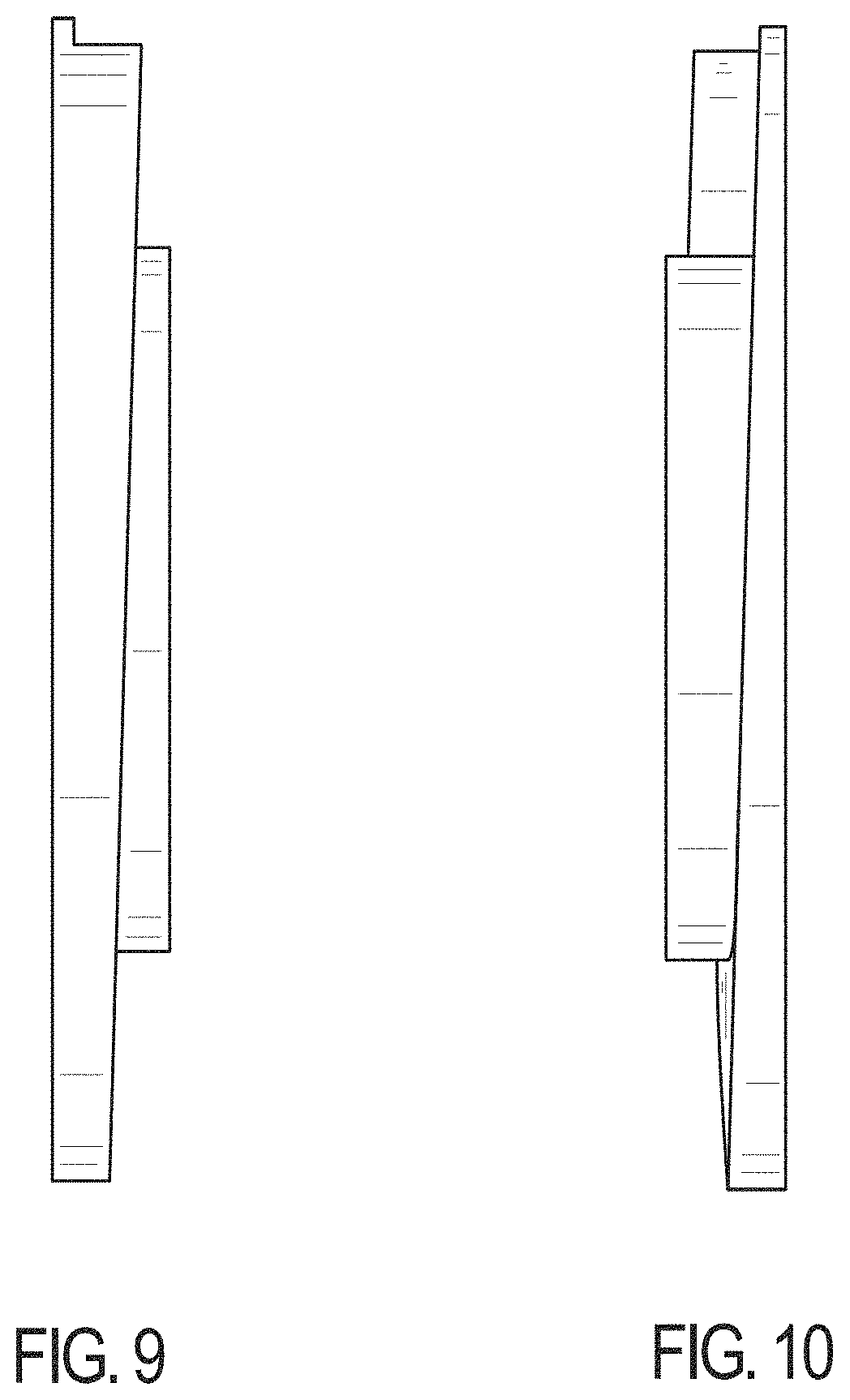
FIG. 9 is a side view thereof;
FIG. 10 is a side view opposing that of FIG. 9;
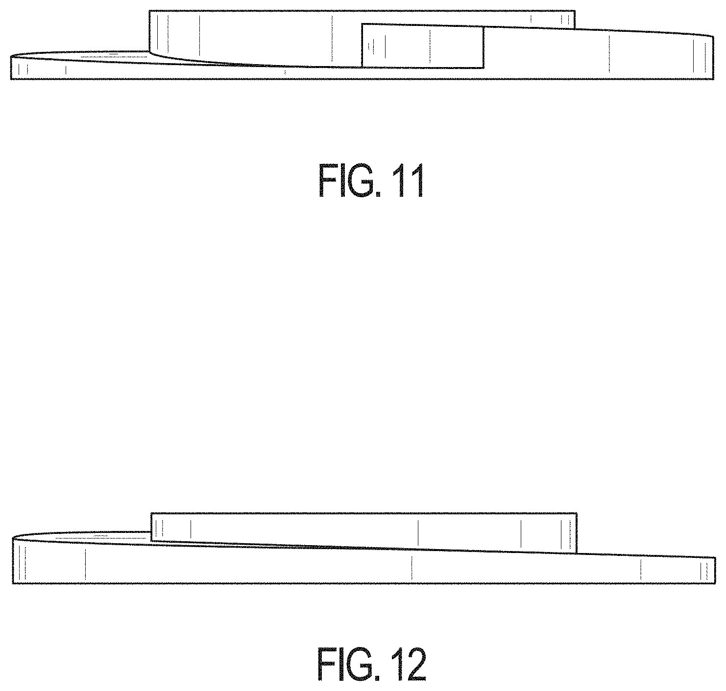
FIG. 11 is another side view thereof; and,
FIG. 12 is a side view opposing that of FIG. 11.
The broken line portions of the figure drawings are included to show portions of the article that form no part of the claimed design.
* * * * *
D00000
D00001
D00002
D00003
D00004
D00005
D00006
D00007
D00008
XML
uspto.report is an independent third-party trademark research tool that is not affiliated, endorsed, or sponsored by the United States Patent and Trademark Office (USPTO) or any other governmental organization. The information provided by uspto.report is based on publicly available data at the time of writing and is intended for informational purposes only.
While we strive to provide accurate and up-to-date information, we do not guarantee the accuracy, completeness, reliability, or suitability of the information displayed on this site. The use of this site is at your own risk. Any reliance you place on such information is therefore strictly at your own risk.
All official trademark data, including owner information, should be verified by visiting the official USPTO website at www.uspto.gov. This site is not intended to replace professional legal advice and should not be used as a substitute for consulting with a legal professional who is knowledgeable about trademark law.