Projector
Tanaka , et al.
U.S. patent number D878,453 [Application Number D/675,008] was granted by the patent office on 2020-03-17 for projector. This patent grant is currently assigned to FUJIFILM Corporation. The grantee listed for this patent is FUJIFILM Corporation. Invention is credited to Kunihiko Tanaka, Koji Yoshida.


View All Diagrams
| United States Patent | D878,453 |
| Tanaka , et al. | March 17, 2020 |
Projector
Claims
CLAIM The ornamental design for a projector, as shown and described.
| Inventors: | Tanaka; Kunihiko (Saitama, JP), Yoshida; Koji (Saitama, JP) | ||||||||||
|---|---|---|---|---|---|---|---|---|---|---|---|
| Applicant: |
|
||||||||||
| Assignee: | FUJIFILM Corporation (Tokyo,
JP) |
||||||||||
| Appl. No.: | D/675,008 | ||||||||||
| Filed: | December 27, 2018 |
Foreign Application Priority Data
| Jul 13, 2018 [JP] | 2018-015526 | |||
| Jul 13, 2018 [JP] | 2018-015527 | |||
| Current U.S. Class: | D16/235 |
| Current International Class: | 1602 |
| Field of Search: | ;D16/221,225,229-231,234-235,217,219 ;D21/514 ;353/101,119,122 |
References Cited [Referenced By]
U.S. Patent Documents
| D849121 | May 2019 | Ito |
| D867431 | November 2019 | Yoshida |
| 1611951 | Nov 2018 | JP | |||
| 1613727 | Nov 2018 | JP | |||
| 1618897 | Nov 2018 | JP | |||
Other References
|
A Notification issued by the Japan Patent Office dated Jan. 31, 2019, which corresponds to Japanese Design Application No. 2018-015526 and is related to Design U.S. Appl. No. 29/675,008. cited by applicant . A Notification issued by the Japan Patent Office dated Jan. 31, 2019, which corresponds to Japanese Design Application No. 2018-015527 and is related to Design U.S. Appl. No. 29/675,008. cited by applicant. |
Primary Examiner: Laymon; Wan
Attorney, Agent or Firm: Studebaker & Brackett PC
Description
FIG. 1 is a top left perspective view of a projector showing a first embodiment of our new design;
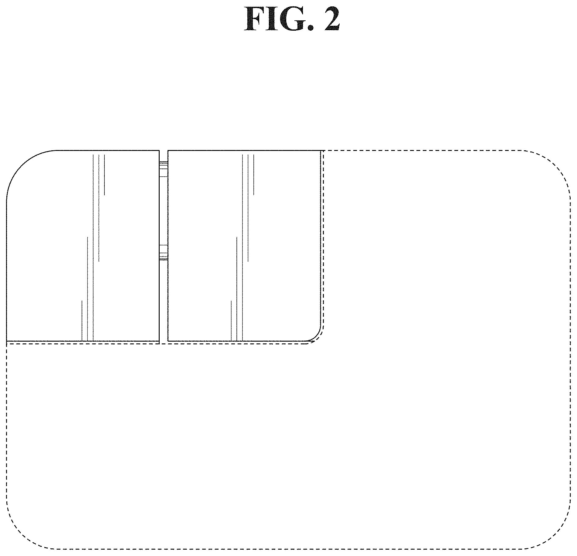
FIG. 2 is a front view thereof;
FIG. 3 is a rear view thereof;
FIG. 4 is a top plan view thereof;
FIG. 5 is a bottom plan view thereof;
FIG. 6 is a right side view thereof;
FIG. 7 is a left side view thereof;
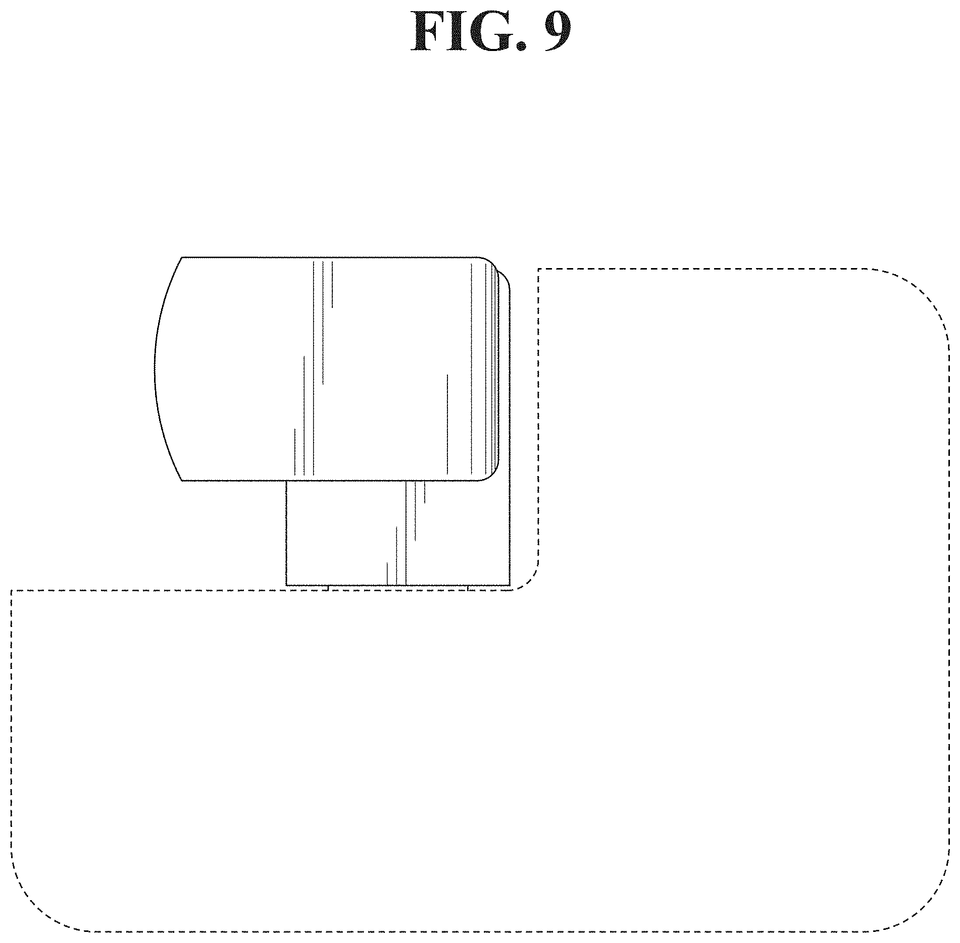
FIG. 8 is a top left perspective view of the projector showing the first embodiment, with a lens directed to a first direction;
FIG. 9 is a front view thereof;
FIG. 10 is a rear view thereof;
FIG. 11 is a top plan view thereof;
FIG. 12 is a bottom plan view thereof;
FIG. 13 is a right side view thereof;
FIG. 14 is a left side view thereof;
FIG. 15 is a top left perspective view of the projector showing the first embodiment, with the lens directed to a second direction;
FIG. 16 is a top left perspective view of the projector showing the first embodiment, with the lens directed to a third direction;
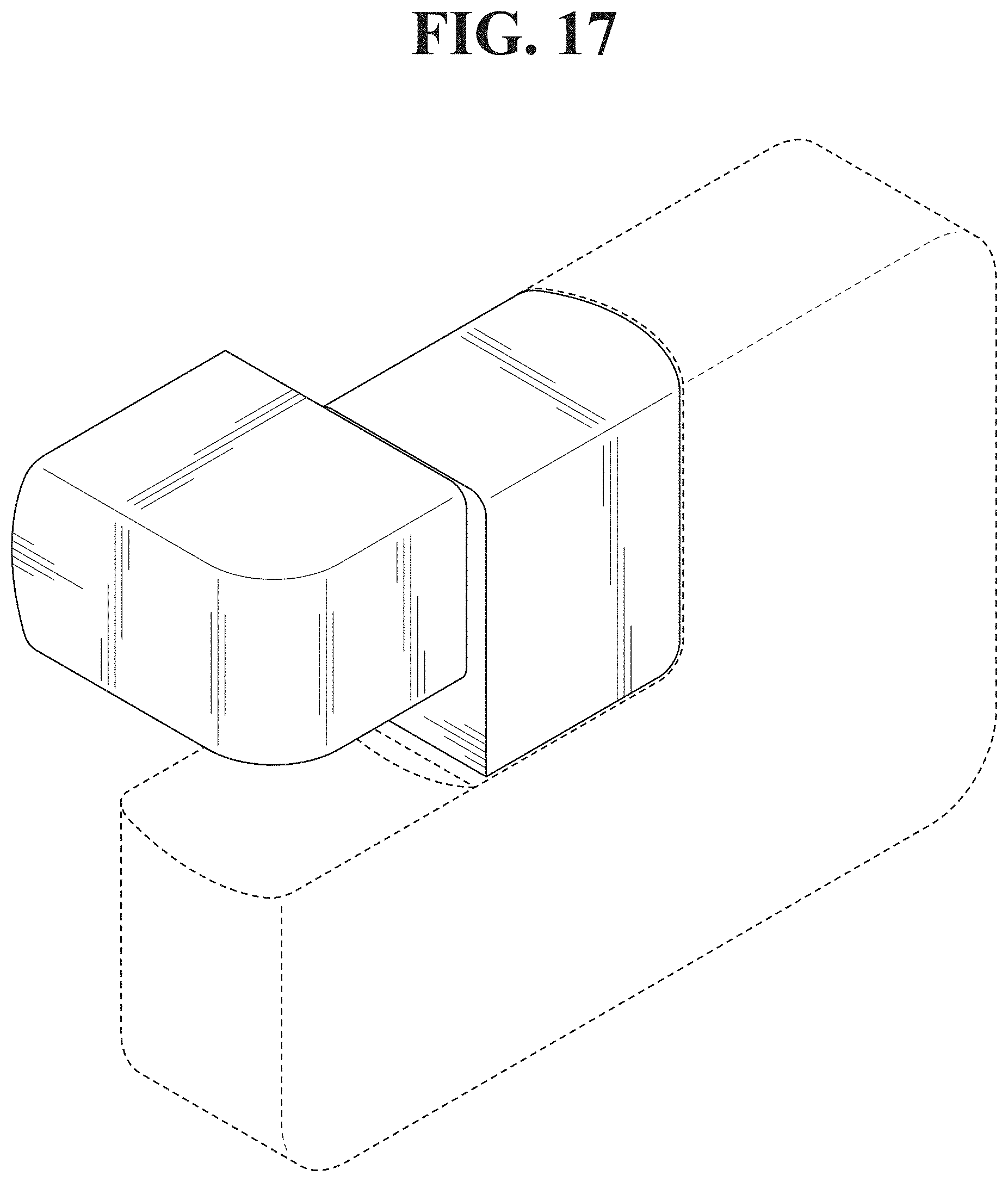
FIG. 17 is a top left perspective view of the projector showing the first embodiment, with the lens directed to a fourth direction;
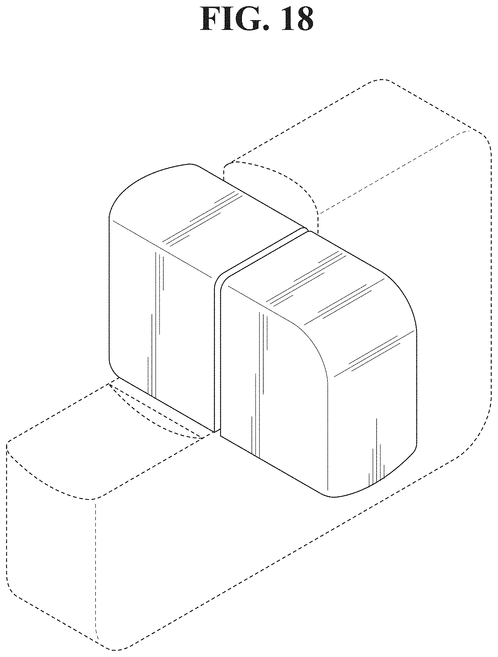
FIG. 18 is a top left perspective view of the projector showing the first embodiment, with the lens directed to a fifth direction;
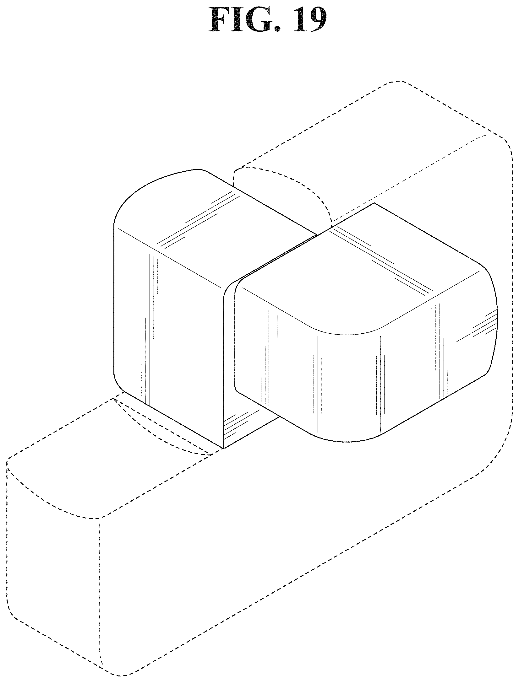
FIG. 19 is a top left perspective view of the projector showing the first embodiment, with the lens directed to a sixth direction;
FIG. 20 is a top left perspective view of the projector showing the first embodiment, with the lens directed to a seventh direction;
FIG. 21 is a top left perspective view of the projector showing the first embodiment, with the lens directed to an eighth direction;
FIG. 22 is a top left perspective view of the projector showing the first embodiment, with the lens directed to a ninth direction;
FIG. 23 is a top left perspective view of the projector showing the first embodiment, with the lens directed to a tenth direction;
FIG. 24 is a top left perspective view of the projector showing the first embodiment, with the lens directed to an eleventh direction;
FIG. 25 is a top left perspective view of a projector showing a second embodiment of our new design;
FIG. 26 is a front view thereof;
FIG. 27 is a rear view thereof;
FIG. 28 is a top plan view thereof;
FIG. 29 is a bottom plan view thereof;
FIG. 30 is a right side view thereof;
FIG. 31 is a left side view thereof;
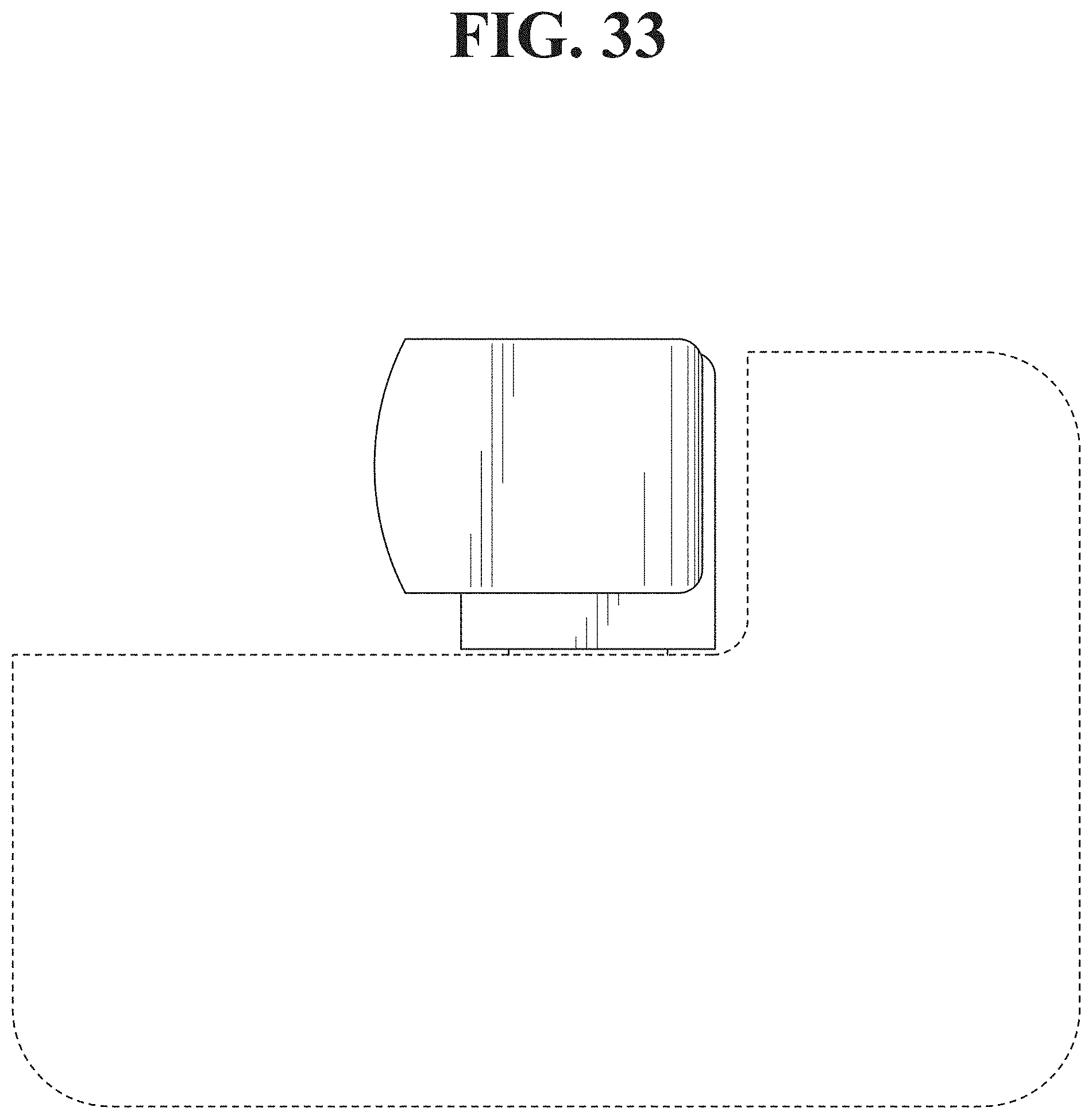
FIG. 32 is a top left perspective view of the projector showing the second embodiment, with a lens directed to a first direction;
FIG. 33 is a front view thereof;
FIG. 34 is a rear view thereof;
FIG. 35 is a top plan view thereof;
FIG. 36 is a bottom plan view thereof;
FIG. 37 is a right side view thereof;
FIG. 38 is a left side view thereof;
FIG. 39 is a top left perspective view of the projector showing the second embodiment, with the lens directed to a second direction;
FIG. 40 is a top left perspective view of the projector showing the second embodiment, with the lens directed to a third direction;
FIG. 41 is a top left perspective view of the projector showing the second embodiment, with the lens directed to a fourth direction;
FIG. 42 is a top left perspective view of the projector showing the second embodiment, with the lens directed to a fifth direction;
FIG. 43 is a top left perspective view of the projector showing the second embodiment, with the lens directed to a sixth direction;
FIG. 44 is a top left perspective view of the projector showing the second embodiment, with the lens directed to a seventh direction;
FIG. 45 is a top left perspective view of the projector showing the second embodiment, with the lens directed to an eighth direction;
FIG. 46 is a top left perspective view of the projector showing the second embodiment, with the lens directed to a ninth direction;
FIG. 47 is a top left perspective view of the projector showing the second embodiment, with the lens directed to a tenth direction; and,
FIG. 48 is a top left perspective view of the projector showing the second embodiment, with the lens directed to an eleventh direction.
The broken lines illustrate portions of the projector and form no part of the claimed design.
The design of a lens of the projector as the lens transitions from any one of the first to the eleventh positions to another of the first to the eleventh positions forms no part of the claimed design.
* * * * *
D00000
D00001
D00002
D00003
D00004
D00005
D00006
D00007
D00008
D00009
D00010
D00011
D00012

D00013

D00014

D00015
D00016
D00017
D00018

D00019

D00020

D00021

D00022

D00023

D00024

D00025

D00026

D00027

D00028

D00029

D00030
D00031

D00032

D00033

D00034

D00035

D00036

D00037

D00038

D00039

D00040

D00041

D00042

D00043

D00044

XML
uspto.report is an independent third-party trademark research tool that is not affiliated, endorsed, or sponsored by the United States Patent and Trademark Office (USPTO) or any other governmental organization. The information provided by uspto.report is based on publicly available data at the time of writing and is intended for informational purposes only.
While we strive to provide accurate and up-to-date information, we do not guarantee the accuracy, completeness, reliability, or suitability of the information displayed on this site. The use of this site is at your own risk. Any reliance you place on such information is therefore strictly at your own risk.
All official trademark data, including owner information, should be verified by visiting the official USPTO website at www.uspto.gov. This site is not intended to replace professional legal advice and should not be used as a substitute for consulting with a legal professional who is knowledgeable about trademark law.