Veneer block
Lindberg , et al.
U.S. patent number D877,936 [Application Number D/578,994] was granted by the patent office on 2020-03-10 for veneer block. This patent grant is currently assigned to E.P. Henry Corporation. The grantee listed for this patent is E.P. Henry Corporation. Invention is credited to John J. Lindberg, Eric Y. Long, John E. Ravelli.
View All Diagrams
| United States Patent | D877,936 |
| Lindberg , et al. | March 10, 2020 |
Veneer block
Claims
CLAIM We claim the ornamental design for a veneer block, as shown and described.
| Inventors: | Lindberg; John J. (Pottstown, PA), Ravelli; John E. (Dorothy, NJ), Long; Eric Y. (Sewell, NJ) | ||||||||||
|---|---|---|---|---|---|---|---|---|---|---|---|
| Applicant: |
|
||||||||||
| Assignee: | E.P. Henry Corporation
(Woodbury, NJ) |
||||||||||
| Appl. No.: | D/578,994 | ||||||||||
| Filed: | September 27, 2016 |
Related U.S. Patent Documents
| Application Number | Filing Date | Patent Number | Issue Date | ||
|---|---|---|---|---|---|
| 29502826 | Sep 19, 2014 | D768876 | |||
| Current U.S. Class: | D25/113 |
| Current International Class: | 2501 |
| Field of Search: | ;D25/113-118,138,152-162,164,199 |
References Cited [Referenced By]
U.S. Patent Documents
| 2002311 | May 1935 | David |
| 2238787 | April 1941 | Aberson |
| 2482556 | September 1949 | Petras |
| 3290849 | December 1966 | Wright |
| 4590726 | May 1986 | Salazar |
| 5465544 | November 1995 | Ghahary |
| 6000183 | December 1999 | Newman |
| 6062772 | May 2000 | Perkins |
| D466619 | December 2002 | Britton |
| D468449 | January 2003 | Britton |
| D493545 | July 2004 | Lancia |
| D530831 | October 2006 | Mugge et al. |
| D584423 | January 2009 | Mugge et al. |
| 7490444 | February 2009 | Nowack |
| 7637737 | December 2009 | Furner et al. |
| D611164 | March 2010 | Mugge et al. |
| D639455 | June 2011 | Mugge et al. |
| 7976963 | July 2011 | Olson, III et al. |
| D644744 | September 2011 | Meadows |
| D644745 | September 2011 | Meadows |
| D644746 | September 2011 | Meadows |
| D644747 | September 2011 | Meadows |
| D644748 | September 2011 | Meadows |
| D644749 | September 2011 | Meadows |
| D645165 | September 2011 | Wolter et al. |
| D646402 | October 2011 | Mugge |
| D674512 | January 2013 | Manthei |
| D679029 | March 2013 | Mugge et al. |
| D685923 | July 2013 | Mugge et al. |
| D690837 | October 2013 | Mugge et al. |
| D696425 | December 2013 | Mugge et al. |
| D698942 | February 2014 | Mugge et al. |
| D699866 | February 2014 | Mugge et al. |
| D703346 | April 2014 | Johnson et al. |
| 2011/0203211 | August 2011 | Metten |
| 147346 | Sep 2013 | CA | |||
| 2002/097773 | Apr 2002 | JP | |||
| WO 2012/059757 | May 2012 | WO | |||
Other References
|
Canadian Patent Application No. 161595: Examiner's Report dated Jan. 26, 2016, 1 page. cited by applicant. |
Primary Examiner: Doan; Anhdao
Attorney, Agent or Firm: BakerHostetler
Description
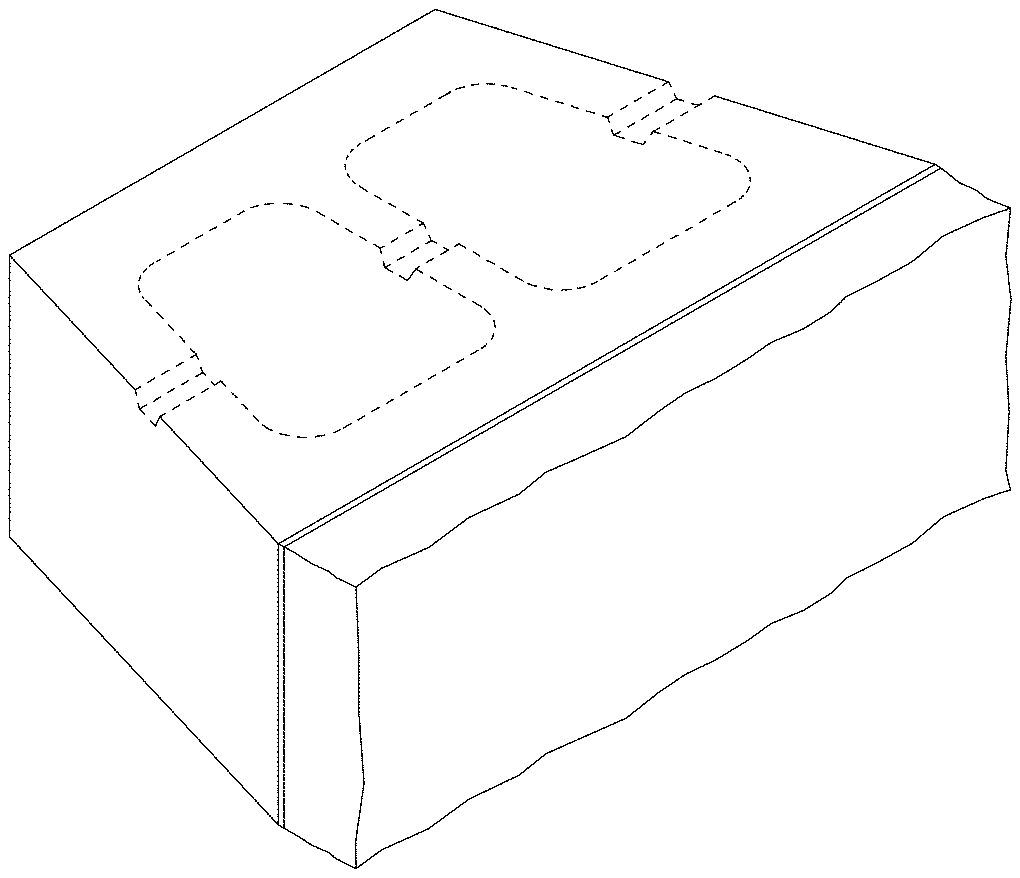
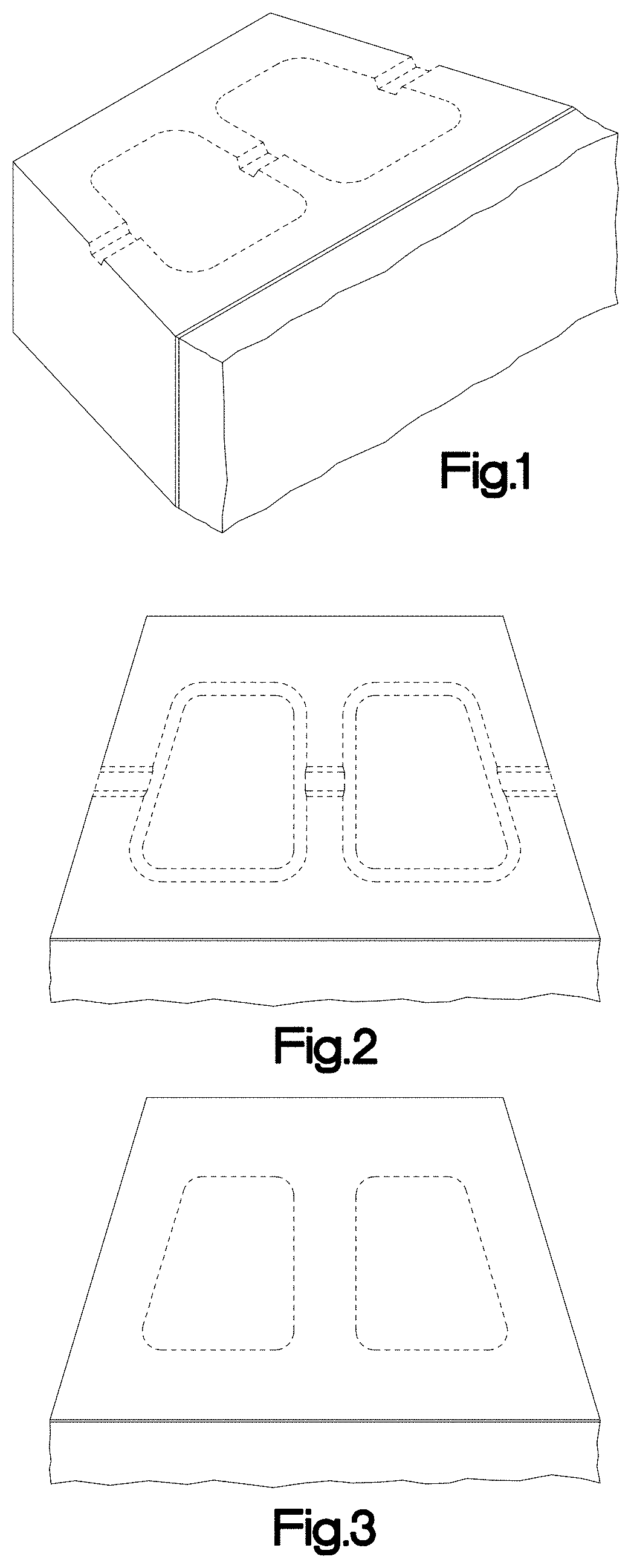
FIG. 1 is a top, left, front perspective view of one embodiment of a veneer block according to our design;
FIG. 2 is a top plan view of the veneer block illustrated in FIG. 1;
FIG. 3 is a bottom plan view of the veneer block illustrated in FIG. 1;
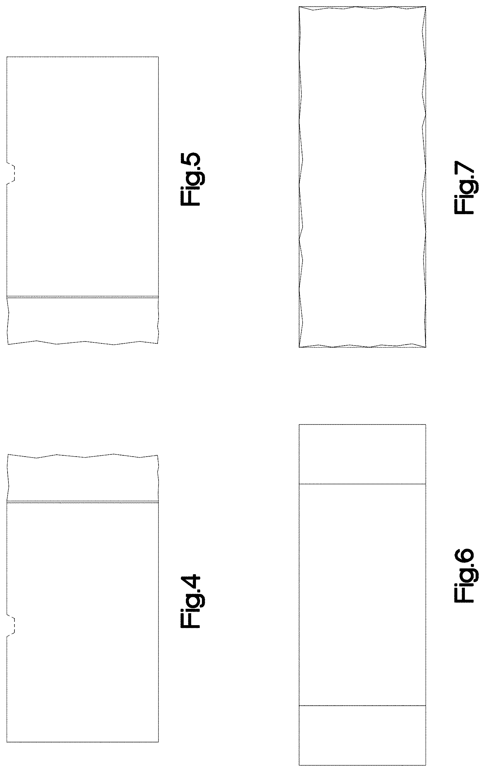
FIG. 4 is a left side elevation view of the veneer block illustrated in FIG. 1;
FIG. 5 is a right side elevation view of the veneer block illustrated in FIG. 1;
FIG. 6 is a rear elevation view of the veneer block illustrated in FIG. 1;
FIG. 7 is a front elevation view of the veneer block illustrated in FIG. 1;
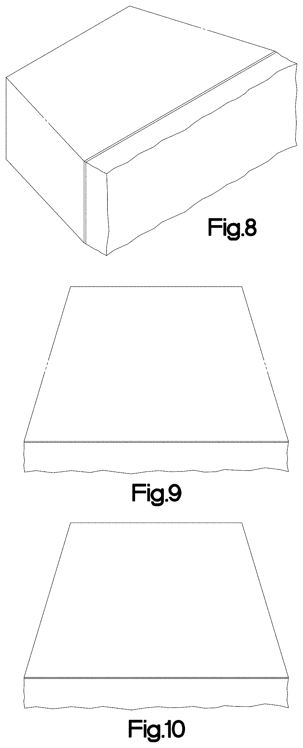
FIG. 8 is a top, left, front perspective view of another embodiment of the veneer block illustrated in FIG. 1;
FIG. 9 is a top plan view of the veneer block illustrated in FIG. 8;
FIG. 10 is a bottom plan view of the veneer block illustrated in FIG. 8;
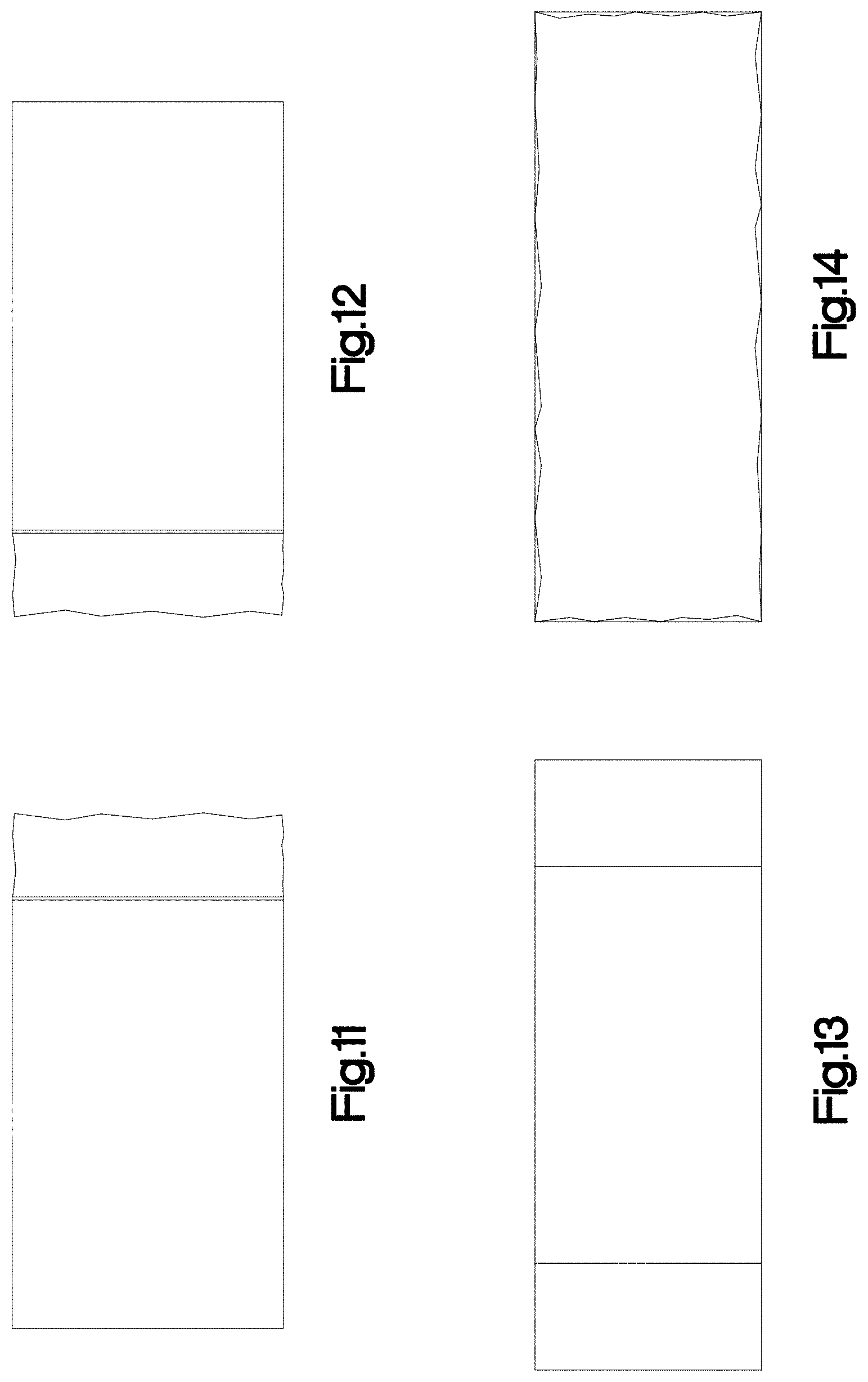
FIG. 11 is a left side elevation view of the veneer block illustrated in FIG. 8;
FIG. 12 is a right side elevation view of the veneer block illustrated in FIG. 8;
FIG. 13 is a rear elevation view of the veneer block illustrated in FIGS. 8; and
FIG. 14 is a front elevation view of the veneer block illustrated in FIG. 8.
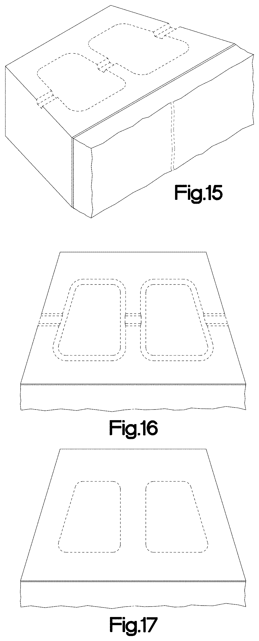
FIG. 15 is a top, left, front perspective view of another embodiment of the veneer block illustrated in FIG. 1;
FIG. 16 is a top plan view of the veneer block illustrated in FIG. 15;
FIG. 17 is a bottom plan view of the veneer block illustrated in FIG. 15;
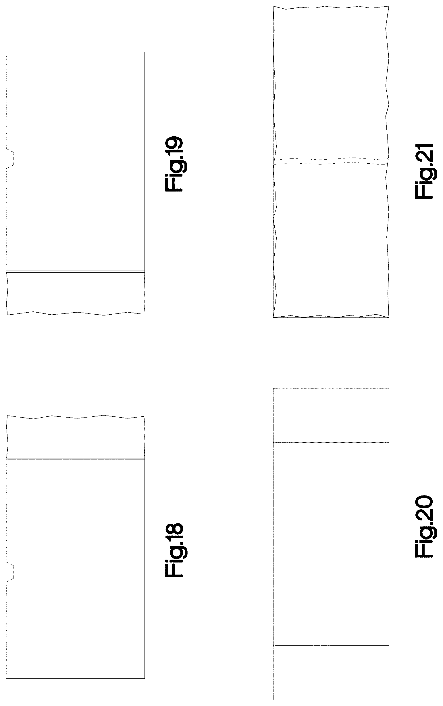
FIG. 18 is a left side elevation view of the veneer block illustrated in FIG. 15;
FIG. 19 is a right side elevation view of the veneer block illustrated in FIG. 15;
FIG. 20 is a rear elevation view of the veneer block illustrated in FIG. 15;
FIG. 21 is a front elevation view of the veneer block illustrated in FIG. 15;
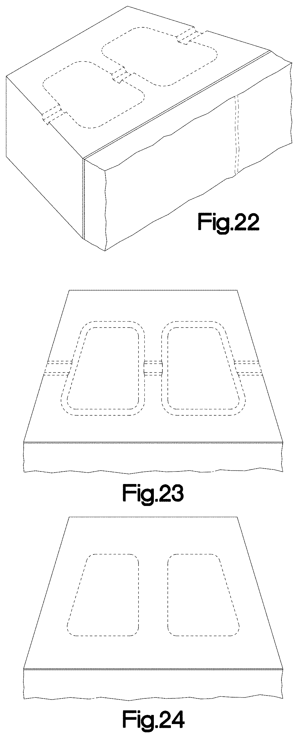
FIG. 22 is a top, left, front perspective view of another embodiment of the veneer block illustrated in FIG. 1;
FIG. 23 is a top plan view of the veneer block illustrated in FIG. 22;
FIG. 24 is a bottom plan view of the veneer block illustrated in FIG. 22;
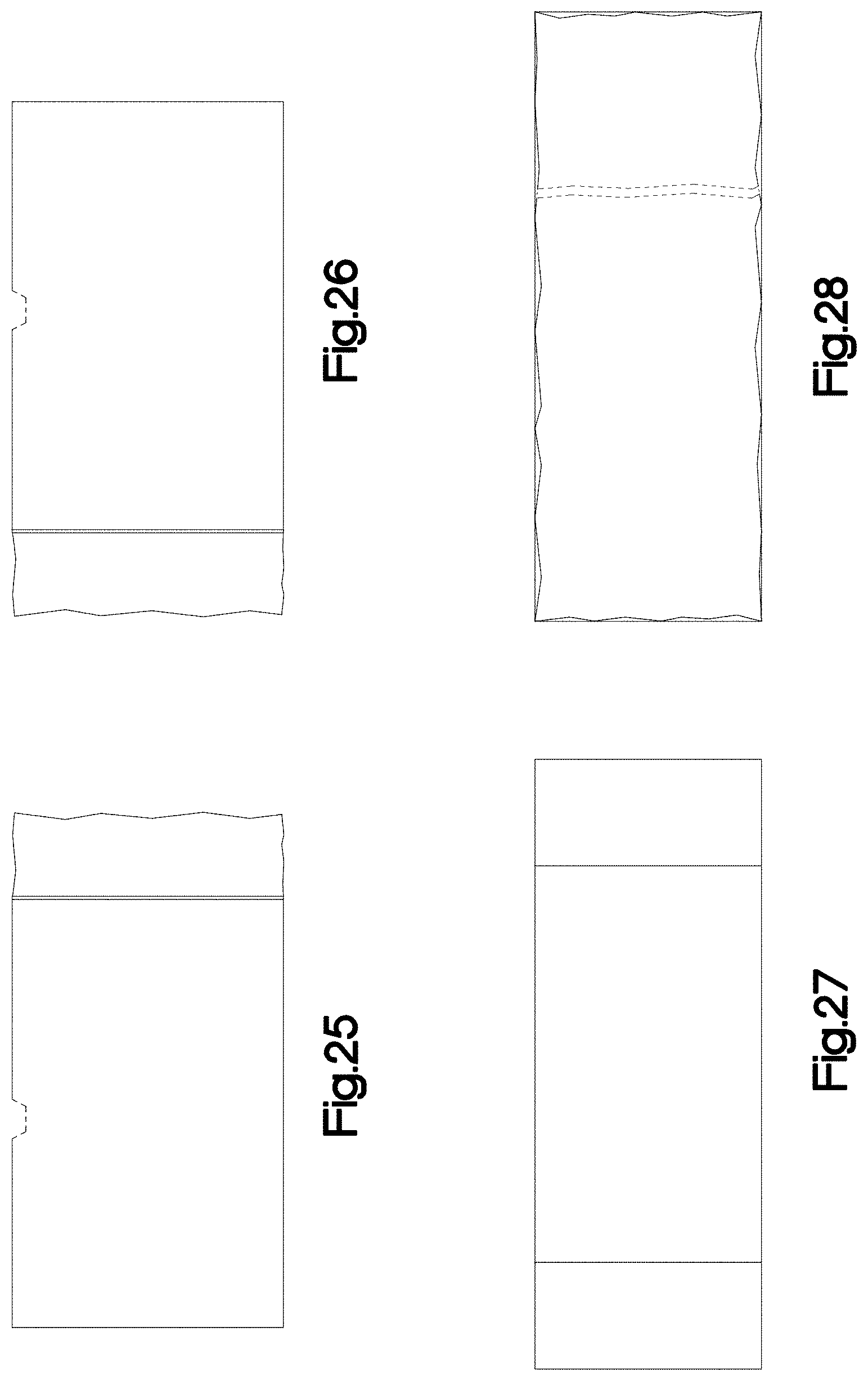
FIG. 25 is a left side elevation view of the veneer block illustrated in FIG. 22;
FIG. 26 is a right side elevation view of the veneer block illustrated in FIG. 22;
FIG. 27 is a rear elevation view of the veneer block illustrated in FIG. 22;
FIG. 28 is a front elevation view of the veneer block illustrated in FIG. 22;
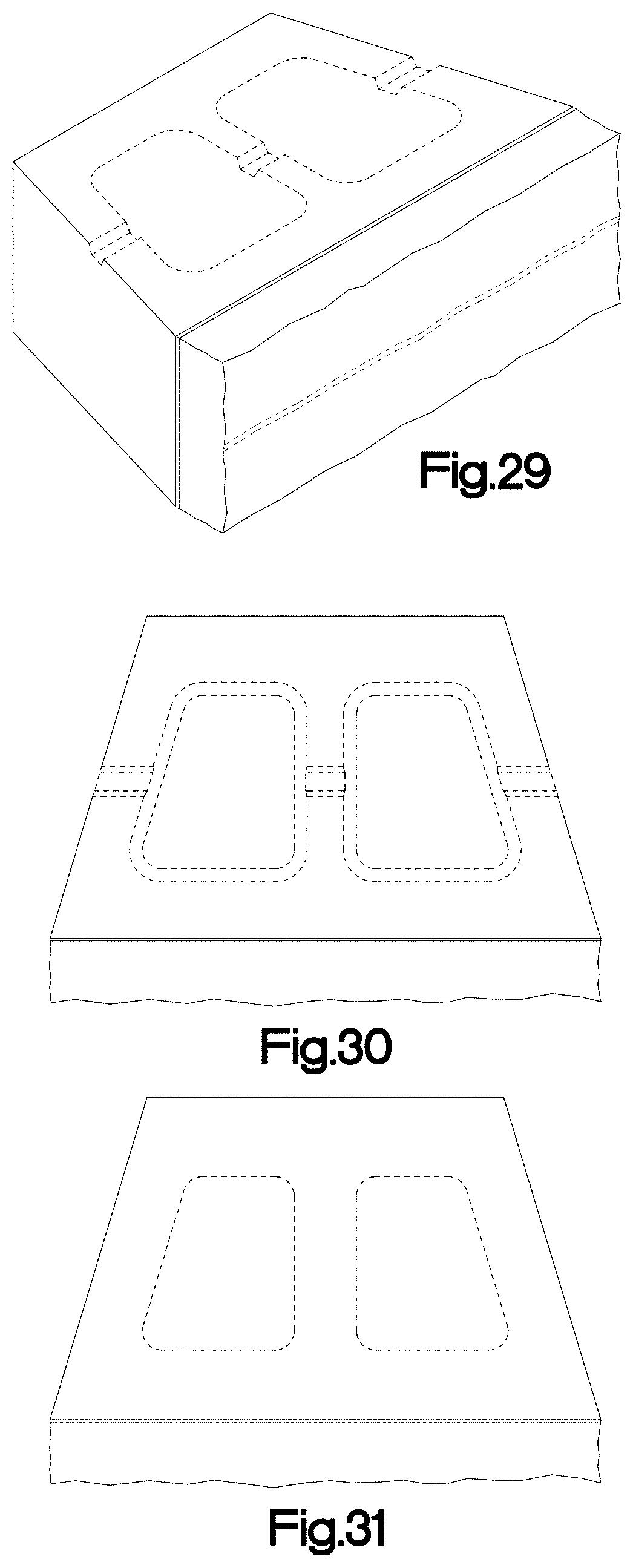
FIG. 29 is a top, left, front perspective view of another embodiment of the veneer block illustrated in FIG. 1;
FIG. 30 is a top plan view of the veneer block illustrated in FIG. 29;
FIG. 31 is a bottom plan view of the veneer block illustrated in FIG. 29;
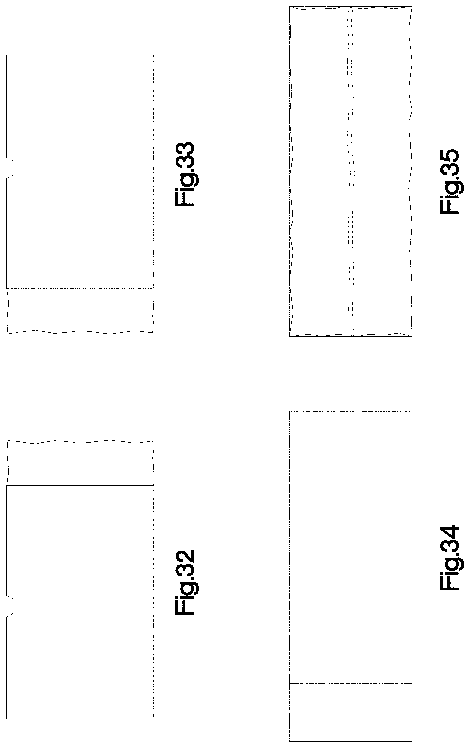
FIG. 32 is a left side elevation view of the veneer block illustrated in FIG. 29;
FIG. 33 is a right side elevation view of the veneer block illustrated in FIG. 29;
FIG. 34 is a rear elevation view of the veneer block illustrated in FIG. 29;
FIG. 35 is a front elevation view of the veneer block illustrated in FIG. 29;
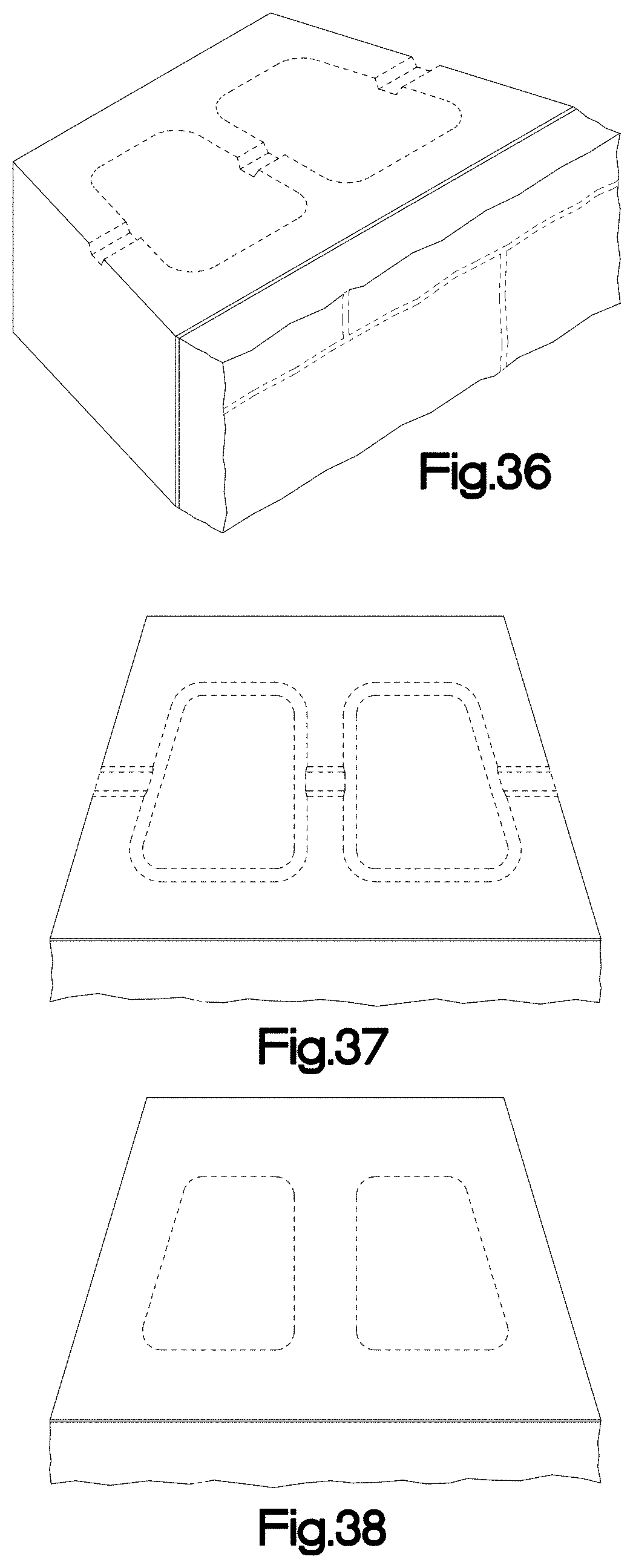
FIG. 36 is a top, left, front perspective view of another embodiment of the veneer block illustrated in FIG. 1;
FIG. 37 is a top plan view of the veneer block illustrated in FIG. 36;
FIG. 38 is a bottom plan view of the veneer block illustrated in FIG. 36;
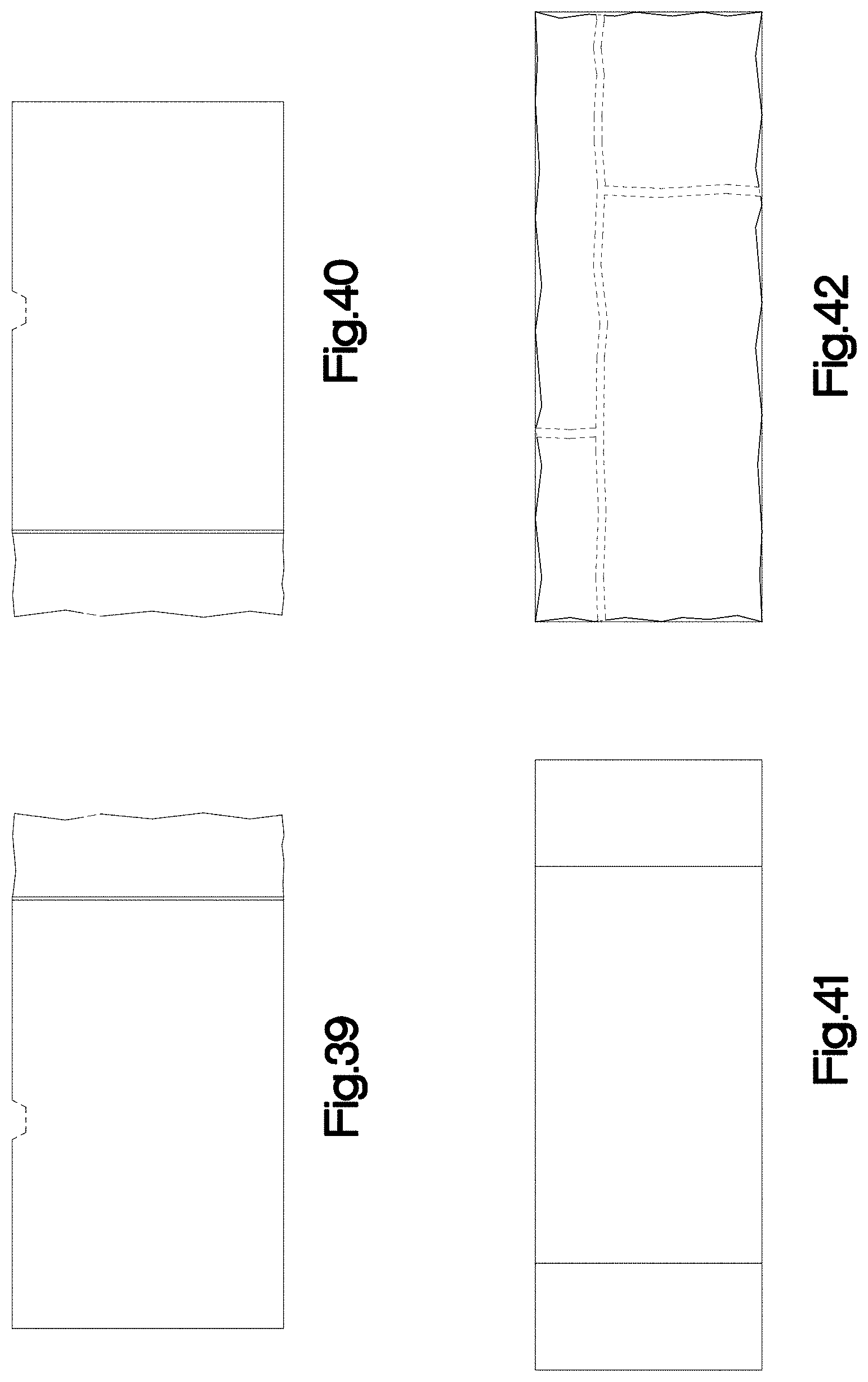
FIG. 39 is a left side elevation view of the veneer block illustrated in FIG. 36;
FIG. 40 is a right side elevation view of the veneer block illustrated in FIG. 36;
FIG. 41 is a rear elevation view of the veneer block illustrated in FIG. 36;
FIG. 42 is a front elevation view of the veneer block illustrated in FIG. 36;
FIG. 43 is a top, left, front perspective view of another embodiment of the veneer block illustrated in FIG. 1;
FIG. 44 is a top plan view of the veneer block illustrated in FIG. 43;
FIG. 45 is a bottom plan view of the veneer block illustrated in FIG. 43;
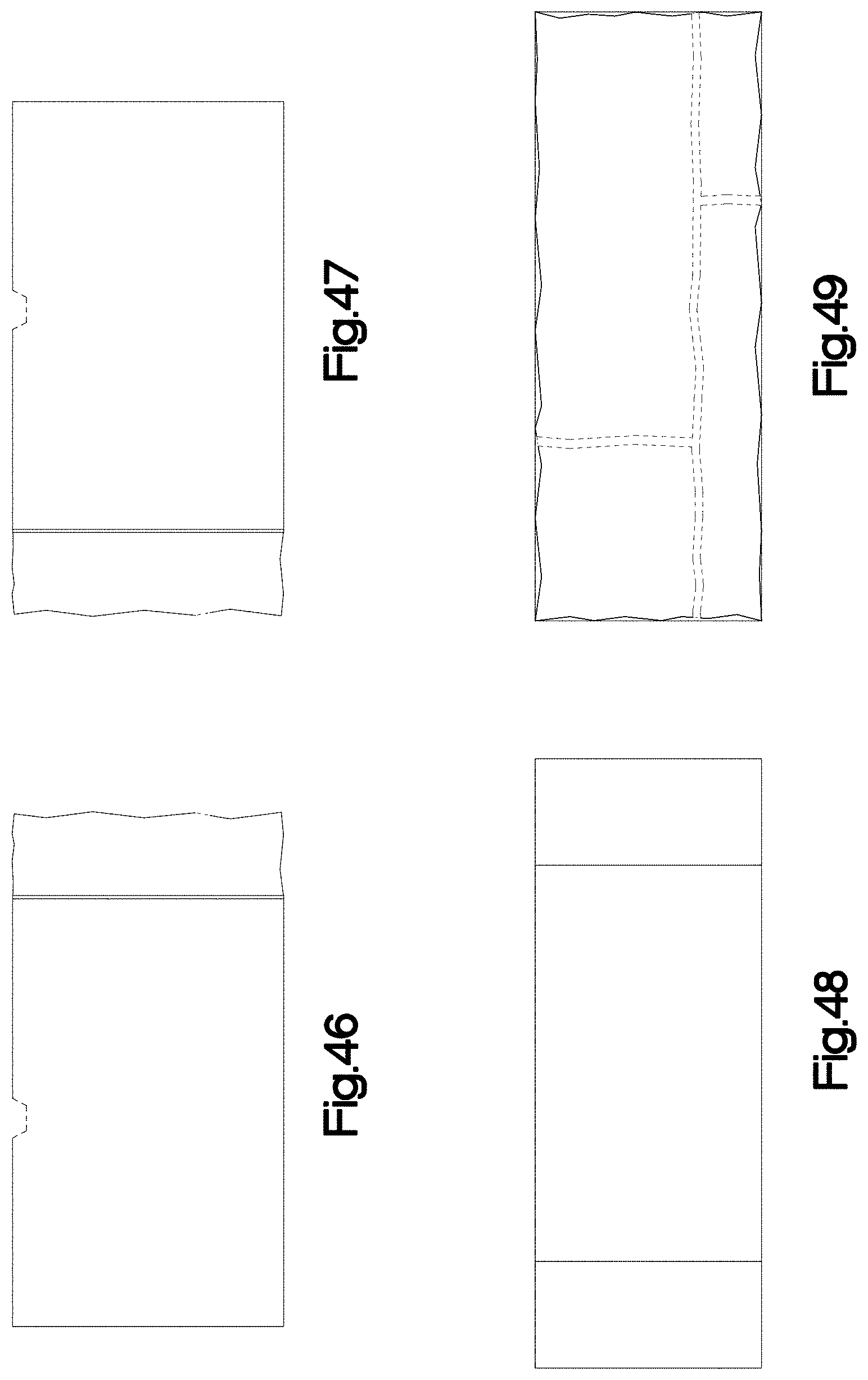
FIG. 46 is a left side elevation view of the veneer block illustrated in FIG. 43;
FIG. 47 is a right side elevation view of the veneer block illustrated in FIG. 43;
FIG. 48 is a rear elevation view of the veneer block illustrated in FIG. 43; and,
FIG. 49 is a front elevation view of the veneer block illustrated in FIG. 43.
It is understood that the claim is to the edges of the veneer block shown in solid lines in the drawings. The broken line portion of the drawings is included to show unclaimed subject matter only for the purpose of illustrating environment and forms no part of the claimed design.
* * * * *
D00000
D00001
D00002
D00003
D00004
D00005
D00006
D00007
D00008
D00009
D00010
D00011
D00012
D00013

D00014
XML
uspto.report is an independent third-party trademark research tool that is not affiliated, endorsed, or sponsored by the United States Patent and Trademark Office (USPTO) or any other governmental organization. The information provided by uspto.report is based on publicly available data at the time of writing and is intended for informational purposes only.
While we strive to provide accurate and up-to-date information, we do not guarantee the accuracy, completeness, reliability, or suitability of the information displayed on this site. The use of this site is at your own risk. Any reliance you place on such information is therefore strictly at your own risk.
All official trademark data, including owner information, should be verified by visiting the official USPTO website at www.uspto.gov. This site is not intended to replace professional legal advice and should not be used as a substitute for consulting with a legal professional who is knowledgeable about trademark law.