Box with securable tray
Sollie , et al.
U.S. patent number D877,614 [Application Number D/655,643] was granted by the patent office on 2020-03-10 for box with securable tray. This patent grant is currently assigned to Pratt Corrugated Holdings, Inc.. The grantee listed for this patent is Pratt Corrugated Holdings, Inc.. Invention is credited to Shifeng Chen, Paul Ott, Greg Sollie, Jamie Waltermire.


| United States Patent | D877,614 |
| Sollie , et al. | March 10, 2020 |
Box with securable tray
Claims
CLAIM We claim the ornamental design for a box with securable tray, as shown and described.
| Inventors: | Sollie; Greg (Sharpsburg, GA), Ott; Paul (Atlanta, GA), Waltermire; Jamie (Peachtree City, GA), Chen; Shifeng (Newport News, VA) | ||||||||||
|---|---|---|---|---|---|---|---|---|---|---|---|
| Applicant: |
|
||||||||||
| Assignee: | Pratt Corrugated Holdings, Inc.
(Conyers, GA) |
||||||||||
| Appl. No.: | D/655,643 | ||||||||||
| Filed: | July 5, 2018 |
| Current U.S. Class: | D9/432; D9/433 |
| Current International Class: | 0903 |
| Field of Search: | ;D9/414-423,424-429,430-433,434,456,457,711,713,721-722 ;D3/272-274,290,304,305,315 ;D20/10,22,27,40,42 |
References Cited [Referenced By]
U.S. Patent Documents
| 696928 | April 1902 | Beecher |
| 2537801 | January 1951 | Swatsick |
| 2618429 | November 1952 | Donnell |
| 2718996 | September 1955 | Jamieson |
| 2736486 | February 1956 | Rabby |
| 2822973 | February 1958 | Armstrong et al. |
| 3058643 | October 1962 | Wilson |
| 3303986 | February 1967 | Tanaka |
| 3438562 | April 1969 | Wright |
| 3782619 | January 1974 | Dittbenner |
| 4030600 | June 1977 | Heaps |
| 4089417 | May 1978 | Osborne |
| 4199832 | April 1980 | Glasscock |
| 4504497 | March 1985 | Kurth |
| 4717070 | January 1988 | Taub |
| 4927074 | May 1990 | Larue et al. |
| 4948033 | August 1990 | Halsell, II |
| D315098 | March 1991 | Hutcheson |
| D339062 | September 1993 | Williams |
| 5328042 | July 1994 | Heise |
| 5699959 | December 1997 | Huspeka |
| D398228 | September 1998 | Herbst |
| D398230 | September 1998 | Herbst |
| D424117 | May 2000 | Steinbeck |
| D643714 | August 2011 | Daley et al. |
| D664312 | July 2012 | Bizzle |
| D673368 | January 2013 | Scott |
| 8720736 | May 2014 | Boland |
| D740564 | October 2015 | Scott |
| D749944 | February 2016 | Kummerfeldt |
| 10106290 | October 2018 | Couture |
| D840806 | February 2019 | Bourke |
| D854830 | July 2019 | Criste |
| 2015/0353270 | December 2015 | Gaul |
| 2020/0010236 | January 2020 | Sollie et al. |
| 3517176 | Nov 1986 | DE | |||
| 19741540 | Mar 1999 | DE | |||
| 2449603 | Sep 1980 | FR | |||
Other References
|
Bankers Box SmoothMove Moving. [online] Published on Nov. 1, 2012. Retrieved Jul. 29, 2019 from URL: https://www.target.com/p/bankers-box-174-smoothmove-moving-storage-box-ex- tra-strength-large-18w-x-18d-x-24h-kraft/-/A-16942594. cited by examiner . Office Supply Hut; Article entitled: "Bankers Box Recycled Stor/File--Letter/Legal", located at <http://www.officesupplyhut.com/Products/Bankers-Box-Recycled-StorFile- andtrade----LetterLegal_FEL12770.aspx>, Accessed Feb. 22, 2018, 4 pgs. cited by applicant . Rajapack; Article entitled: "Cardboard cap and sleeve loading cases without pallets", located at <https://www.rajapack.co.uk/cardboard-boxes/export-boxes/cardboard-cap- -sleeve-loading-cases-without-pallets_PDT04683.html>, Accessed Feb. 22, 2018, 2 pgs. cited by applicant . The Custom Boxes; Article entitled: "Cardboard Boxes", located at <https://www.thecustomboxes.com/cardboard-boxes/>, Accessed on Feb. 22, 2018, 1 pg. cited by applicant . Sollie, Greg; Non-Final Office Action for U.S. Appl. No. 16/028,033, filed Jul. 5, 2018, dated Oct. 17, 2019, 15 pgs. cited by applicant. |
Primary Examiner: Koenig; Vy N
Attorney, Agent or Firm: Taylor English Duma LLP
Description
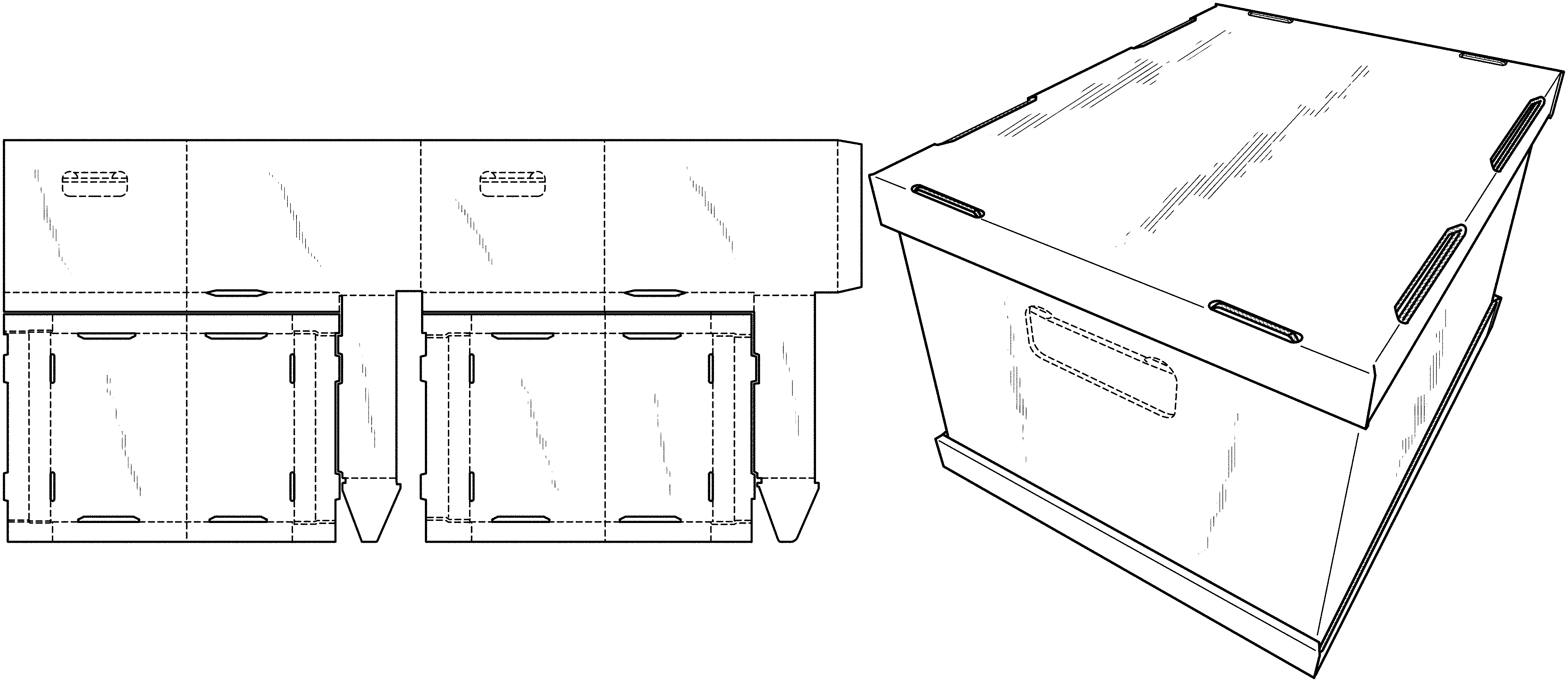
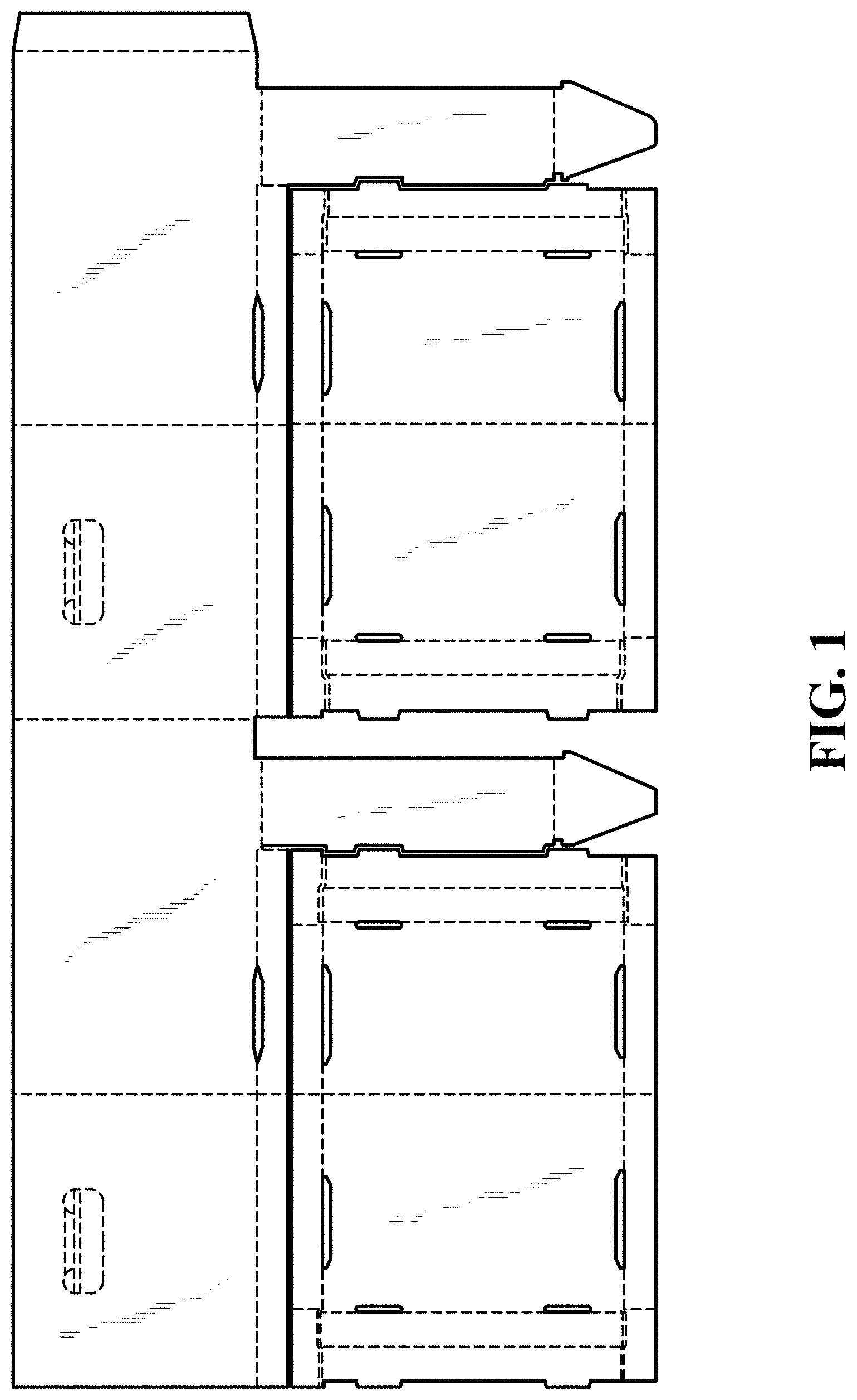
FIG. 1 is a top plan view of our new design for a box with securable tray, comprising a sidewall enclosure and a pair of trays in an unassembled blank configuration.
FIG. 2 is a top plan view of the sidewall enclosure in a blank configuration thereof, shown separately to show aspects of the design that may not be apparent in the other views.
FIG. 3 is a top plan view of one of the pair of trays in a blank configuration thereof, shown separately to show aspects of the design that may not be apparent in the other views, the other one of the pair of trays being substantially the same.
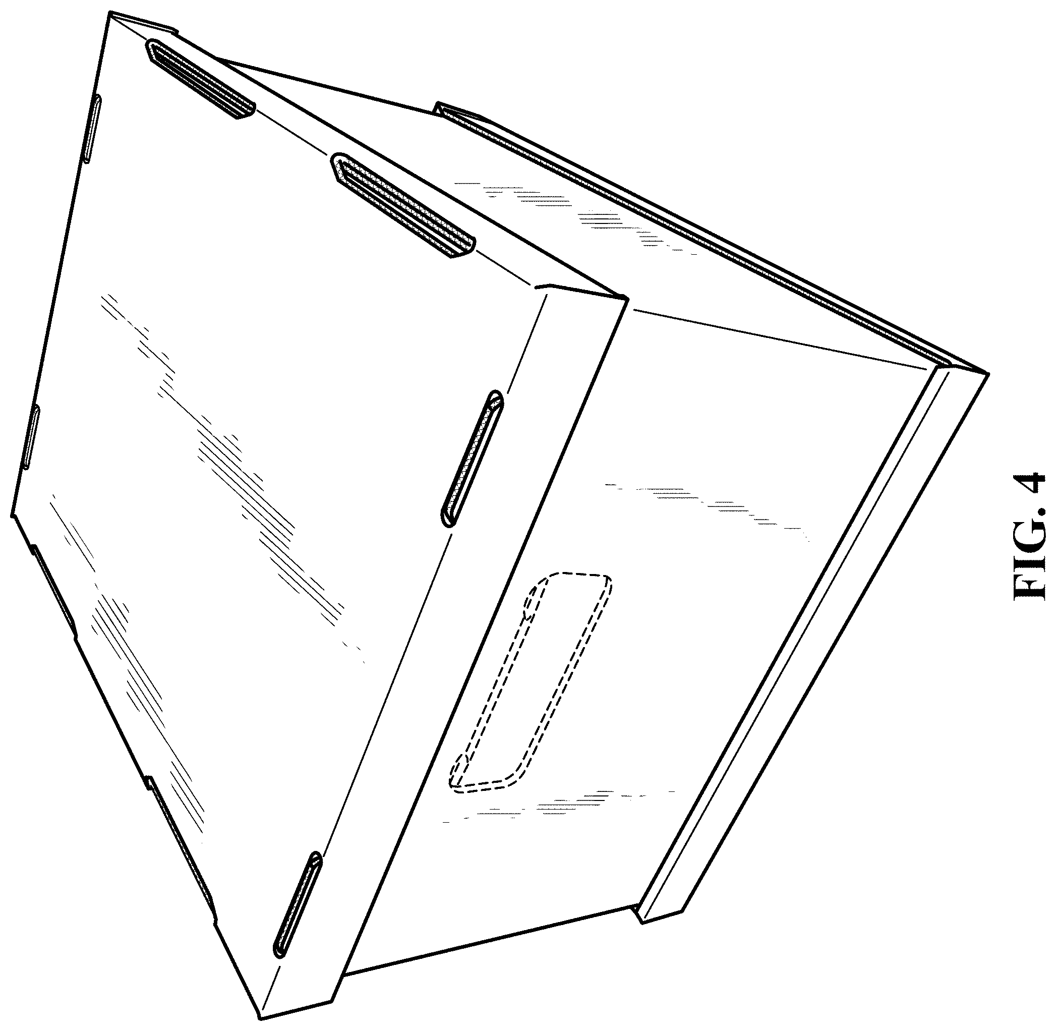
FIG. 4 is a top perspective view of the claimed design fully assembled.
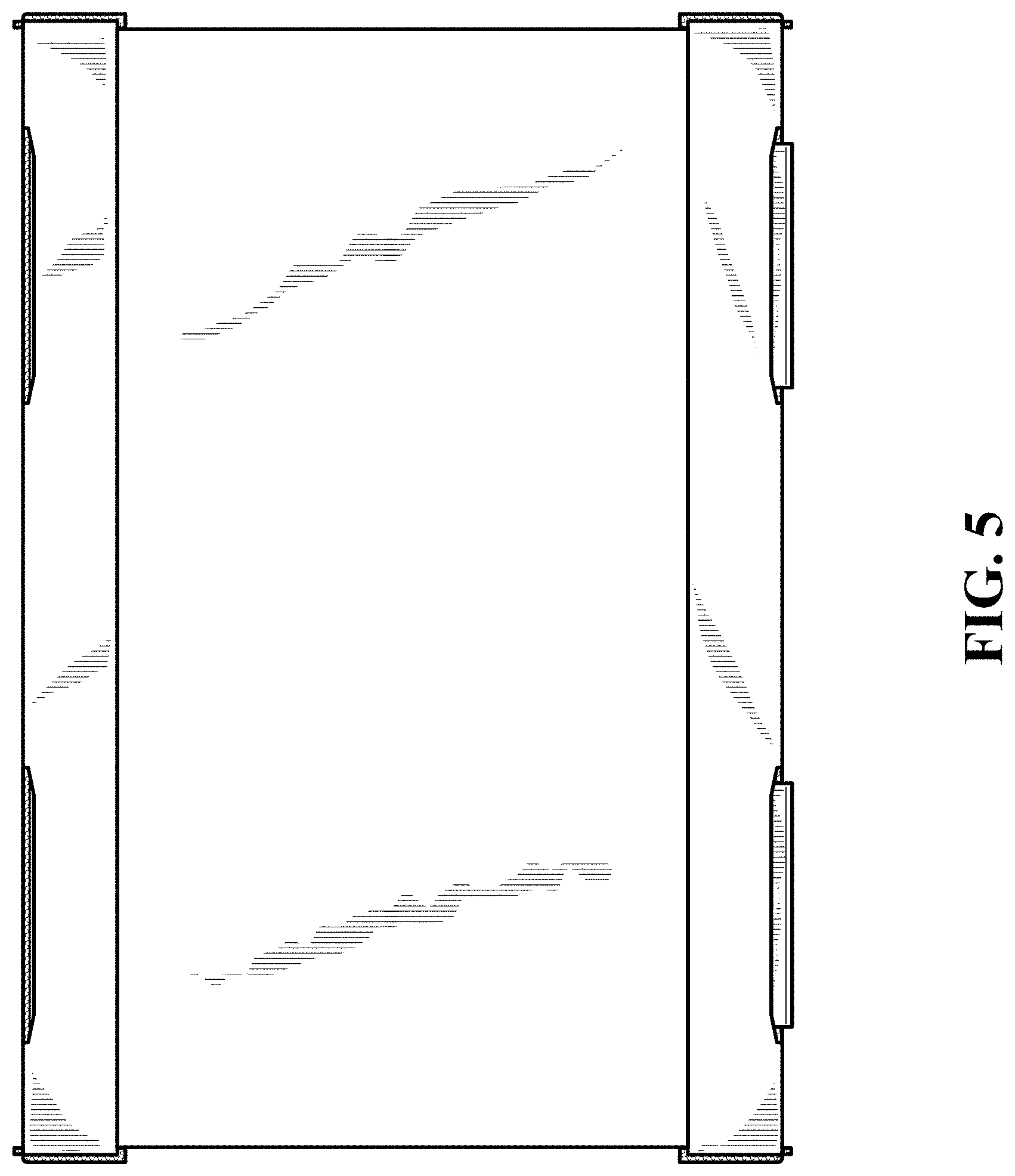
FIG. 5 is a right-side elevation view thereof.
FIG. 6 is a left-side elevation view thereof.
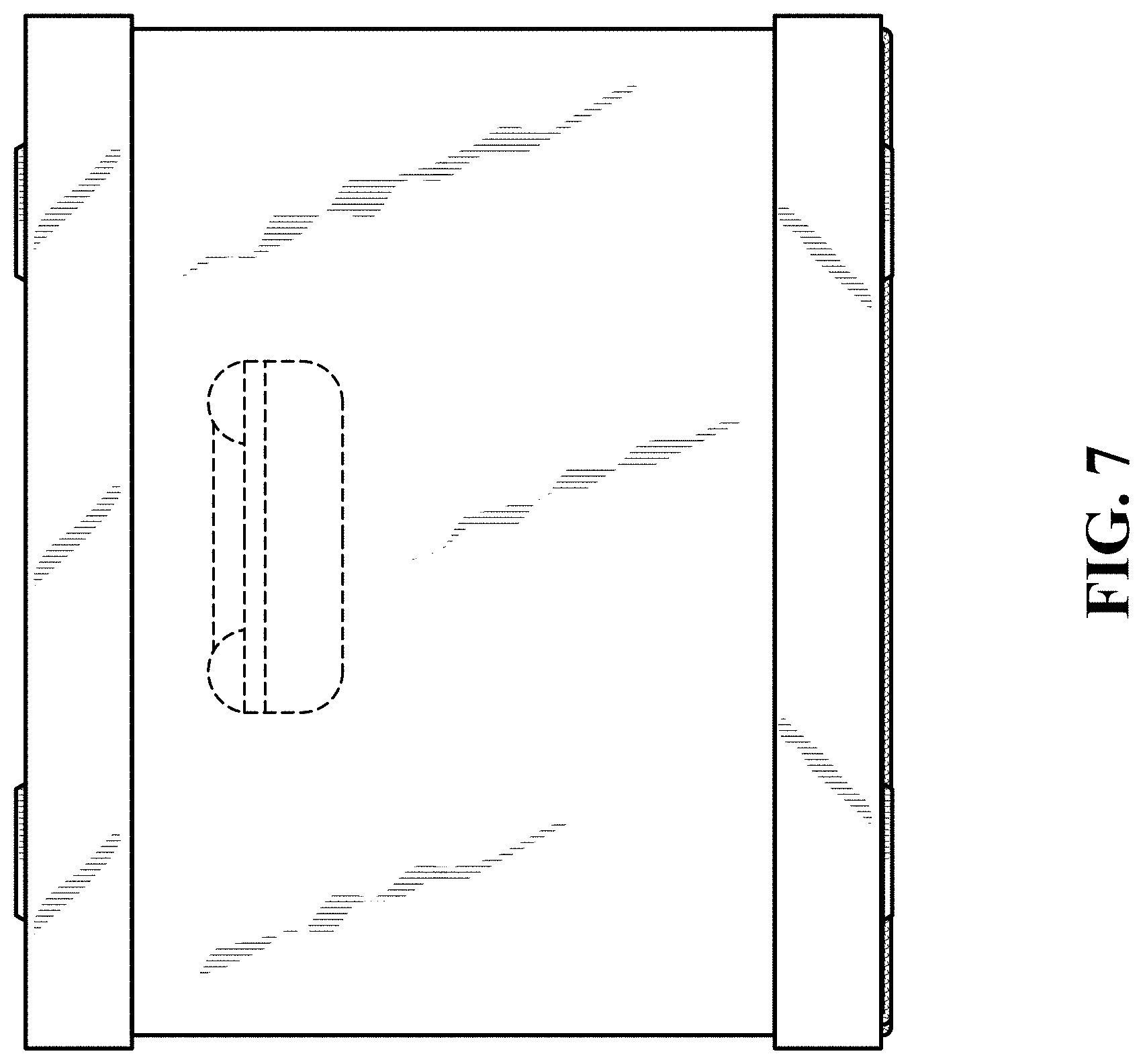
FIG. 7 is a front elevation view thereof.
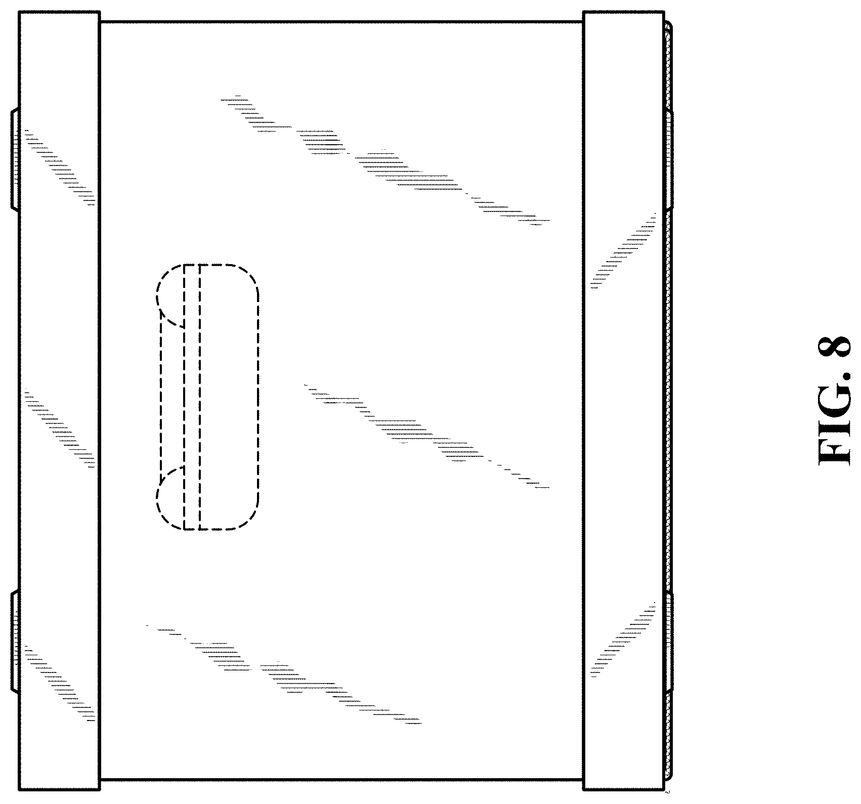
FIG. 8 is a rear elevation view thereof.
FIG. 9 is a top plan view thereof; and,
FIG. 10 is a bottom plan view thereof.
The solid lines in the drawings represent the bounds of the claimed design, whereas those features shown in broken lines, including a pair of handle cutouts shown in FIGS. 1-2, 4, and 7-8 and bend lines shown in FIGS. 1-3, form no part of the claimed design.
* * * * *
References
-
target.com/p/bankers-box-174-smoothmove-moving-storage-box-extra-strength-large-18w-x-18d-x-24h-kraft/-/A-16942594
-
officesupplyhut.com/Products/Bankers-Box-Recycled-StorFileandtrade----LetterLegal_FEL12770.aspx
-
rajapack.co.uk/cardboard-boxes/export-boxes/cardboard-cap-sleeve-loading-cases-without-pallets_PDT04683.html
-
thecustomboxes.com/cardboard-boxes
D00000
D00001
D00002
D00003
D00004
D00005
D00006
D00007
D00008
D00009
XML
uspto.report is an independent third-party trademark research tool that is not affiliated, endorsed, or sponsored by the United States Patent and Trademark Office (USPTO) or any other governmental organization. The information provided by uspto.report is based on publicly available data at the time of writing and is intended for informational purposes only.
While we strive to provide accurate and up-to-date information, we do not guarantee the accuracy, completeness, reliability, or suitability of the information displayed on this site. The use of this site is at your own risk. Any reliance you place on such information is therefore strictly at your own risk.
All official trademark data, including owner information, should be verified by visiting the official USPTO website at www.uspto.gov. This site is not intended to replace professional legal advice and should not be used as a substitute for consulting with a legal professional who is knowledgeable about trademark law.