Track rail for motion guide device
Mochizuki , et al. Feb
U.S. patent number D876,209 [Application Number D/603,367] was granted by the patent office on 2020-02-25 for track rail for motion guide device. This patent grant is currently assigned to THK CO., LTD.. The grantee listed for this patent is THK CO., LTD.. Invention is credited to Akito Kaneko, Hiroomi Kuribayashi, Hiroaki Mochizuki.


| United States Patent | D876,209 |
| Mochizuki , et al. | February 25, 2020 |
Track rail for motion guide device
Claims
CLAIM The ornamental design for a track rail for motion guide device, as shown and described.
| Inventors: | Mochizuki; Hiroaki (Tokyo, JP), Kuribayashi; Hiroomi (Tokyo, JP), Kaneko; Akito (Tokyo, JP) | ||||||||||
|---|---|---|---|---|---|---|---|---|---|---|---|
| Applicant: |
|
||||||||||
| Assignee: | THK CO., LTD. (Tokyo,
JP) |
||||||||||
| Appl. No.: | D/603,367 | ||||||||||
| Filed: | May 9, 2017 |
Foreign Application Priority Data
| Nov 16, 2016 [JP] | 2016-024900 | |||
| Current U.S. Class: | D8/377 |
| Current International Class: | 0805 |
| Field of Search: | ;D8/354,376,16,17,19,37,47,71,89,101,363,373,377,390,391,404 ;D6/512,524,528,534,672,680.1,680.2,705.7,708.25 ;D25/38.1,119,122,123 |
References Cited [Referenced By]
U.S. Patent Documents
| D31509 | September 1899 | Heib |
| 1933050 | October 1933 | Darrach, Jr. |
| D294209 | February 1988 | Havelka |
| D372662 | August 1996 | Atkinson |
| 6132093 | October 2000 | Michioka |
| 6262528 | July 2001 | Kim |
| D454960 | March 2002 | Michael |
| 6592261 | July 2003 | Mochizuki |
| D477986 | August 2003 | Barr |
| 6729760 | May 2004 | Mochizuki |
| D495850 | September 2004 | Washington |
| D521159 | May 2006 | Hansort |
| D530187 | October 2006 | Esbaugh |
| D542628 | May 2007 | Brassard |
| D545304 | June 2007 | Sergi |
| D551058 | September 2007 | Carnevali |
| D563768 | March 2008 | Marino |
| D596758 | July 2009 | Constable |
| D653206 | January 2012 | Heine |
| D666133 | August 2012 | In |
| 8251587 | August 2012 | Michioka |
| 8272783 | September 2012 | Mochizuki |
| D672287 | December 2012 | Noble |
| 8720937 | May 2014 | Noble |
| 9249828 | February 2016 | Horie |
| D757141 | May 2016 | Rechberg |
| 9458883 | October 2016 | Kadono |
| 9581204 | February 2017 | Yoshida |
| 9593715 | March 2017 | Mochizuki |
| 9863470 | January 2018 | Tomita |
| 2005/0173195 | August 2005 | Anita |
Other References
|
Hole Wizard Solidworks, posted Mar. 4, 2017, [retrieved Mar. 12, 2018]. Retrieved from Internet, <URL: https://www.youtube.com/watch?v=p1iMcDFu-jc >. cited by examiner . Mech Linear Systems, posted unknown, [retrieved Mar. 12, 2018]. Retrieved from Internet, <URL: https://mechlinearsystems.weebly.com/ >. cited by examiner . Home / Brand / PMI / Ball Recirculating Series / MSC--Miniature Type / PMI MSC Series, posted Apr. 2016, [retrieved Mar. 12, 2018]. Retrieved from Internet, <URL: http://accu-techusa.com/site/wp-content/uploads/2016/04/General-Catalog_E- _GW-MSC_MSD.pdf >. cited by examiner . Mini MGN9 9mm miniature linear guide MGN9 400mm linear rail way + MGN9C or MGN9H, posted unknown, [retrieved Mar. 12, 2018]. Retrieved from Internet, <URL: https://www.aliexpress.com/item/Miniature-Linear-Guide-Rail-2pcs-MGN9-400- mm-4pcs-MGN9C-slider-MGN-CNC-parts/32802131999.html >. cited by examiner. |
Primary Examiner: Kearney; Karen E
Assistant Examiner: Reed; Kristin E
Attorney, Agent or Firm: Westerman, Hattori, Daniels & Adrian, LLP Parker; Stephen B.
Description
FIG. 1 is a front elevational view of a track rail for motion guide device, showing our new design.
FIG. 2 is a rear elevational view thereof.
FIG. 3 is a right side elevational view thereof.
FIG. 4 is a left side elevational view thereof.
FIG. 5 is a top plan view thereof.
FIG. 6 is a bottom plan view thereof.
FIG. 7 is a cross-sectional view thereof, taken along line 7-7 of FIG. 5.
FIG. 8 is an enlarged view thereof, showing the section marked 8-8 of FIG. 7.
FIG. 9 is a cross-sectional view thereof, taken along line 9-9 of FIG. 5.
FIG. 10 is an enlarged cross-sectional view thereof, taken along line 9-9 of FIG. 5.
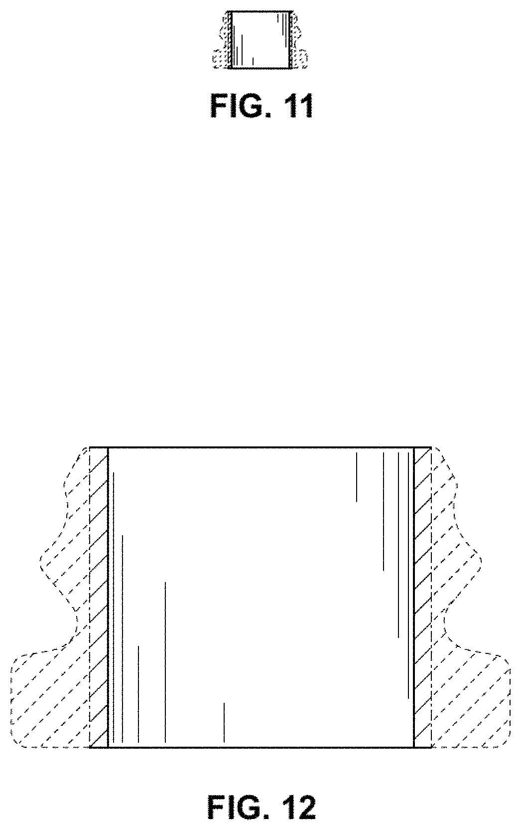
FIG. 11 is a cross-sectional view thereof, taken along line 11-11 of FIG. 5; and,
FIG. 12 is an enlarged cross-sectional view thereof, taken along 11-11 of FIG. 5.
The broken lines illustrate environmental structure and form no part of the claimed design. The dot-dash lines form boundaries of the claimed design and form no part thereof.
* * * * *
References
D00000
D00001
D00002
D00003
D00004
D00005
D00006
XML
uspto.report is an independent third-party trademark research tool that is not affiliated, endorsed, or sponsored by the United States Patent and Trademark Office (USPTO) or any other governmental organization. The information provided by uspto.report is based on publicly available data at the time of writing and is intended for informational purposes only.
While we strive to provide accurate and up-to-date information, we do not guarantee the accuracy, completeness, reliability, or suitability of the information displayed on this site. The use of this site is at your own risk. Any reliance you place on such information is therefore strictly at your own risk.
All official trademark data, including owner information, should be verified by visiting the official USPTO website at www.uspto.gov. This site is not intended to replace professional legal advice and should not be used as a substitute for consulting with a legal professional who is knowledgeable about trademark law.