Printer
Zanzotti Feb
U.S. patent number D875,826 [Application Number D/656,967] was granted by the patent office on 2020-02-18 for printer. This patent grant is currently assigned to Durst Phototechnik Digital Technology GmbH. The grantee listed for this patent is Durst Phototechnik Digital Technology GmbH. Invention is credited to Christian Zanzotti.


| United States Patent | D875,826 |
| Zanzotti | February 18, 2020 |
Printer
Claims
CLAIM The ornamental design for a printer, as shown and described.
| Inventors: | Zanzotti; Christian (Munchen, DE) | ||||||||||
|---|---|---|---|---|---|---|---|---|---|---|---|
| Applicant: |
|
||||||||||
| Assignee: | Durst Phototechnik Digital
Technology GmbH (Lienz, AT) |
||||||||||
| Appl. No.: | D/656,967 | ||||||||||
| Filed: | July 18, 2018 |
Foreign Application Priority Data
| Jan 24, 2018 [EP] | 004678530 | |||
| Jun 26, 2018 [EP] | 005325230 | |||
| Current U.S. Class: | D18/53 |
| Current International Class: | 1802 |
| Field of Search: | ;D18/50,53,54,55,56,59,36,37,38,39,40,41,45 ;D14/301,307,121 |
References Cited [Referenced By]
U.S. Patent Documents
| D352732 | November 1994 | Dubson |
| D356596 | March 1995 | Dubson |
| D368435 | April 1996 | Caamano |
| D381682 | July 1997 | Bornhorst, Jr. |
| D455456 | April 2002 | Angelbeck |
| D544534 | June 2007 | Reece |
| D614233 | April 2010 | Kemmochi |
| D640737 | June 2011 | Tsuruta |
| D648783 | November 2011 | Mathea |
| D650417 | December 2011 | Brown |
| D666666 | September 2012 | Brown |
| D837290 | January 2019 | Umezawa |
| 2010/0059920 | March 2010 | Kern |
| 301263937 | Jun 2010 | CN | |||
| 303266842 | Jul 2015 | CN | |||
| 303409482 | Oct 2015 | CN | |||
Other References
|
YouTube. Link: https://www.youtube.com/watch?v=Y1LIOrxlp54. Feb. 8, 2018. Durst P5--The Master Class. (Year: 2018). cited by examiner. |
Primary Examiner: Hattan; Susan Bennett
Assistant Examiner: McVey; Lauren D
Attorney, Agent or Firm: Brinks Gilson & Lione
Description
FIG. 1 is a rear side elevation view of a first embodiment of a printer, showing my new design;
FIG. 2 is a bottom plan view of the printer of FIG. 1;
FIG. 3 is a front side elevation view of the printer of FIG. 1;
FIG. 4 is a left-side elevation view of the printer of FIG. 1;
FIG. 5 is a front perspective view of the printer of FIG. 1;
FIG. 6 is a right-side elevation view of the printer of FIG. 1;
FIG. 7 is a top plan view of the printer design of FIG. 1;
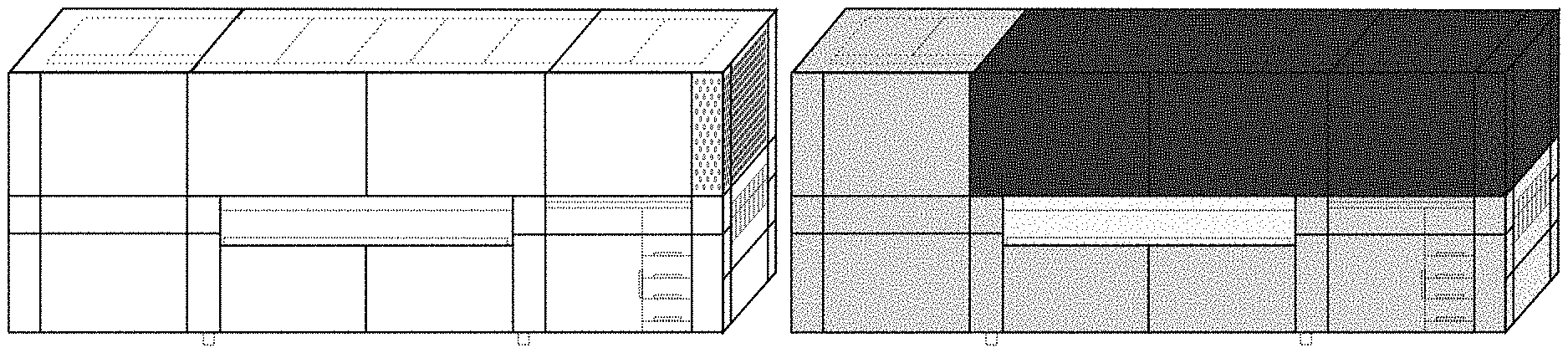
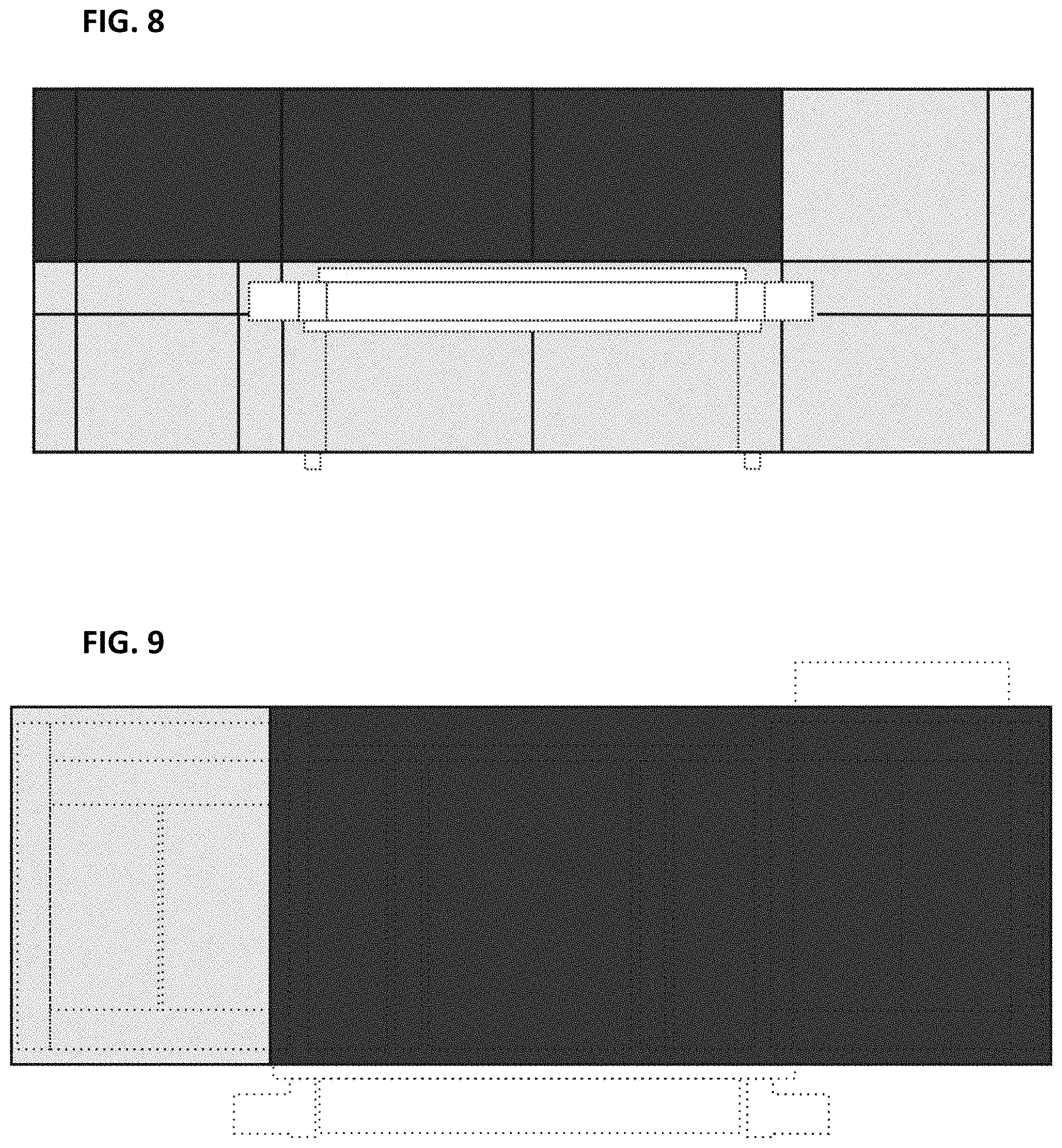
FIG. 8 is a rear side elevation view of a second embodiment of the printer;
FIG. 9 is a bottom plan view of the printer of FIG. 8;
FIG. 10 is a side elevation view of the printer of FIG. 8;
FIG. 11 is a left-side elevation view of the printer of FIG. 8;
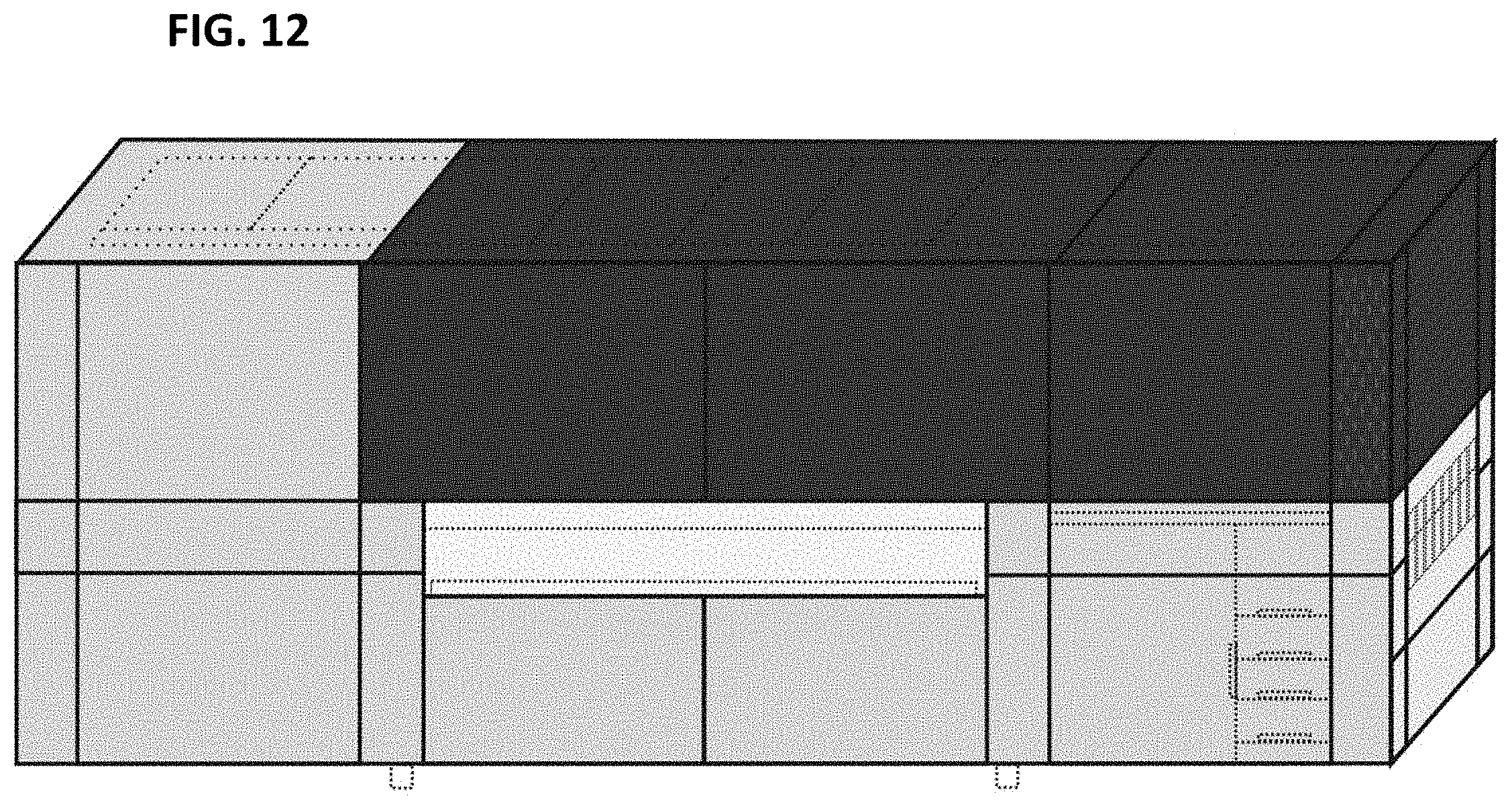
FIG. 12 is a front perspective view of the printer of FIG. 8;
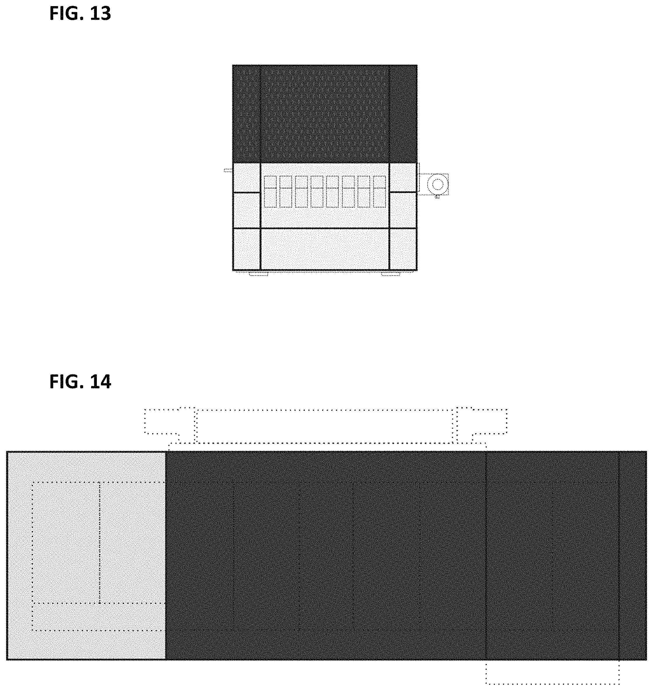
FIG. 13 is a right-side elevation view of the printer of FIG. 8; and,
FIG. 14 is a top plan view of the printer of FIG. 8.
The broken lines are included for the purpose of illustrating environmental structure and form no part of the claimed design.
The structures are identical in both embodiments.
* * * * *
References
D00000
D00001
D00002
D00003
D00004
D00005
D00006
D00007
D00008
XML
uspto.report is an independent third-party trademark research tool that is not affiliated, endorsed, or sponsored by the United States Patent and Trademark Office (USPTO) or any other governmental organization. The information provided by uspto.report is based on publicly available data at the time of writing and is intended for informational purposes only.
While we strive to provide accurate and up-to-date information, we do not guarantee the accuracy, completeness, reliability, or suitability of the information displayed on this site. The use of this site is at your own risk. Any reliance you place on such information is therefore strictly at your own risk.
All official trademark data, including owner information, should be verified by visiting the official USPTO website at www.uspto.gov. This site is not intended to replace professional legal advice and should not be used as a substitute for consulting with a legal professional who is knowledgeable about trademark law.