Electronics device mount
Ramones , et al. Feb
U.S. patent number D875,736 [Application Number D/673,611] was granted by the patent office on 2020-02-18 for electronics device mount. This patent grant is currently assigned to Arlo Technologies, Inc.. The grantee listed for this patent is Arlo Technologies, Inc.. Invention is credited to Christopher Vincent Fonzo, Beau Oyler, John Kui Yin Ramones, Dayne Nathaniel Tanner.


| United States Patent | D875,736 |
| Ramones , et al. | February 18, 2020 |
Electronics device mount
Claims
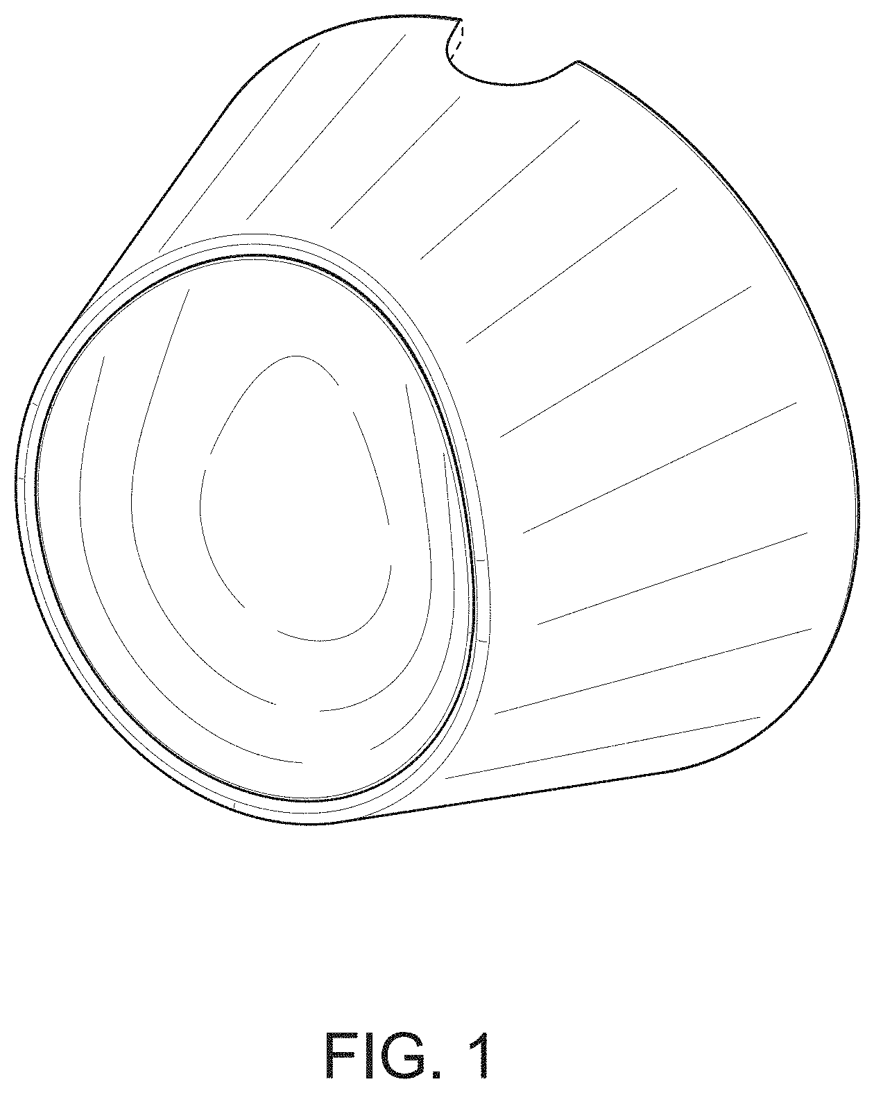
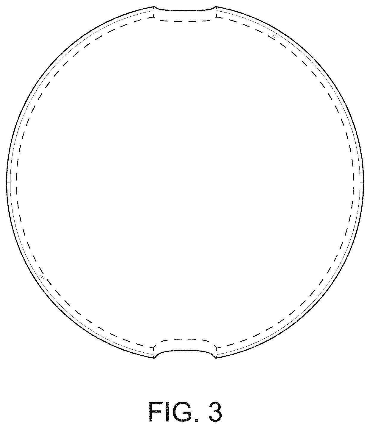
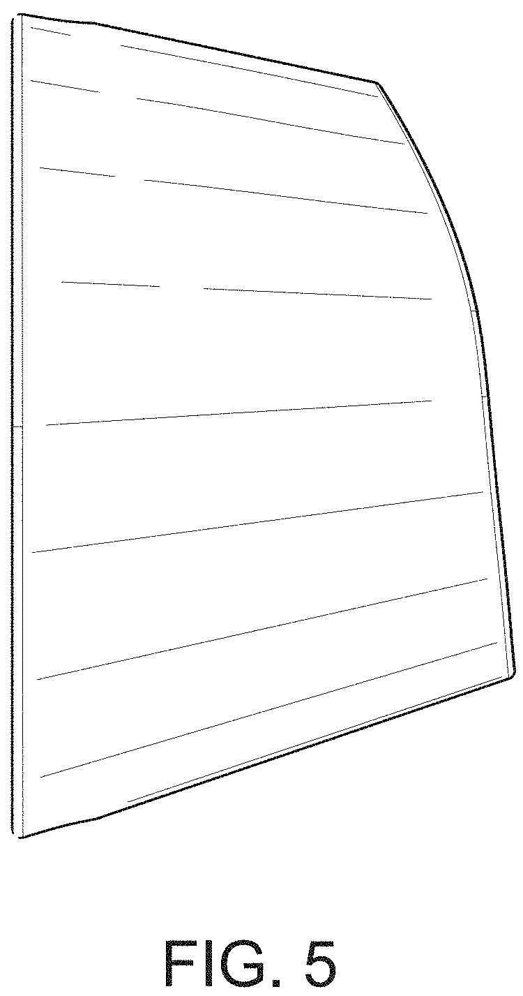
CLAIM The ornamental design for an electronics device mount, as shown and described.
| Inventors: | Ramones; John Kui Yin (San Ramon, CA), Fonzo; Christopher Vincent (Carlsbad, CA), Oyler; Beau (Walnut Creek, CA), Tanner; Dayne Nathaniel (Concord, CA) | ||||||||||
|---|---|---|---|---|---|---|---|---|---|---|---|
| Applicant: |
|
||||||||||
| Assignee: | Arlo Technologies, Inc.
(Carlsbad, CA) |
||||||||||
| Appl. No.: | D/673,611 | ||||||||||
| Filed: | December 17, 2018 |
| Current U.S. Class: | D14/447 |
| Current International Class: | 0807 |
| Field of Search: | ;D14/447,432,434,439,440,451,452,457,239,253 ;D8/363,373,380 ;D6/406.3,406.4,406.5,406.6 ;D12/415 ;D13/108 |
References Cited [Referenced By]
U.S. Patent Documents
| 1800797 | April 1931 | Hoople |
| 2752116 | June 1956 | Minnis |
| 4214724 | July 1980 | Geiger |
| 4974802 | December 1990 | Hendren |
| 6379073 | April 2002 | Yoo et al. |
| D460971 | July 2002 | Sica |
| D654866 | February 2012 | Rautiainen |
| D673528 | January 2013 | Trotsky |
| D686213 | July 2013 | Haymond |
| D692898 | November 2013 | Luijben |
| D693814 | November 2013 | Park |
| D706784 | June 2014 | Mills |
| D719959 | December 2014 | Vogel |
| D719961 | December 2014 | Xiang |
| D725660 | March 2015 | Trotsky |
| D789373 | June 2017 | King |
| 10038829 | July 2018 | Gilbert |
| D832859 | November 2018 | Charlesworth |
| D853323 | July 2019 | Minarsch |
| 2013/0163978 | June 2013 | Carlesso |
| 2018/0367713 | December 2018 | Gilbert |
Attorney, Agent or Firm: Boyle Fredrickson S.C.
Description
FIG. 1 is a top, front, right side perspective view of an electronics device mount showing our new design;
FIG. 2 is a front elevation view thereof;
FIG. 3 is a rear elevation view thereof;
FIG. 4 is a right-side elevation view thereof;
FIG. 5 is a left-side elevation view thereof;
FIG. 6 is a top plan view thereof; and,
FIG. 7 is a bottom plan view thereof.
The broken lines in FIGS. 1-7 represent the boundaries of the claimed design. All of the broken lines form no part of the claimed design.
* * * * *
D00000
D00001
D00002
D00003
D00004
D00005
D00006
D00007
XML
uspto.report is an independent third-party trademark research tool that is not affiliated, endorsed, or sponsored by the United States Patent and Trademark Office (USPTO) or any other governmental organization. The information provided by uspto.report is based on publicly available data at the time of writing and is intended for informational purposes only.
While we strive to provide accurate and up-to-date information, we do not guarantee the accuracy, completeness, reliability, or suitability of the information displayed on this site. The use of this site is at your own risk. Any reliance you place on such information is therefore strictly at your own risk.
All official trademark data, including owner information, should be verified by visiting the official USPTO website at www.uspto.gov. This site is not intended to replace professional legal advice and should not be used as a substitute for consulting with a legal professional who is knowledgeable about trademark law.