Location sensor and flow rate meter
Krywyj , et al. Feb
U.S. patent number D874,954 [Application Number D/643,348] was granted by the patent office on 2020-02-11 for location sensor and flow rate meter. This patent grant is currently assigned to Orbis Intelligent Systems, Inc.. The grantee listed for this patent is Orbis Intelligent Systems, Inc.. Invention is credited to Daniel Milne Krywyj, Jeffrey A. Prsha.


| United States Patent | D874,954 |
| Krywyj , et al. | February 11, 2020 |
Location sensor and flow rate meter
Claims
CLAIM We claim the ornamental design for a location sensor and flow rate meter, as shown and described.
| Inventors: | Krywyj; Daniel Milne (La Jolla, CA), Prsha; Jeffrey A. (San Diego, CA) | ||||||||||
|---|---|---|---|---|---|---|---|---|---|---|---|
| Applicant: |
|
||||||||||
| Assignee: | Orbis Intelligent Systems, Inc.
(San Diego, CA) |
||||||||||
| Appl. No.: | D/643,348 | ||||||||||
| Filed: | April 6, 2018 |
| Current U.S. Class: | D10/70; D10/46 |
| Current International Class: | 1004 |
| Field of Search: | ;D10/46,70 |
References Cited [Referenced By]
U.S. Patent Documents
| D699604 | February 2014 | Dunkin |
Other References
|
US. Appl. No. 29/650,752, filed Jun. 8, 2018, Krywyj, et al. cited by applicant . Australian Office Action dated Nov. 7, 2018, issued in Australian Patent Application No. 201815982. cited by applicant . New Zealand Office Action dated Oct. 24, 2018, issued in New Zealand Patent Application No. 425060. cited by applicant . Australian Office Action dated Jan. 14, 2019, issued in Australian Patent Application No. 201817338. cited by applicant . New Zealand Office Action dated Dec. 21, 2018, issued in New Zealand Patent Application No. 425481. cited by applicant . U.S. Appl. No. 29/674,638, filed Dec. 21, 2018, Krywyj et al. cited by applicant . Ex Parte Quayle Office Action dated Jun. 28, 2019 in U.S. Appl. No. 29/650,752. cited by applicant . US Notice of Allowance dated Oct. 31, 2019 in U.S. Design Appl. No. 29/650,752. cited by applicant . Canadian Examination Report dated Dec. 3, 2019 in CA Design Application No. 185082. cited by applicant . New Zealand Examination Report dated Oct. 18, 2019 in NZ Design Application No. 425481. cited by applicant. |
Primary Examiner: Davis; Antoine Duval
Attorney, Agent or Firm: Weaver Austin Villeneuve & Sampson LLP
Description
FIG. 1 depicts an isometric view of an example location sensor and flow rate meter.
FIG. 2 depicts a front view of the location sensor and flow rate meter of FIG. 1.
FIG. 3 depicts a back view of the location sensor and flow rate meter of FIG. 1.
FIG. 4 depicts a side view of the location sensor and flow rate meter of FIG. 1.
FIG. 5 depicts an opposite side view of the location sensor and flow rate meter of FIG. 1.
FIG. 6 depicts an off-angle view of the location sensor and flow rate meter of FIG. 1.
FIG. 7 depicts another off-angle view of the location sensor and flow rate meter of FIG. 1.
FIG. 8 depicts a top view of the location sensor and flow rate meter of FIG. 1.
FIG. 9 depicts a bottom view of the location sensor and flow rate meter of FIG. 1.
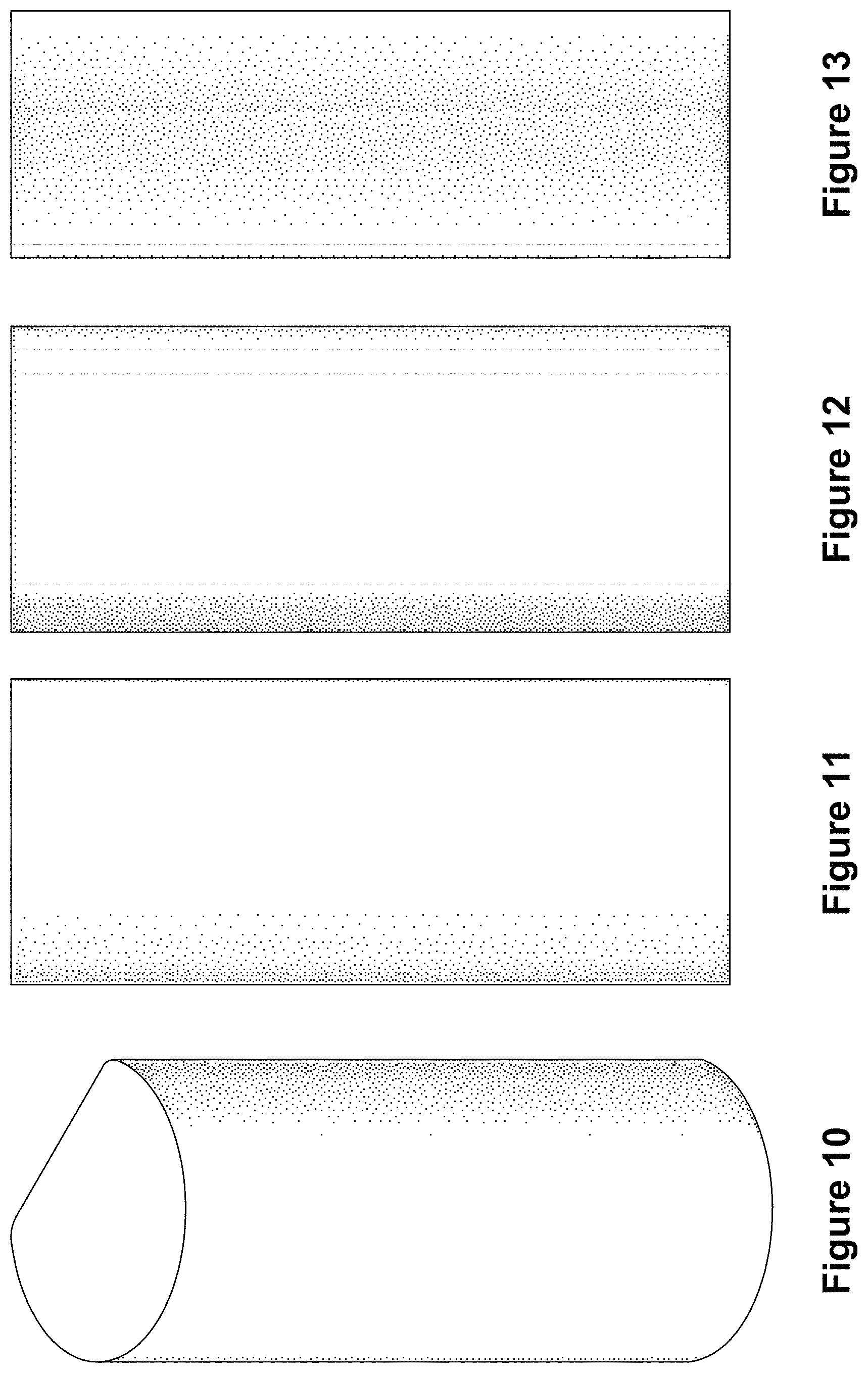
FIG. 10 depicts an isometric view of another example location sensor and flow rate meter.
FIG. 11 depicts a front view of the location sensor and flow rate meter of FIG. 10.
FIG. 12 depicts a back view of the location sensor and flow rate meter of FIG. 10.
FIG. 13 depicts a side view of the location sensor and flow rate meter of FIG. 10.
FIG. 14 depicts an opposite side view of the location sensor and flow rate meter of FIG. 10.
FIG. 15 depicts an off-angle view of the location sensor and flow rate meter of FIG. 10.
FIG. 16 depicts another off-angle view of the location sensor and flow rate meter of FIG. 10.
FIG. 17 depicts a top view of the location sensor and flow rate meter of FIG. 10; and,
FIG. 18 depicts a bottom view of the location sensor and flow rate meter of FIG. 10.
The location sensor and flow rate meter in the accompanying figures may be positioned on or near a fluid conduit, such as a pipe or a standpipe.
Stipple shading is used in all of the accompanying Figures to convey surface contouring and not texture.
The tangent edges, for the sake of clarity, represent transitions between a surface and a rounded surface, i.e., where these two surfaces are tangent to one another.
* * * * *
D00000
D00001
D00002
D00003
D00004
XML
uspto.report is an independent third-party trademark research tool that is not affiliated, endorsed, or sponsored by the United States Patent and Trademark Office (USPTO) or any other governmental organization. The information provided by uspto.report is based on publicly available data at the time of writing and is intended for informational purposes only.
While we strive to provide accurate and up-to-date information, we do not guarantee the accuracy, completeness, reliability, or suitability of the information displayed on this site. The use of this site is at your own risk. Any reliance you place on such information is therefore strictly at your own risk.
All official trademark data, including owner information, should be verified by visiting the official USPTO website at www.uspto.gov. This site is not intended to replace professional legal advice and should not be used as a substitute for consulting with a legal professional who is knowledgeable about trademark law.