Robotic arm
Vazquez Ja
U.S. patent number D873,878 [Application Number D/634,027] was granted by the patent office on 2020-01-28 for robotic arm. This patent grant is currently assigned to AURIS HEALTH, INC.. The grantee listed for this patent is Auris Health, Inc.. Invention is credited to Frankie Vazquez.


| United States Patent | D873,878 |
| Vazquez | January 28, 2020 |
Robotic arm
Claims
CLAIM The ornamental design for a robotic arm, as shown and described.
| Inventors: | Vazquez; Frankie (San Francisco, CA) | ||||||||||
|---|---|---|---|---|---|---|---|---|---|---|---|
| Applicant: |
|
||||||||||
| Assignee: | AURIS HEALTH, INC. (Redwood
City, CA) |
||||||||||
| Appl. No.: | D/634,027 | ||||||||||
| Filed: | January 17, 2018 |
| Current U.S. Class: | D15/199 |
| Current International Class: | 1599 |
| Field of Search: | ;D12/177 ;D15/122,199 ;D21/578-583,621,622 |
References Cited [Referenced By]
U.S. Patent Documents
| D650820 | December 2011 | Long |
| D766348 | September 2016 | Long |
| D769343 | October 2016 | Bordegnoni |
| 9561083 | February 2017 | Yu et al. |
| 9622827 | April 2017 | Yu et al. |
| 9636184 | May 2017 | Lee et al. |
| 9713509 | July 2017 | Schuh et al. |
| 9727963 | August 2017 | Mintz et al. |
| 9737371 | August 2017 | Romo et al. |
| 9737373 | August 2017 | Schuh |
| 9744335 | August 2017 | Jiang |
| 9763741 | September 2017 | Alvarez et al. |
| 9788910 | October 2017 | Schuh |
| D802041 | November 2017 | He |
| 9818681 | November 2017 | Machida |
| 9844412 | December 2017 | Bogusky et al. |
| 9867635 | January 2018 | Alvarez et al. |
| 9931025 | April 2018 | Graetzel et al. |
| 9949749 | April 2018 | Noonan et al. |
| 9955986 | May 2018 | Shah |
| 9962228 | May 2018 | Schuh et al. |
| 9980785 | May 2018 | Schuh |
| 9993313 | June 2018 | Schuh et al. |
| 10016900 | July 2018 | Meyer et al. |
| 10022192 | July 2018 | Ummalaneni |
| D839941 | February 2019 | Gao |
| 2010/0145510 | June 2010 | Ihrke |
| 2014/0142591 | May 2014 | Alvarez et al. |
| 2014/0207279 | July 2014 | Miyauchi |
| 2014/0309649 | October 2014 | Alvarez et al. |
| 2014/0357984 | December 2014 | Wallace et al. |
| 2014/0364870 | December 2014 | Alvarez et al. |
| 2014/0379000 | December 2014 | Romo et al. |
| 2015/0051592 | February 2015 | Kintz |
| 2015/0101442 | April 2015 | Romo |
| 2015/0119638 | April 2015 | Yu et al. |
| 2015/0133960 | May 2015 | Lohmeier |
| 2015/0164594 | June 2015 | Romo et al. |
| 2015/0164596 | June 2015 | Romo |
| 2015/0335480 | November 2015 | Alvarez et al. |
| 2016/0001038 | January 2016 | Romo et al. |
| 2016/0270865 | September 2016 | Landey et al. |
| 2016/0287279 | October 2016 | Bovay et al. |
| 2016/0296294 | October 2016 | Moll et al. |
| 2016/0374541 | December 2016 | Agrawal et al. |
| 2017/0007337 | January 2017 | Dan |
| 2017/0100199 | April 2017 | Yu et al. |
| 2017/0119413 | May 2017 | Romo |
| 2017/0119481 | May 2017 | Romo et al. |
| 2017/0165011 | June 2017 | Bovay et al. |
| 2017/0172673 | June 2017 | Yu et al. |
| 2017/0202627 | July 2017 | Sramek et al. |
| 2017/0209073 | July 2017 | Sramek et al. |
| 2017/0290631 | October 2017 | Lee et al. |
| 2017/0333679 | November 2017 | Jiang |
| 2017/0340396 | November 2017 | Romo et al. |
| 2017/0365055 | December 2017 | Mintz et al. |
| 2017/0367782 | December 2017 | Schuh et al. |
| 2018/0025666 | January 2018 | Ho et al. |
| 2018/0177383 | June 2018 | Noonan et al. |
| 2018/0177556 | June 2018 | Noonan et al. |
| 2018/0177561 | June 2018 | Mintz et al. |
| 2018/0207795 | July 2018 | Haddadin |
| 2018/0214011 | August 2018 | Graetzei et al. |
| 2018/0221038 | August 2018 | Noonan et al. |
| 2018/0221039 | August 2018 | Shah |
| 2018/0235724 | August 2018 | Nowatschin |
| 2018/0370026 | December 2018 | Reese |
| 2019/0047160 | February 2019 | Weitschat |
| 2019/0099901 | April 2019 | Niu |
Attorney, Agent or Firm: Knobbe Martens Olson & Bear LLP
Description
FIG. 1 is a top, front, right perspective view of a robotic arm;
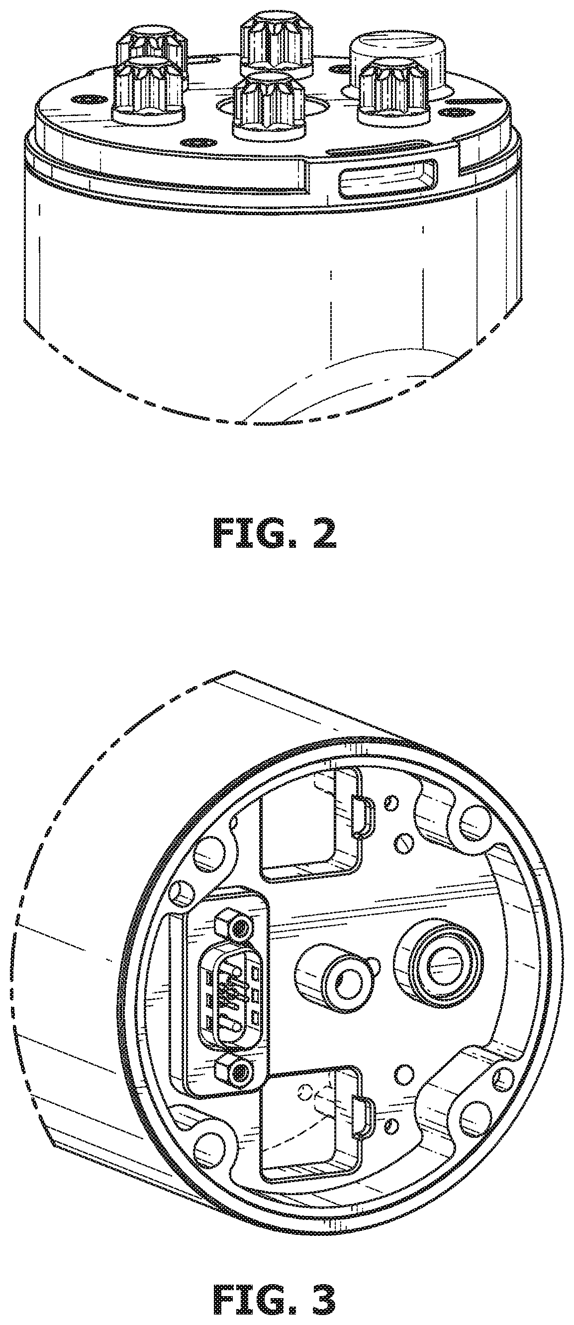
FIG. 2 is an enlarged view of portion 2 encircled in FIG. 1;
FIG. 3 is an enlarged view of portion 3 encircled in FIG. 1;
FIG. 4 is a right-side view of the robotic arm;
FIG. 5 is an enlarged view of portion 5 encircled in FIG. 4;
FIG. 6 is a left-side view of the robotic arm;
FIG. 7 is an enlarged view of portion 7 encircled in FIG. 6;
FIG. 8 is a rear view of the robotic arm;
FIG. 9 is an enlarged view of portion 9 encircled in FIG. 8;
FIG. 10 is a front view of the first embodiment;
FIG. 11 is an enlarged view of portion 11 encircled in FIG. 10;
FIG. 12 is an enlarged view of portion 12 encircled in FIG. 10;
FIG. 13 is a top plan view of the first embodiment;
FIG. 14 is an enlarged view of portion 14 encircled in FIG. 13; and,
FIG. 15 is a bottom plan view of the robotic arm.
The broken lines illustrate portions of the robotic arm and form no part of the claimed subject matter.
* * * * *
D00000
D00001
D00002
D00003
D00004
D00005
D00006
D00007
D00008
D00009
XML
uspto.report is an independent third-party trademark research tool that is not affiliated, endorsed, or sponsored by the United States Patent and Trademark Office (USPTO) or any other governmental organization. The information provided by uspto.report is based on publicly available data at the time of writing and is intended for informational purposes only.
While we strive to provide accurate and up-to-date information, we do not guarantee the accuracy, completeness, reliability, or suitability of the information displayed on this site. The use of this site is at your own risk. Any reliance you place on such information is therefore strictly at your own risk.
All official trademark data, including owner information, should be verified by visiting the official USPTO website at www.uspto.gov. This site is not intended to replace professional legal advice and should not be used as a substitute for consulting with a legal professional who is knowledgeable about trademark law.