Control device
Altonen , et al. Ja
U.S. patent number D873,222 [Application Number D/635,800] was granted by the patent office on 2020-01-21 for control device. This patent grant is currently assigned to Lutron Technology Company LLC. The grantee listed for this patent is Lutron Technology Company LLC. Invention is credited to Gregory S. Altonen, Nikhil V. Bhate, Jonathan Dersch, Jason C. Killo, Brad M. Kreschollek, Ritesh Maharjan, Matthew P. McDonald.


View All Diagrams
| United States Patent | D873,222 |
| Altonen , et al. | January 21, 2020 |
Control device
Claims
CLAIM The ornamental design for a control device, as shown and described.
| Inventors: | Altonen; Gregory S. (Easton, PA), Bhate; Nikhil V. (East Norriton, PA), Dersch; Jonathan (Fountain Hill, PA), Killo; Jason C. (Emmaus, PA), Kreschollek; Brad M. (Bethlehem, PA), Maharjan; Ritesh (Bethlehem, PA), McDonald; Matthew P. (Phoenixville, PA) | ||||||||||
|---|---|---|---|---|---|---|---|---|---|---|---|
| Applicant: |
|
||||||||||
| Assignee: | Lutron Technology Company LLC
(Coopersburg, PA) |
||||||||||
| Appl. No.: | D/635,800 | ||||||||||
| Filed: | February 2, 2018 |
| Current U.S. Class: | D13/168 |
| Current International Class: | 1403 |
| Field of Search: | ;D13/137.3,158,162,168,171 |
References Cited [Referenced By]
U.S. Patent Documents
| D307579 | May 1990 | Layne |
| 6005210 | December 1999 | Chien |
| 6255613 | July 2001 | Yang |
| D626921 | November 2010 | Pang |
| D630593 | January 2011 | Clymer |
| 8008628 | August 2011 | Boucly |
| D726130 | April 2015 | Burgett |
| 9332615 | May 2016 | Peng |
| 9666006 | May 2017 | Kramer |
| D818971 | May 2018 | Peng |
| D830979 | October 2018 | Hung |
| 2011/0050106 | March 2011 | Yang |
| 2012/0305375 | December 2012 | Kwok |
| 2016/0380424 | December 2016 | Aromin |
Other References
|
Inline Switches and Dimmers ; prior to Feb. 2, 2018; 1 pg. https://www.google.com/search?hl=en&biw=1536&bih=813&tbs=cdr%3A1%2Ccd_max- %3A2%2F2%2F2017&tbm =isch&sa=1&ei=a9Z3XdalM_GO5wL1kJ6IBQ&q=+in+line+lamp+dimmer+switch&oq=+in- +line+lamp+dimmer+switch&gs_i=img.3..0.226158.232292..232772...0.0..0.70.3- 32.6......0 . . . cited by examiner. |
Primary Examiner: Sikder; Selina
Attorney, Agent or Firm: Smith; Philip Farbanish; Glen Yanek; Amy
Description
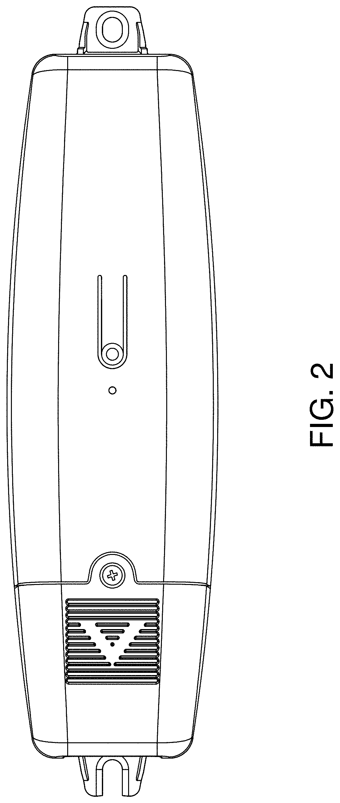
FIG. 1 is a front perspective view of a control device showing our new design.
FIG. 2 is a front view thereof.
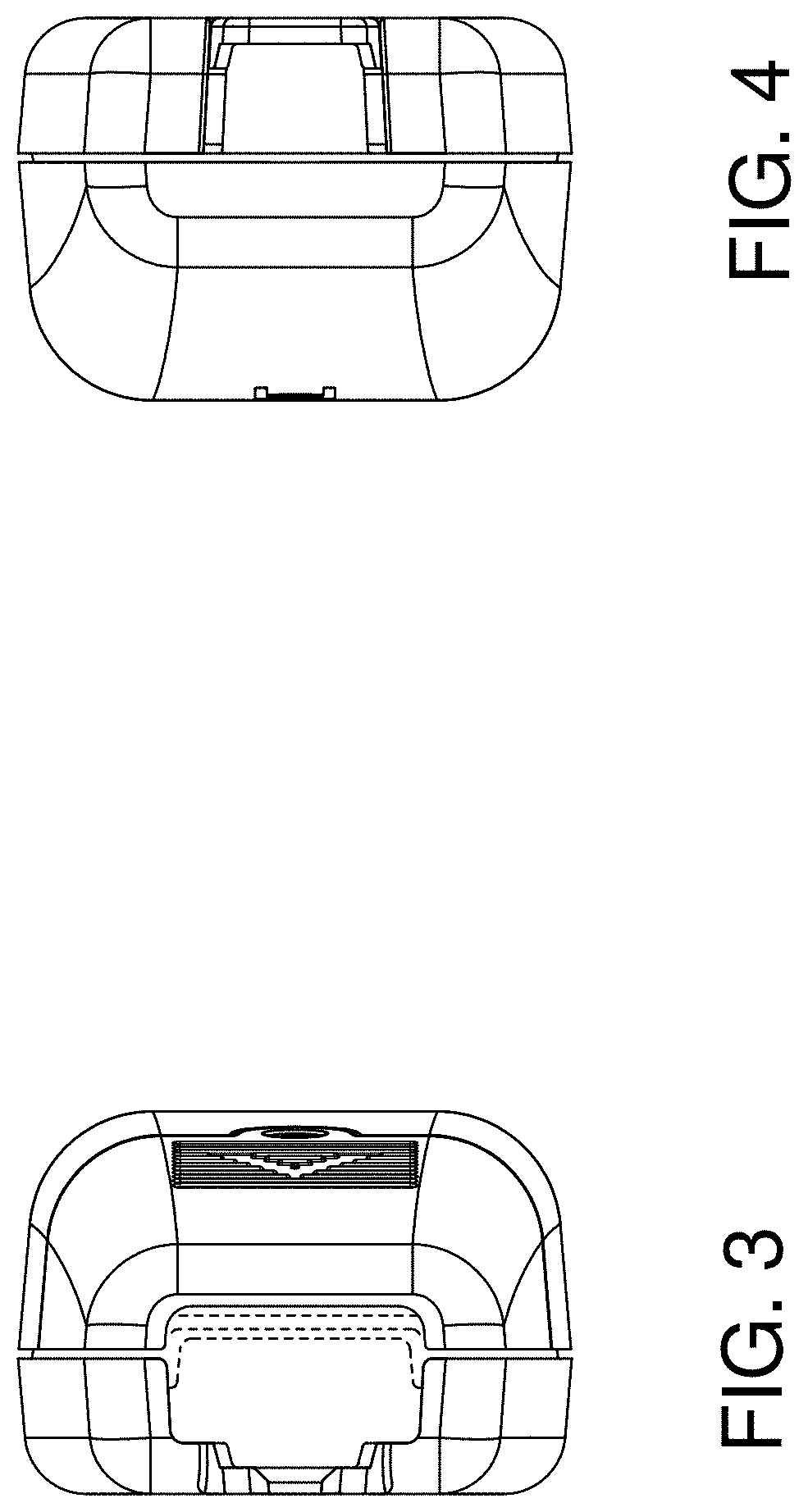
FIG. 3 is a left side view thereof.
FIG. 4 is a right side view thereof.
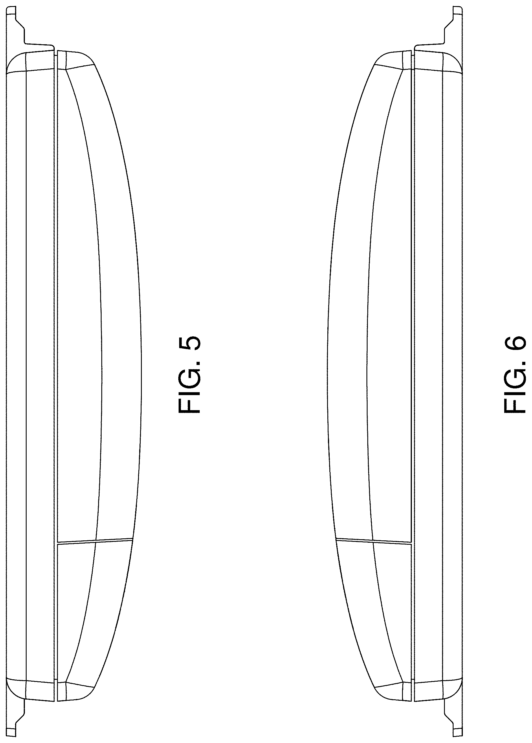
FIG. 5 is a top view thereof.
FIG. 6 is a bottom view thereof.
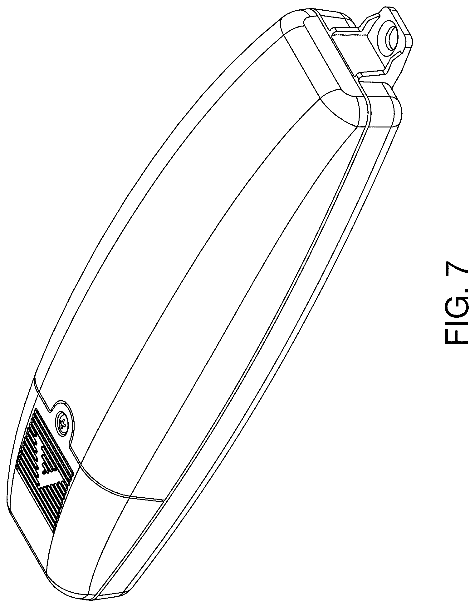
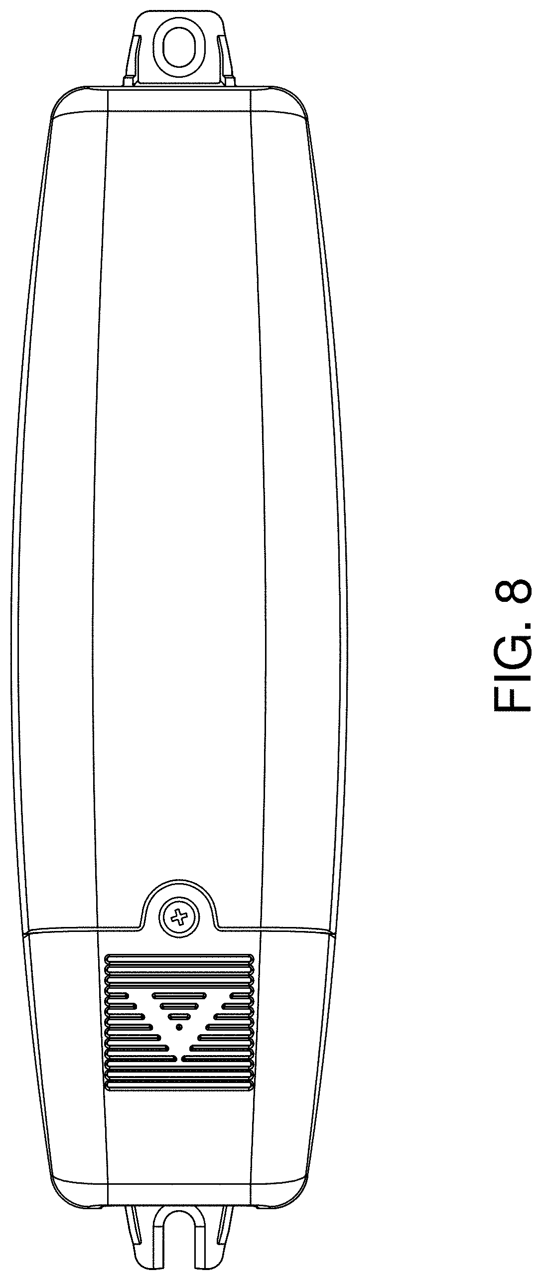
FIG. 7 is a front perspective view of a second embodiment thereof.
FIG. 8 is a front view thereof.
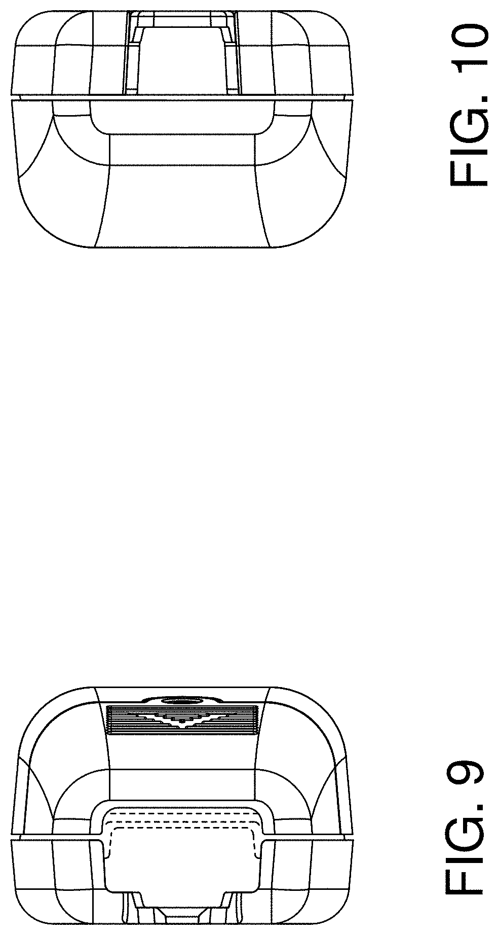
FIG. 9 is a left side view thereof.
FIG. 10 is a right side view thereof.
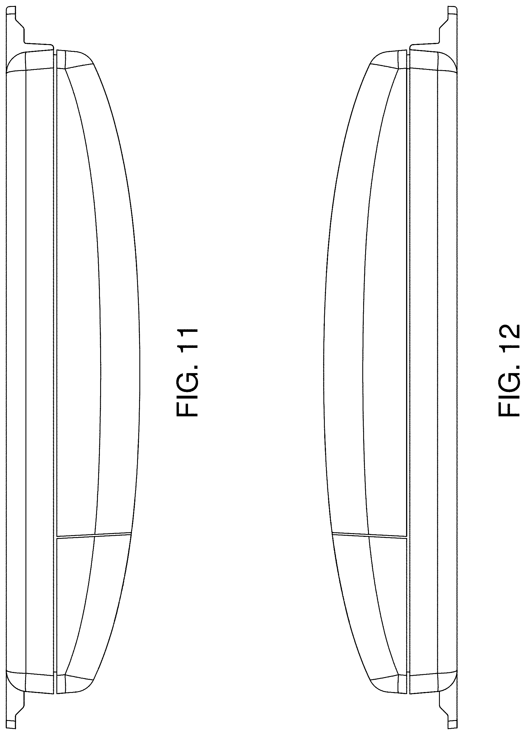
FIG. 11 is a top view thereof.
FIG. 12 is a bottom view thereof.
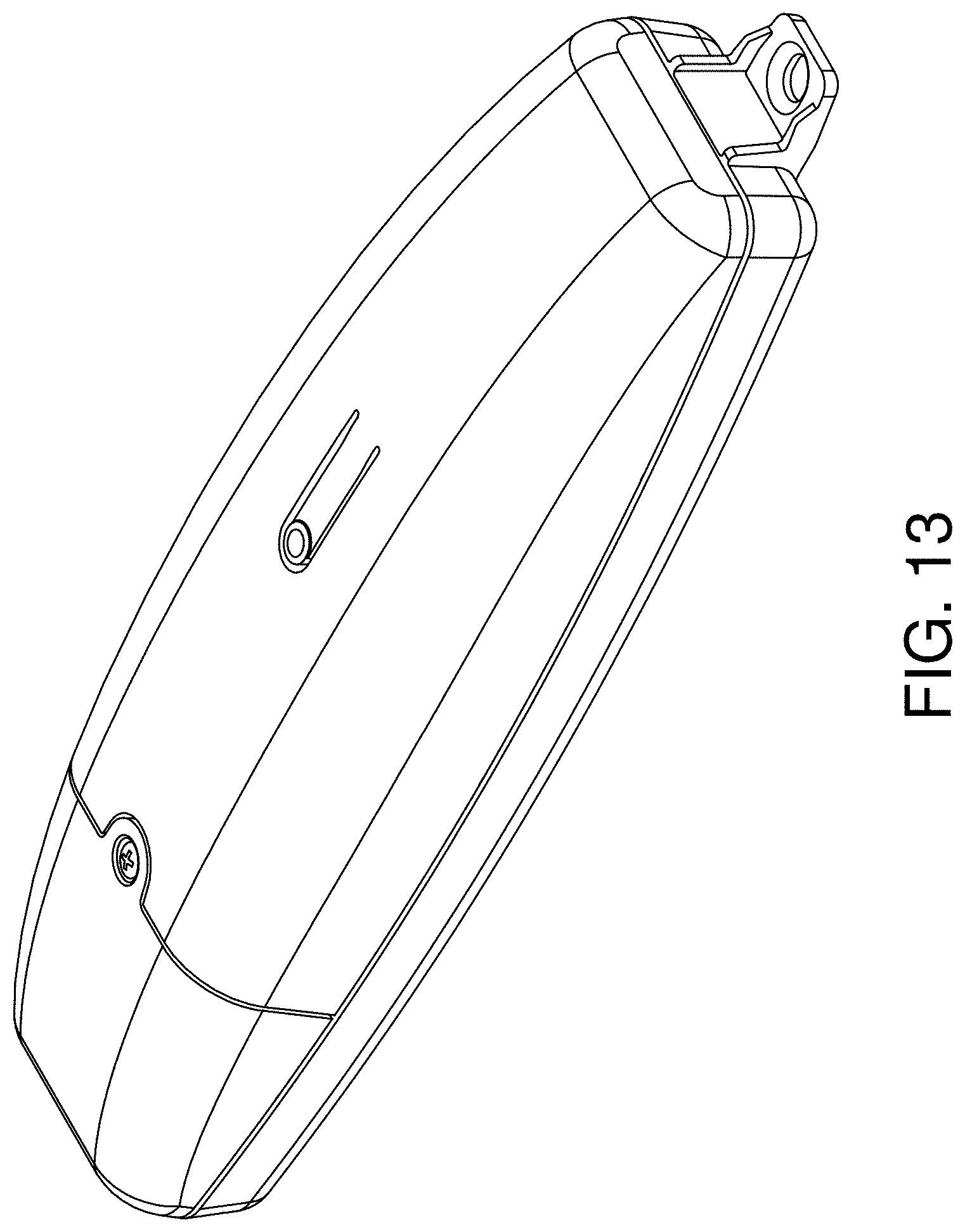
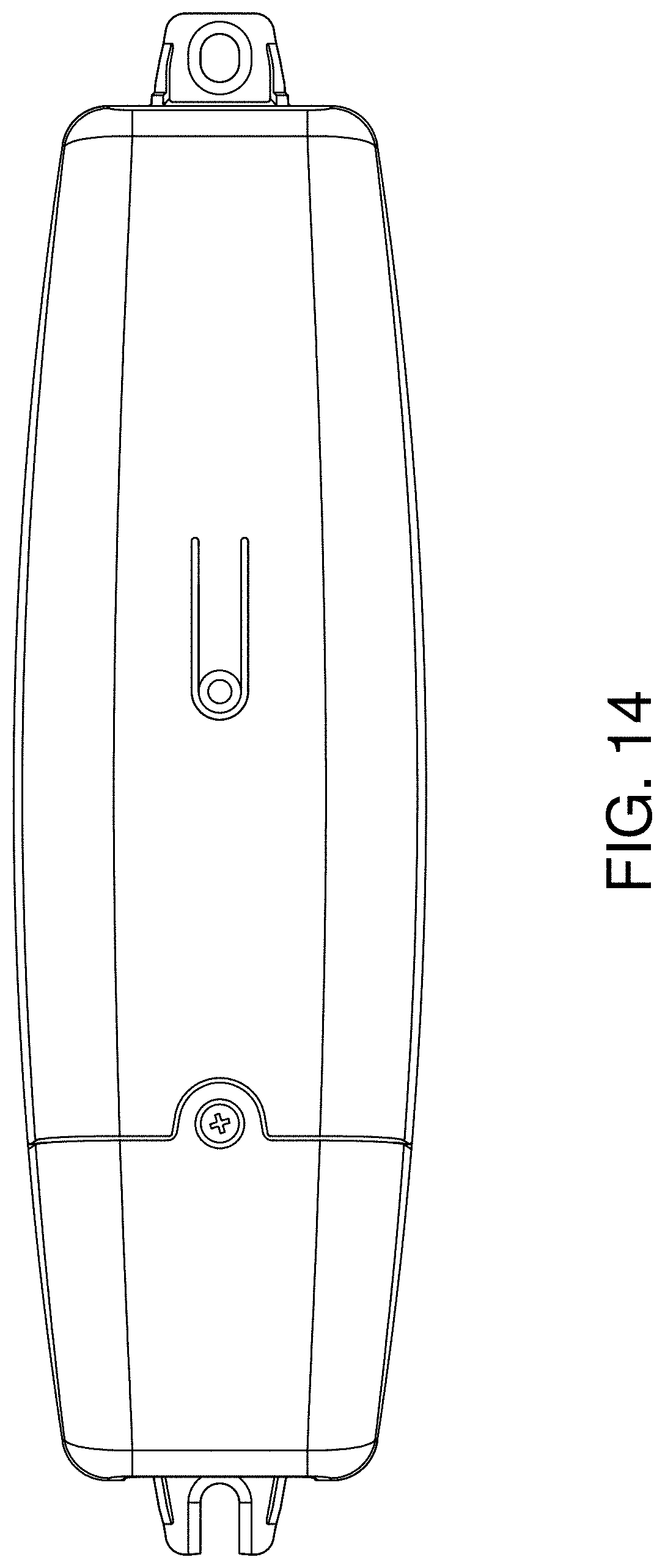
FIG. 13 is a front perspective view of a third embodiment thereof.
FIG. 14 is a front view thereof.
FIG. 15 is a left side view thereof.
FIG. 16 is a right side view thereof.
FIG. 17 is a top view thereof;
FIG. 18 is a bottom view thereof.
FIG. 19 is a front perspective view of a fourth embodiment thereof.
FIG. 20 is a front view thereof.
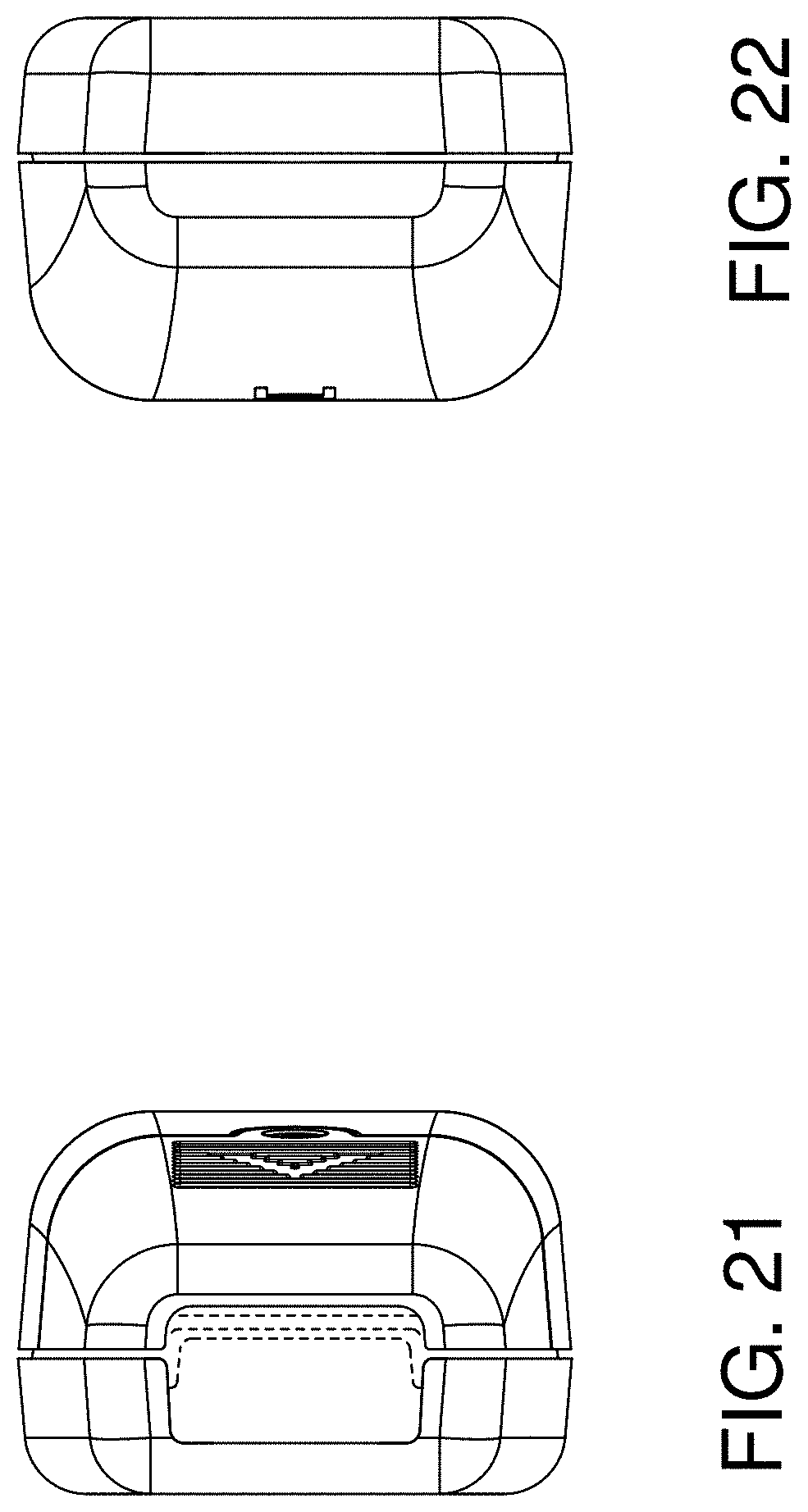
FIG. 21 is a left side view thereof.
FIG. 22 is a right side view thereof.
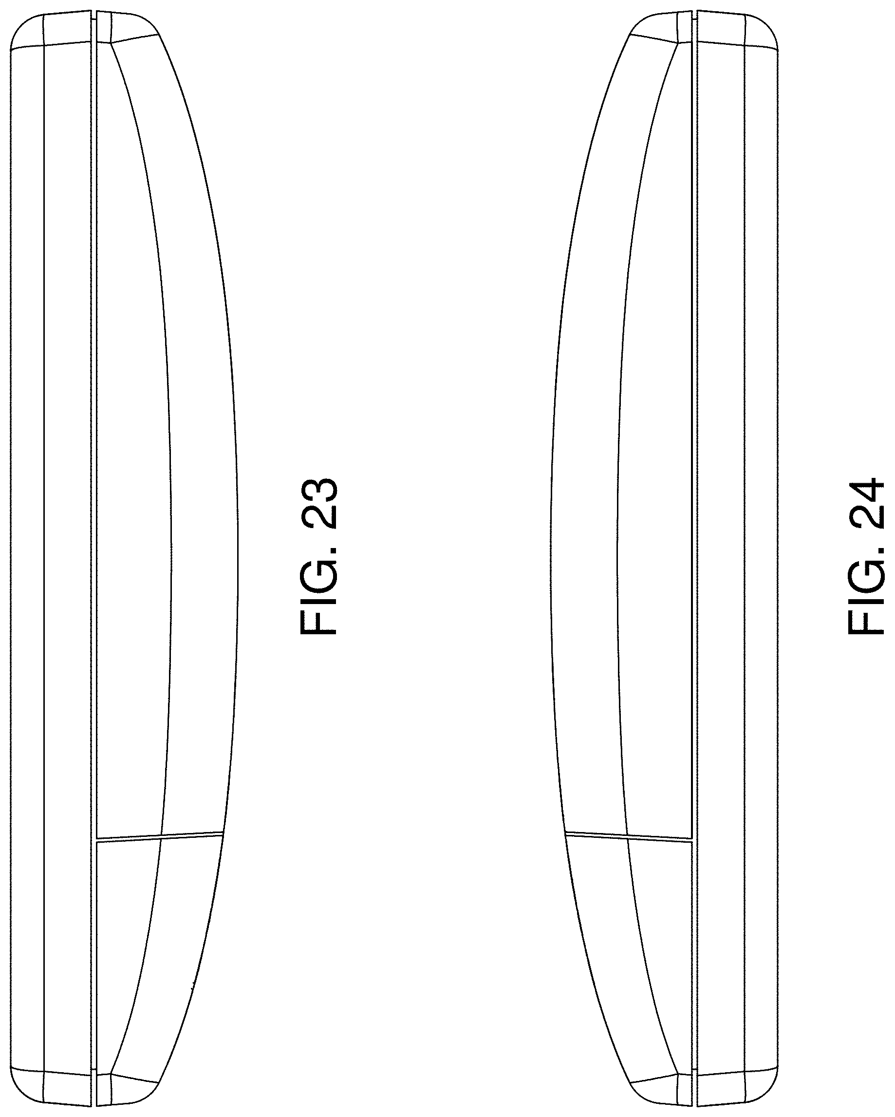
FIG. 23 is a top view thereof.
FIG. 24 is a bottom view thereof.
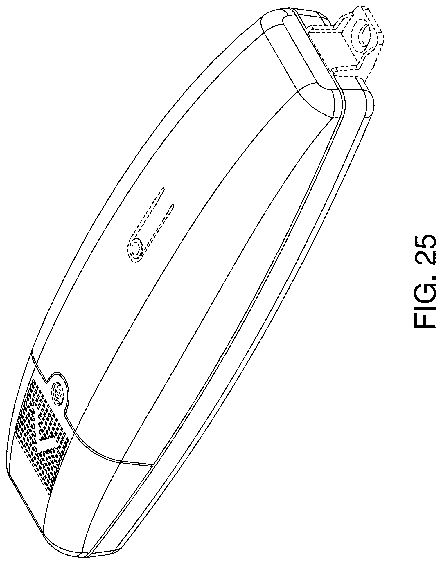
FIG. 25 is a front perspective view of a fifth embodiment thereof.
FIG. 26 is a front view thereof.
FIG. 27 is a left side view thereof.
FIG. 28 is a right side view thereof.
FIG. 29 is a top view thereof.
FIG. 30 is a bottom view thereof.
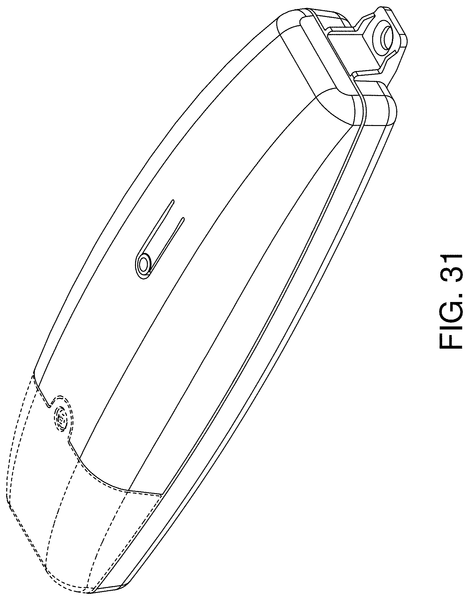
FIG. 31 is a front perspective view of a sixth embodiment thereof.
FIG. 32 is a front view thereof.
FIG. 33 is a left side view thereof.
FIG. 34 is a right side view thereof.
FIG. 35 is a top view thereof; and,
FIG. 36 is a bottom view thereof.
The rear views form no part of the claimed design and are omitted.
The uniform dashed broken lines illustrate structure or features which form no part of the claimed design.
* * * * *
References
D00000
D00001
D00002
D00003
D00004
D00005
D00006
D00007
D00008
D00009
D00010
D00011
D00012

D00013

D00014

D00015
D00016
D00017
D00018

D00019

D00020

D00021
D00022

D00023

D00024

XML
uspto.report is an independent third-party trademark research tool that is not affiliated, endorsed, or sponsored by the United States Patent and Trademark Office (USPTO) or any other governmental organization. The information provided by uspto.report is based on publicly available data at the time of writing and is intended for informational purposes only.
While we strive to provide accurate and up-to-date information, we do not guarantee the accuracy, completeness, reliability, or suitability of the information displayed on this site. The use of this site is at your own risk. Any reliance you place on such information is therefore strictly at your own risk.
All official trademark data, including owner information, should be verified by visiting the official USPTO website at www.uspto.gov. This site is not intended to replace professional legal advice and should not be used as a substitute for consulting with a legal professional who is knowledgeable about trademark law.