Riser for a television antenna
Snyker , et al. Dec
U.S. patent number D871,379 [Application Number D/595,355] was granted by the patent office on 2019-12-31 for riser for a television antenna. This patent grant is currently assigned to Electronic Controlled Systems, Inc.. The grantee listed for this patent is Electronic Controlled Systems, Inc.. Invention is credited to Paul Bruzek, Craig Miller, Mark Snyker.


| United States Patent | D871,379 |
| Snyker , et al. | December 31, 2019 |
Riser for a television antenna
Claims
CLAIM We claim an ornamental design for a riser for a television antenna, as shown and described.
| Inventors: | Snyker; Mark (Shakopee, MN), Bruzek; Paul (Minneapolis, MN), Miller; Craig (Eden Prairie, MN) | ||||||||||
|---|---|---|---|---|---|---|---|---|---|---|---|
| Applicant: |
|
||||||||||
| Assignee: | Electronic Controlled Systems,
Inc. (Bloomington, MN) |
||||||||||
| Appl. No.: | D/595,355 | ||||||||||
| Filed: | February 27, 2017 |
| Current U.S. Class: | D14/238 |
| Current International Class: | 1403 |
| Field of Search: | ;D14/137,138,230-238,299,358 |
References Cited [Referenced By]
U.S. Patent Documents
| 4794399 | December 1988 | Sensibaugh |
| D334570 | April 1993 | Wingard |
| D401245 | November 1998 | Benn |
| D500754 | January 2005 | Dierkes |
| D515559 | February 2006 | Dierkes |
| D519992 | May 2006 | McAnally |
| D696231 | December 2013 | Konishi |
| D827622 | September 2018 | Baiz |
| D843357 | March 2019 | Young |
Other References
|
Amazon, King OA8500 Jack HDTV Directional Over-the-Air Antenna with Mount and Signal Finder , Nov. 30, 2016, https://www.amazon.com/dp/B01N1MLFGK/ref=psdc_172665_t1_B01MTF8NKO (Year: 2016). cited by examiner. |
Primary Examiner: Hallmark; Janice
Assistant Examiner: Blackwell, II; Harold E
Attorney, Agent or Firm: Skaar Ulbrich Macari, P.A.
Description
FIG. 1 is a perspective view of a riser for a television antenna showing the claimed design;
FIG. 2 is another perspective view thereof;
FIG. 3 is a front elevational view thereof;
FIG. 4 is a rear elevational view thereof;
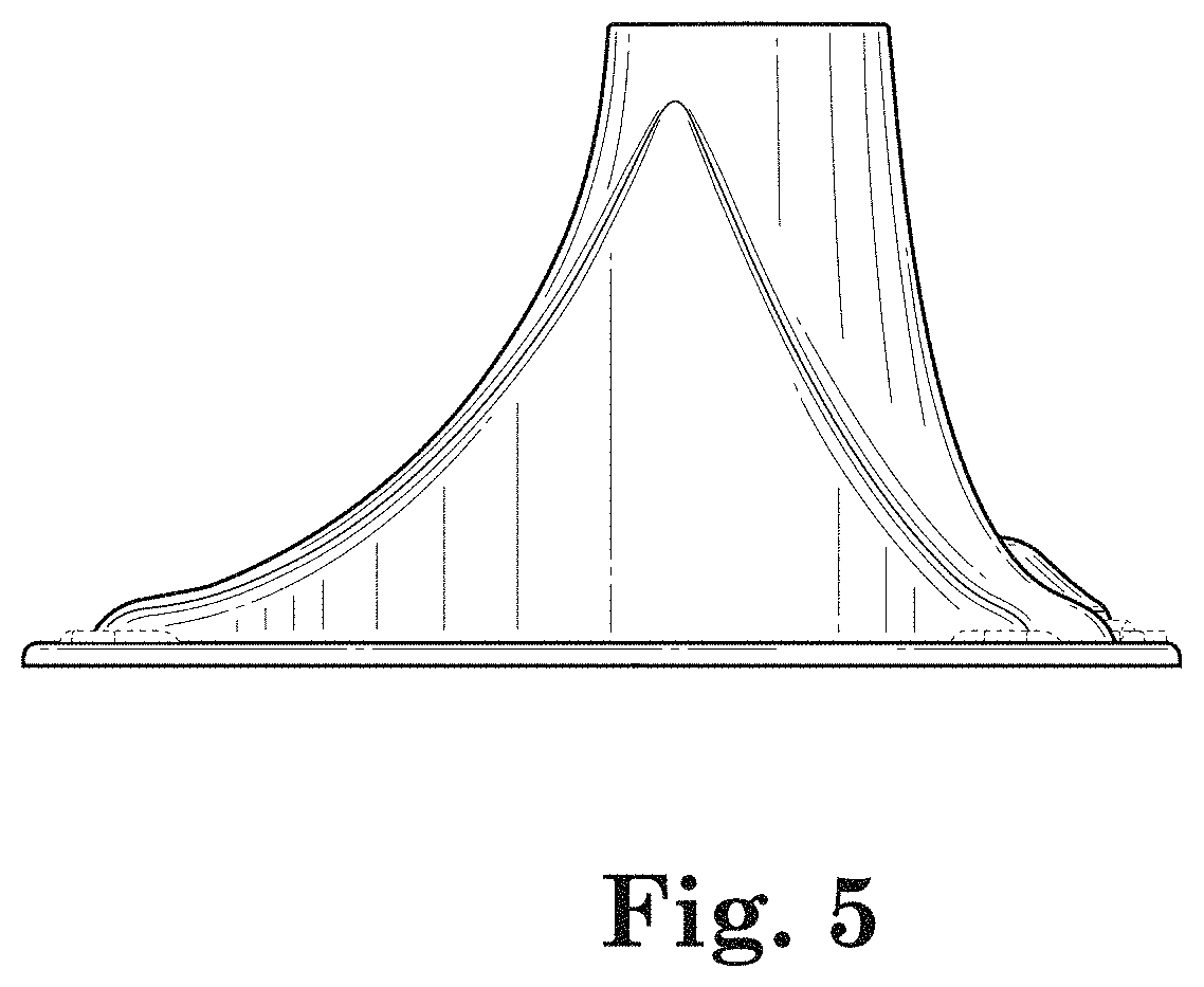
FIG. 5 is a first side elevational view thereof
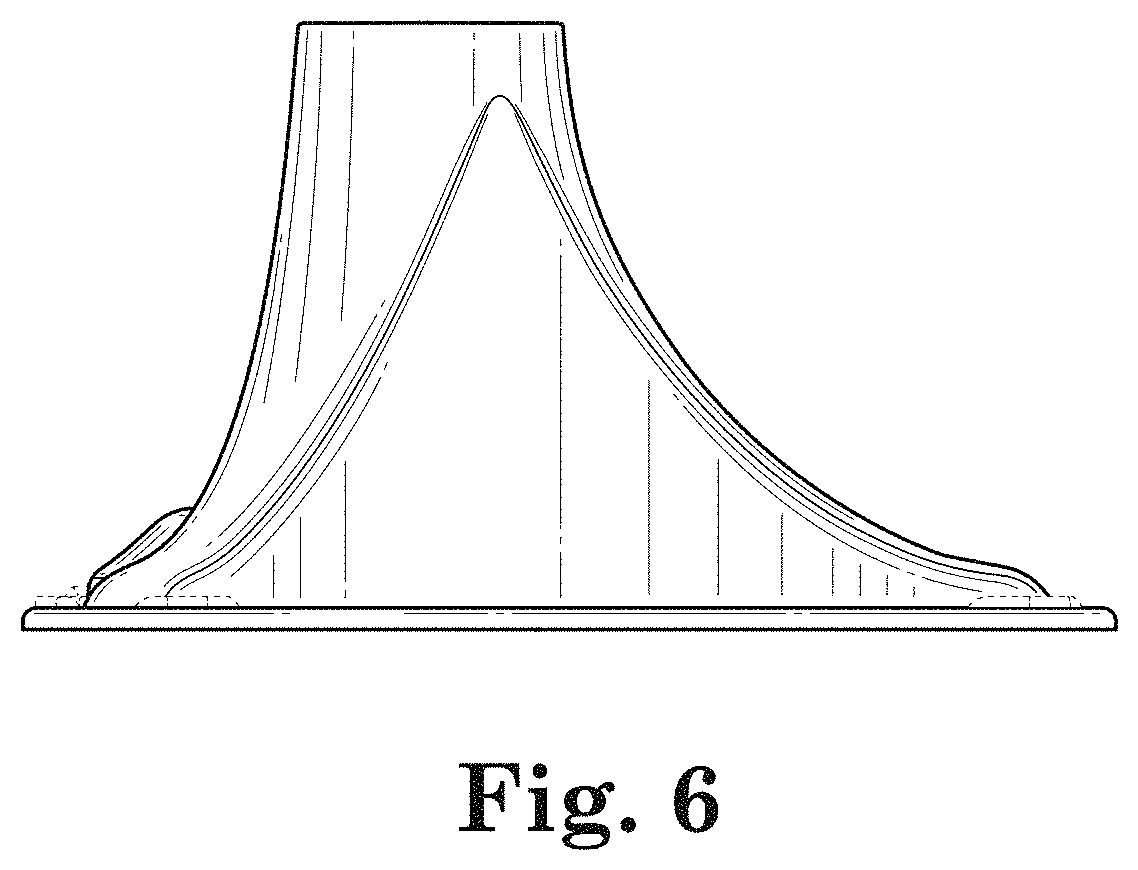
FIG. 6 is a second side elevational view thereof, the second side being the opposite side of that shown in FIG. 5;
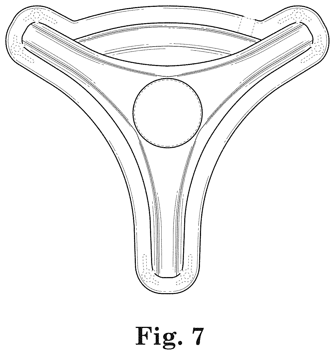
FIG. 7 is a top plan view thereof; and,
FIG. 8 is a bottom plan view thereof.
The broken lines in the figures represent portions of the article which form no part of the claimed design.
* * * * *
References
D00000
D00001
D00002
D00003
D00004
D00005
D00006
D00007
D00008
XML
uspto.report is an independent third-party trademark research tool that is not affiliated, endorsed, or sponsored by the United States Patent and Trademark Office (USPTO) or any other governmental organization. The information provided by uspto.report is based on publicly available data at the time of writing and is intended for informational purposes only.
While we strive to provide accurate and up-to-date information, we do not guarantee the accuracy, completeness, reliability, or suitability of the information displayed on this site. The use of this site is at your own risk. Any reliance you place on such information is therefore strictly at your own risk.
All official trademark data, including owner information, should be verified by visiting the official USPTO website at www.uspto.gov. This site is not intended to replace professional legal advice and should not be used as a substitute for consulting with a legal professional who is knowledgeable about trademark law.