Pressure washer frame
Alexander Dec
U.S. patent number D870,411 [Application Number D/694,808] was granted by the patent office on 2019-12-17 for pressure washer frame. This patent grant is currently assigned to FNA GROUP, INC.. The grantee listed for this patent is FNA Group, Inc.. Invention is credited to Gus Alexander.


| United States Patent | D870,411 |
| Alexander | December 17, 2019 |
Pressure washer frame
Claims
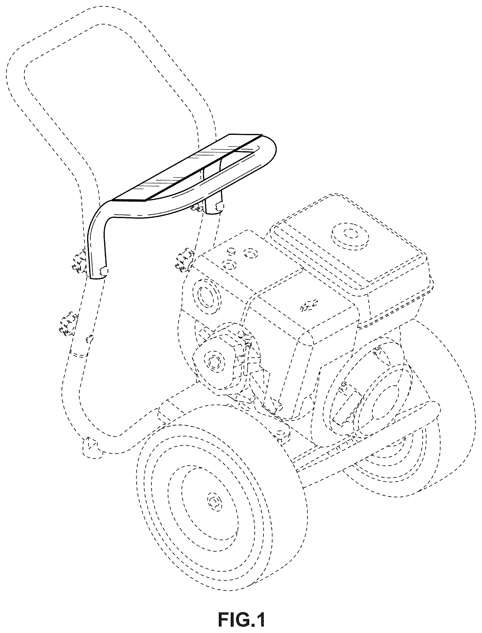
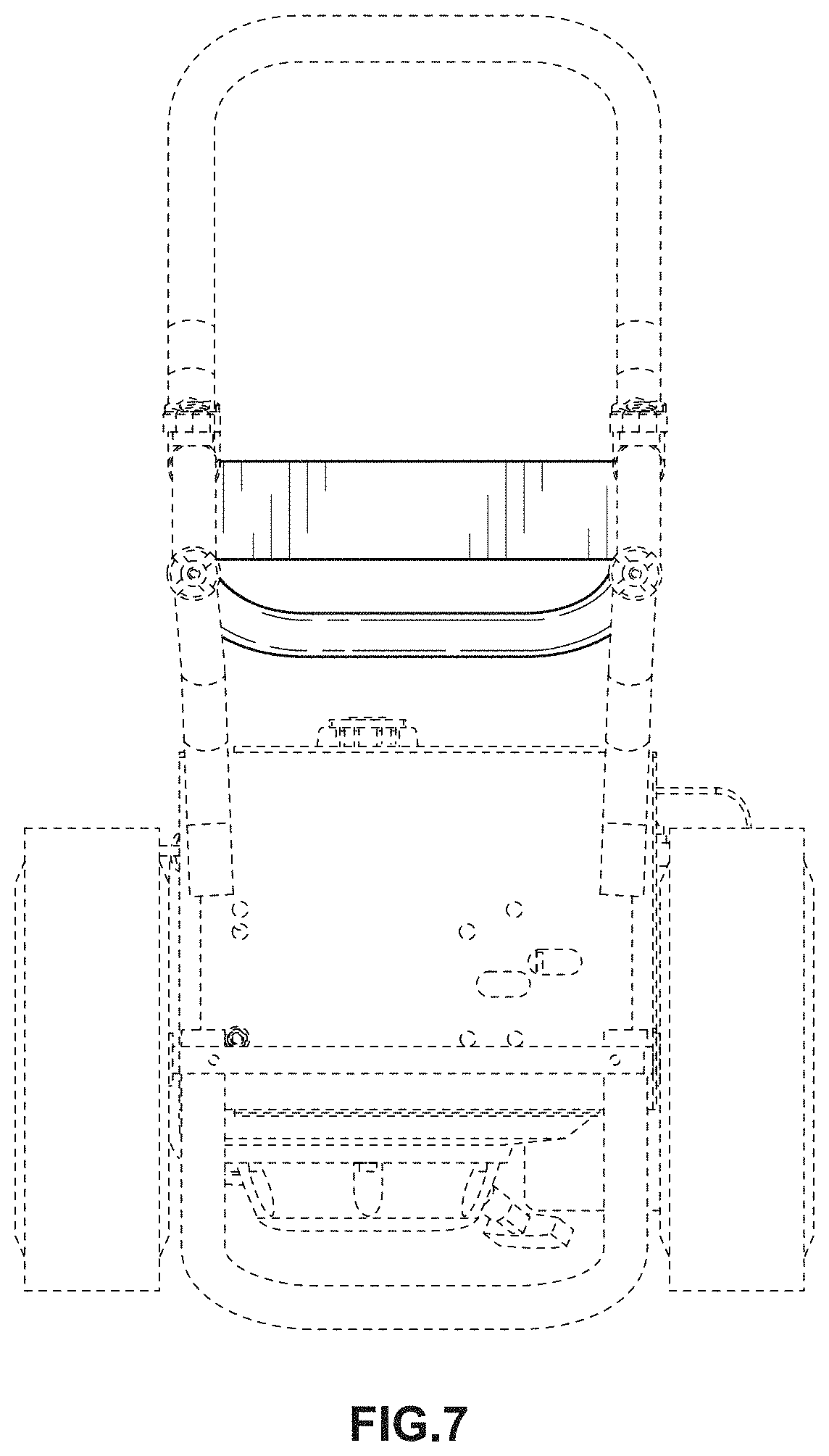
CLAIM I claim the ornamental design for a pressure washer frame, as shown and described.
| Inventors: | Alexander; Gus (Inverness, IL) | ||||||||||
|---|---|---|---|---|---|---|---|---|---|---|---|
| Applicant: |
|
||||||||||
| Assignee: | FNA GROUP, INC. (Pleasant
Prairie, WI) |
||||||||||
| Appl. No.: | D/694,808 | ||||||||||
| Filed: | June 13, 2019 |
Related U.S. Patent Documents
| Application Number | Filing Date | Patent Number | Issue Date | ||
|---|---|---|---|---|---|
| 29598855 | Mar 29, 2017 | D854763 | |||
| Current U.S. Class: | D34/24 |
| Current International Class: | 1202 |
| Field of Search: | ;D32/15-16,25 ;D34/24,12,14 ;280/47.131 |
References Cited [Referenced By]
U.S. Patent Documents
| D402433 | December 1998 | Wells |
| D580610 | November 2008 | Hawkins |
| D590110 | April 2009 | Hawkins |
| D596817 | July 2009 | Glass |
| D622471 | August 2010 | Hernandez |
| D648082 | November 2011 | Alexander |
| D688841 | August 2013 | van Deursen |
| 8602323 | December 2013 | Bearup |
| D702900 | April 2014 | Kahan |
| D703888 | April 2014 | Kahan |
| D733373 | June 2015 | Kahan |
| D824612 | July 2018 | Alexander |
| D824613 | July 2018 | Alexander |
Other References
|
United States Patent and Trademark Office, "Notice of Allowance and Fee(s) Due," issued in connection with U.S. Design Appl. No. 29/694,804, dated Aug. 14, 2019, 16 pages. cited by applicant. |
Primary Examiner: McInroy; Ruth
Attorney, Agent or Firm: Hanley, Flight & Zimmerman, LLC
Description
FIG. 1 is a front, top perspective view of a pressure washer frame.
FIG. 2 is a front view of the pressure washer frame of FIG. 1.
FIG. 3 is a rear view of the pressure washer frame of FIG. 1.
FIG. 4 is a left side view of the pressure washer frame of FIG. 1.
FIG. 5 is a right side view of the pressure washer frame of FIG. 1.
FIG. 6 is a top view of the pressure washer frame of FIG. 1; and,
FIG. 7 is a bottom view of the pressure washer frame of FIG. 1.
The features shown in broken lines form no part of the claimed design.
* * * * *
D00000
D00001
D00002
D00003
D00004
D00005
D00006
D00007
XML
uspto.report is an independent third-party trademark research tool that is not affiliated, endorsed, or sponsored by the United States Patent and Trademark Office (USPTO) or any other governmental organization. The information provided by uspto.report is based on publicly available data at the time of writing and is intended for informational purposes only.
While we strive to provide accurate and up-to-date information, we do not guarantee the accuracy, completeness, reliability, or suitability of the information displayed on this site. The use of this site is at your own risk. Any reliance you place on such information is therefore strictly at your own risk.
All official trademark data, including owner information, should be verified by visiting the official USPTO website at www.uspto.gov. This site is not intended to replace professional legal advice and should not be used as a substitute for consulting with a legal professional who is knowledgeable about trademark law.