Vehicle tail lamp
Dewitt , et al. De
U.S. patent number D869,018 [Application Number D/632,605] was granted by the patent office on 2019-12-03 for vehicle tail lamp. This patent grant is currently assigned to Ford Global Technologies, LLC. The grantee listed for this patent is Ford Global Technologies, LLC. Invention is credited to David Dewitt, Pedro Guarinon, Todd Willing, Max Wolff, Mark Wright.


View All Diagrams
| United States Patent | D869,018 |
| Dewitt , et al. | December 3, 2019 |
Vehicle tail lamp
Claims
CLAIM The ornamental design for a vehicle tail lamp, as shown and described.
| Inventors: | Dewitt; David (Docklands, AU), Willing; Todd (East Melbourne, AU), Wolff; Max (Birmingham, MI), Guarinon; Pedro (Melbourne, AU), Wright; Mark (Nunawading, AU) | ||||||||||
|---|---|---|---|---|---|---|---|---|---|---|---|
| Applicant: |
|
||||||||||
| Assignee: | Ford Global Technologies, LLC
(Dearborn, MI) |
||||||||||
| Appl. No.: | D/632,605 | ||||||||||
| Filed: | January 9, 2018 |
| Current U.S. Class: | D26/28 |
| Current International Class: | 2606 |
| Field of Search: | ;D26/28-36,139 |
References Cited [Referenced By]
U.S. Patent Documents
| D592332 | May 2009 | Hsu |
| D631177 | January 2011 | Yang |
| D637320 | May 2011 | Yang |
| D731099 | June 2015 | Thole |
| D775384 | December 2016 | Lin |
| D775385 | December 2016 | Lin |
Attorney, Agent or Firm: Chea; Vichit
Description
FIG. 1 is a front elevational view of a vehicle tail lamp, showing our new design;
FIG. 2 is a rear elevational view thereof;
FIG. 3 is a left side elevational view thereof;
FIG. 4 is a right side elevational view thereof;
FIG. 5 is a top plan view thereof;
FIG. 6 is a bottom plan view thereof;
FIG. 7 is a top, front, and left side perspective view thereof; and
FIG. 8 is a bottom, front, and left side perspective view thereof.
FIG. 9 is a front elevational view of a second embodiment of a vehicle tail lamp, showing our new design;
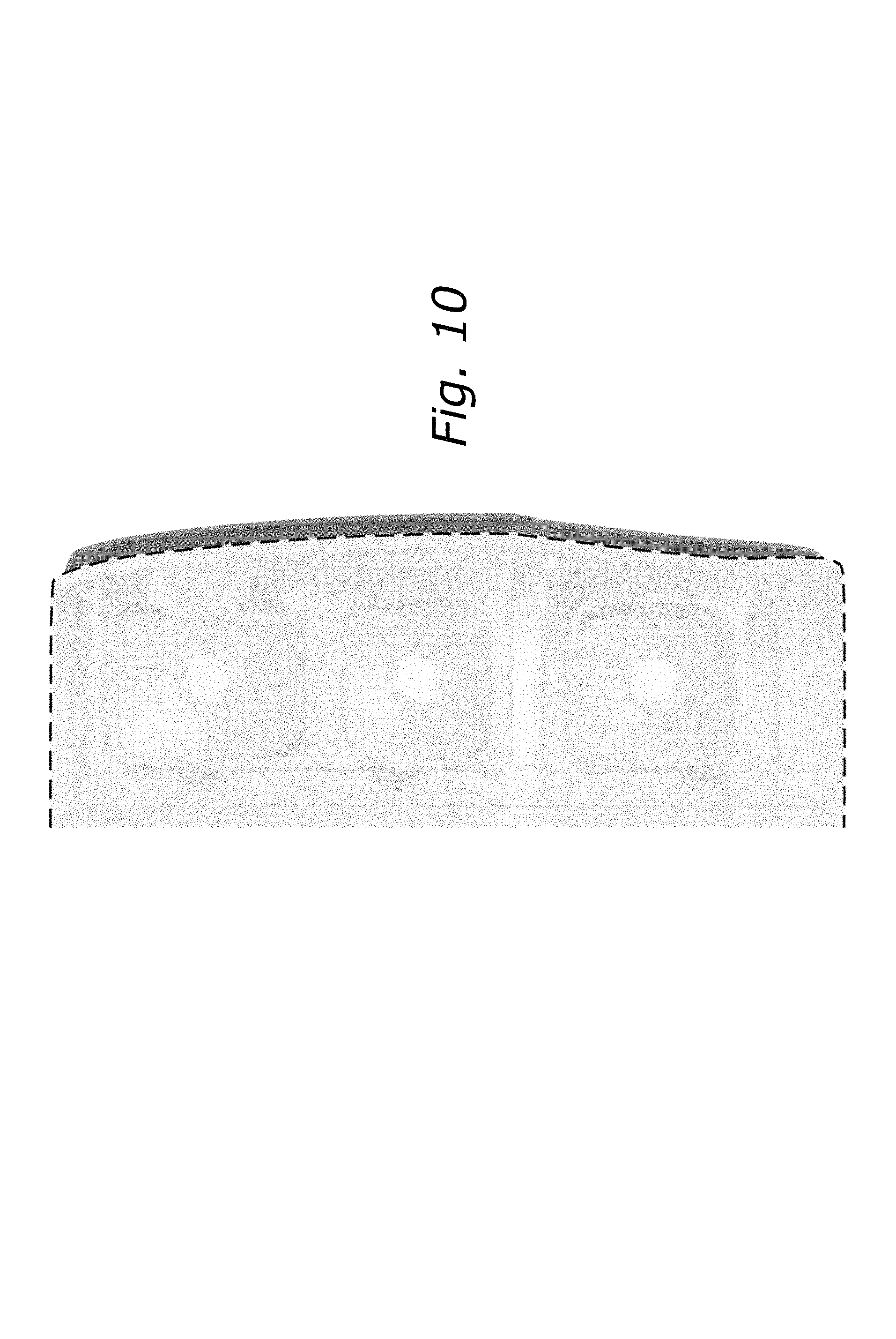
FIG. 10 is a rear elevational view thereof;
FIG. 11 is a left side elevational view thereof;
FIG. 12 is a right side elevational view thereof;
FIG. 13 is a top plan view thereof;
FIG. 14 is a bottom plan view thereof;
FIG. 15 is a top, front, and left side perspective view thereof; and
FIG. 16 is a bottom, front, and left side perspective view thereof.
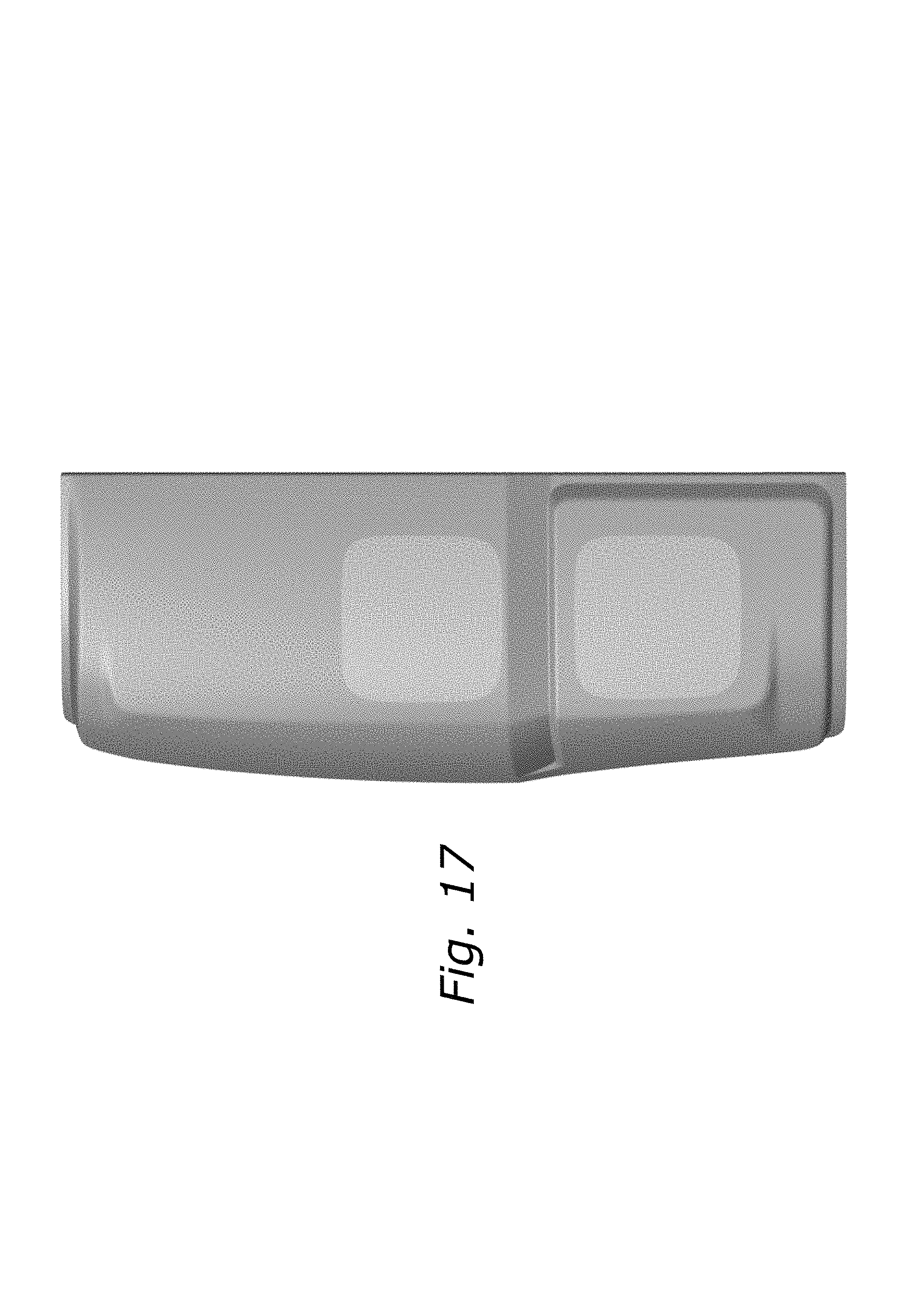
FIG. 17 is a front elevational view of a third embodiment of a vehicle tail lamp, showing our new design;
FIG. 18 is a rear elevational view thereof;
FIG. 19 is a left side elevational view thereof;
FIG. 20 is a right side elevational view thereof;
FIG. 21 is a top plan view thereof;
FIG. 22 is a bottom plan view thereof;
FIG. 23 is a top, front, and left side perspective view thereof; and
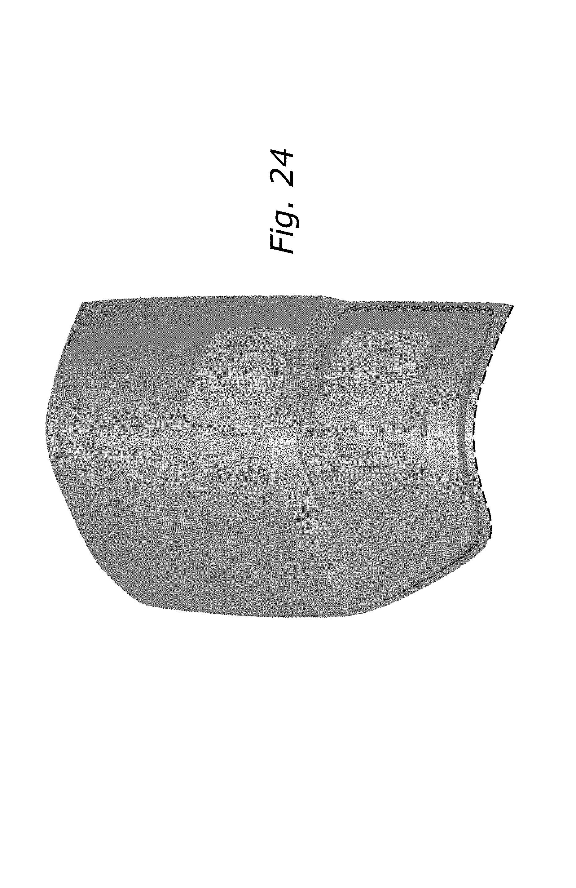
FIG. 24 is a bottom, front, and left side perspective view thereof.
FIG. 25 is a front elevational view of a forth embodiment of a vehicle tail lamp, showing our new design;
FIG. 26 is a rear elevational view thereof;
FIG. 27 is a left side elevational view thereof;
FIG. 28 is a right side elevational view thereof;
FIG. 29 is a top plan view thereof;
FIG. 30 is a bottom plan view thereof;
FIG. 31 is a top, front, and left side perspective view thereof; and
FIG. 32 is a bottom, front, and left side perspective view thereof.
FIG. 33 is a front elevational view of a fifth embodiment of a vehicle tail lamp, showing our new design;
FIG. 34 is a rear elevational view thereof;
FIG. 35 is a left side elevational view thereof;
FIG. 36 is a right side elevational view thereof;
FIG. 37 is a top plan view thereof;
FIG. 38 is a bottom plan view thereof;
FIG. 39 is a top, front, and left side perspective view thereof; and
FIG. 40 is a bottom, front, and left side perspective view thereof.
FIG. 41 is a front elevational view of a sixth embodiment of a vehicle tail lamp, showing our new design;
FIG. 42 is a rear elevational view thereof;
FIG. 43 is a left side elevational view thereof;
FIG. 44 is a right side elevational view thereof;
FIG. 45 is a top plan view thereof;
FIG. 46 is a bottom plan view thereof;
FIG. 47 is a top, front, and left side perspective view thereof; and,
FIG. 48 is a bottom, front, and left side perspective view thereof.
Any broken lines represent an internal boundry of the design; the line itself and the area within form no part of the claim.
* * * * *
D00000
D00001
D00002
D00003
D00004
D00005
D00006
D00007
D00008
D00009
D00010
D00011
D00012

D00013

D00014

D00015

D00016

D00017
D00018

D00019

D00020

D00021

D00022

D00023

D00024
D00025

D00026

D00027

D00028

D00029

D00030

D00031

D00032

D00033

D00034

D00035

D00036

D00037

D00038

D00039

D00040

D00041

D00042

D00043

D00044

D00045

D00046

D00047

D00048

XML
uspto.report is an independent third-party trademark research tool that is not affiliated, endorsed, or sponsored by the United States Patent and Trademark Office (USPTO) or any other governmental organization. The information provided by uspto.report is based on publicly available data at the time of writing and is intended for informational purposes only.
While we strive to provide accurate and up-to-date information, we do not guarantee the accuracy, completeness, reliability, or suitability of the information displayed on this site. The use of this site is at your own risk. Any reliance you place on such information is therefore strictly at your own risk.
All official trademark data, including owner information, should be verified by visiting the official USPTO website at www.uspto.gov. This site is not intended to replace professional legal advice and should not be used as a substitute for consulting with a legal professional who is knowledgeable about trademark law.