Camera system
Hodge De
U.S. patent number D868,869 [Application Number D/628,697] was granted by the patent office on 2019-12-03 for camera system. This patent grant is currently assigned to OWL CAMERAS, INC.. The grantee listed for this patent is 725-1 CORPORATION. Invention is credited to Andrew Hodge.


View All Diagrams
| United States Patent | D868,869 |
| Hodge | December 3, 2019 |
Camera system
Claims
CLAIM The ornamental design for a camera system, as shown and described.
| Inventors: | Hodge; Andrew (Palo Alto, CA) | ||||||||||
|---|---|---|---|---|---|---|---|---|---|---|---|
| Applicant: |
|
||||||||||
| Assignee: | OWL CAMERAS, INC. (Palo Alto,
CA) |
||||||||||
| Family ID: | 62023899 | ||||||||||
| Appl. No.: | D/628,697 | ||||||||||
| Filed: | December 6, 2017 |
Related U.S. Patent Documents
| Application Number | Filing Date | Patent Number | Issue Date | ||
|---|---|---|---|---|---|
| PCT/US2017/050991 | Sep 11, 2017 | ||||
| Current U.S. Class: | D16/208; D16/218 |
| Current CPC Class: | G06F16/787 20190101; H04N21/2347 20130101; G06Q40/08 20130101; G08B13/19613 20130101; H04N21/472 20130101; H04N21/21805 20130101; H04N21/44004 20130101; G06Q50/18 20130101; G11B20/0021 20130101; G08B13/19658 20130101; H04N21/21815 20130101; H04N21/2181 20130101; H04N21/4334 20130101; H04N21/6125 20130101; G08B13/19647 20130101; H04N21/4825 20130101; H04N7/181 20130101; G08B13/19684 20130101; G06F16/7837 20190101; G06K19/06009 20130101; G06K9/00771 20130101; H04N5/23245 20130101 |
| Current International Class: | 1601 |
| Field of Search: | ;D16/200,202-206,208,218,219,242 ;348/373-376 ;396/529-532,535,539-541 |
References Cited [Referenced By]
U.S. Patent Documents
| 687968 | December 1901 | Reber |
| 3259153 | July 1966 | Haase |
| 5694295 | December 1997 | Mochizuki |
| D441823 | May 2001 | Blackhurst |
| D460773 | July 2002 | Arbuckle |
| D471888 | March 2003 | Solland |
| D510198 | October 2005 | Willardson |
| D551275 | September 2007 | Kim |
| D583575 | December 2008 | Goldman |
| D625114 | October 2010 | Gouldson |
| D632097 | February 2011 | Chan |
| D661111 | June 2012 | Yau |
| D733784 | July 2015 | Yamashita |
| D747390 | January 2016 | Roth |
| D748711 | February 2016 | Roth |
| D849086 | May 2019 | Russo |
Attorney, Agent or Firm: Marton Ribera Schumann & Chang LLP Ribera; Hector J. Chuang; Chien-Ju Alice
Description
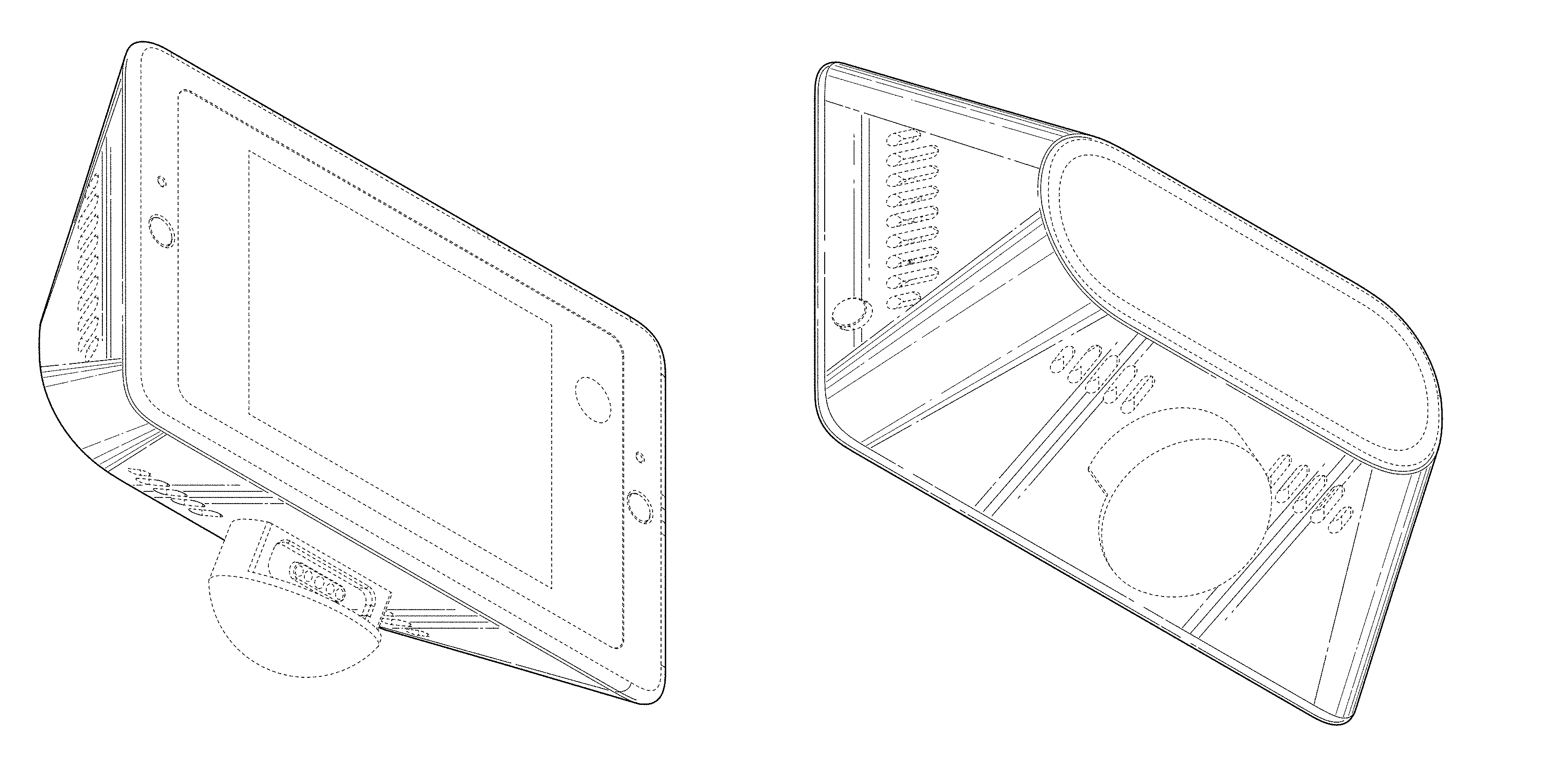
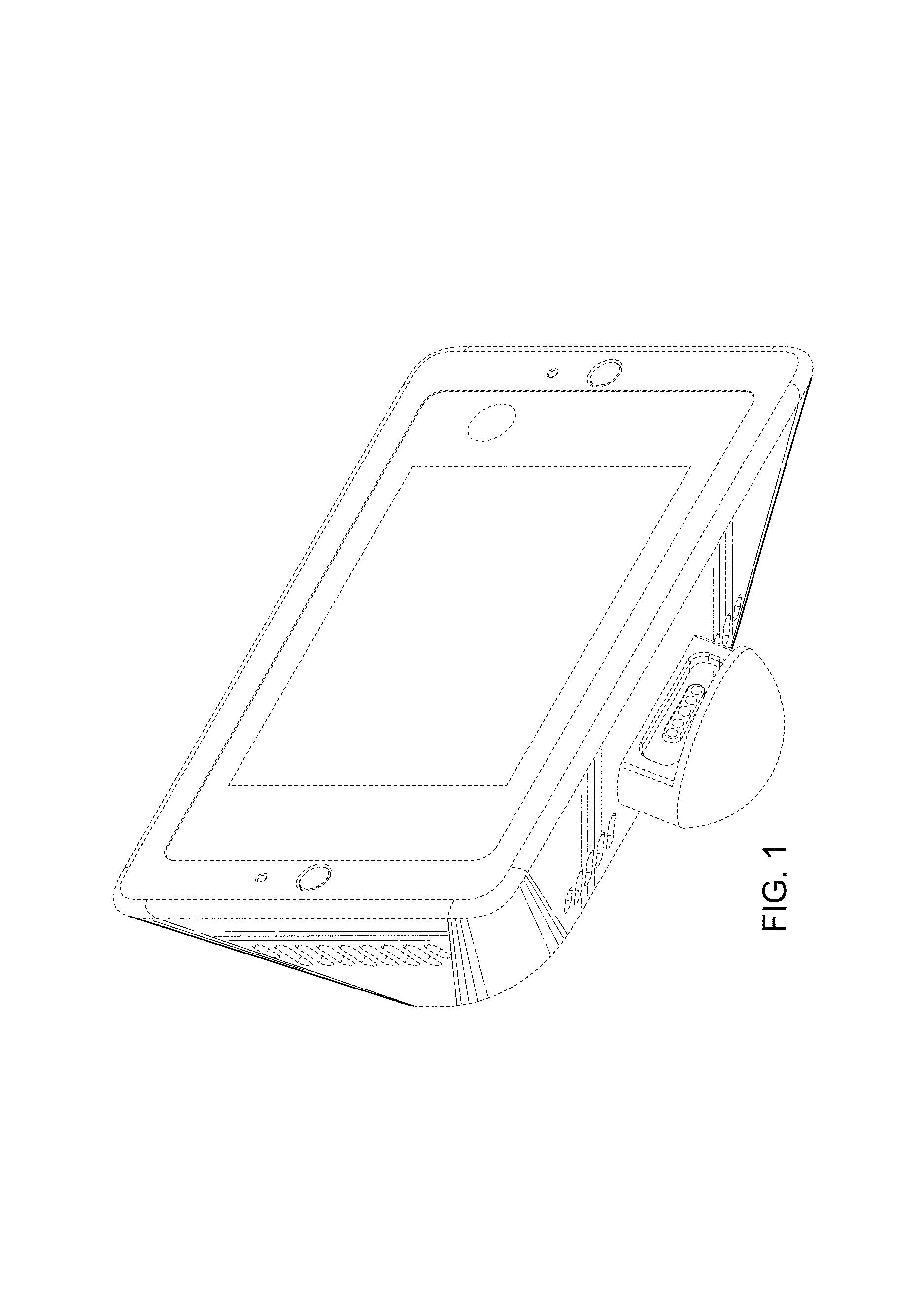
FIG. 1 is a front perspective view of a first embodiment of a camera system in accordance with the present invention.
FIG. 2 is a back perspective view of the camera system in FIG. 1.
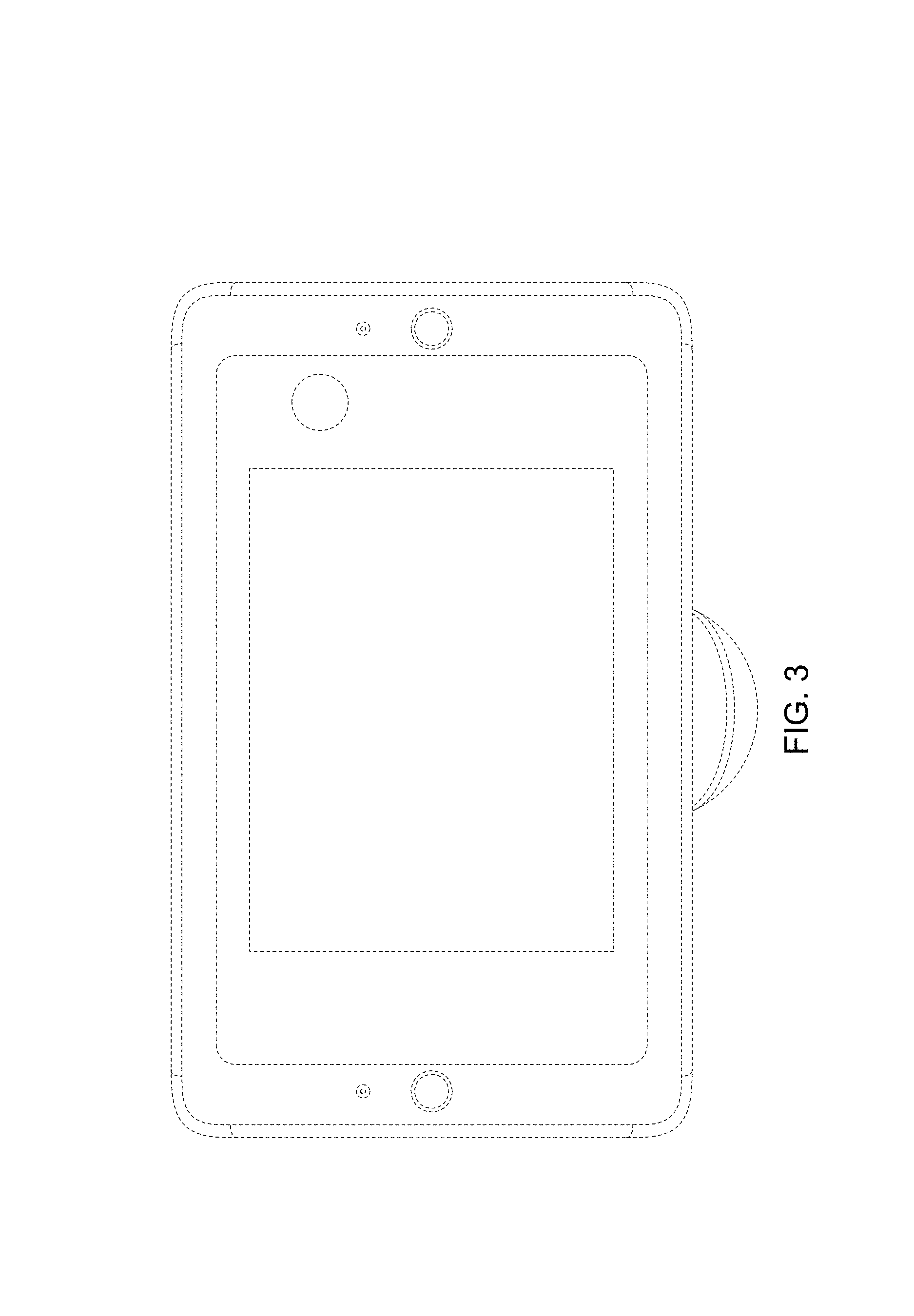
FIG. 3 is a front view of the camera system in FIG. 1.
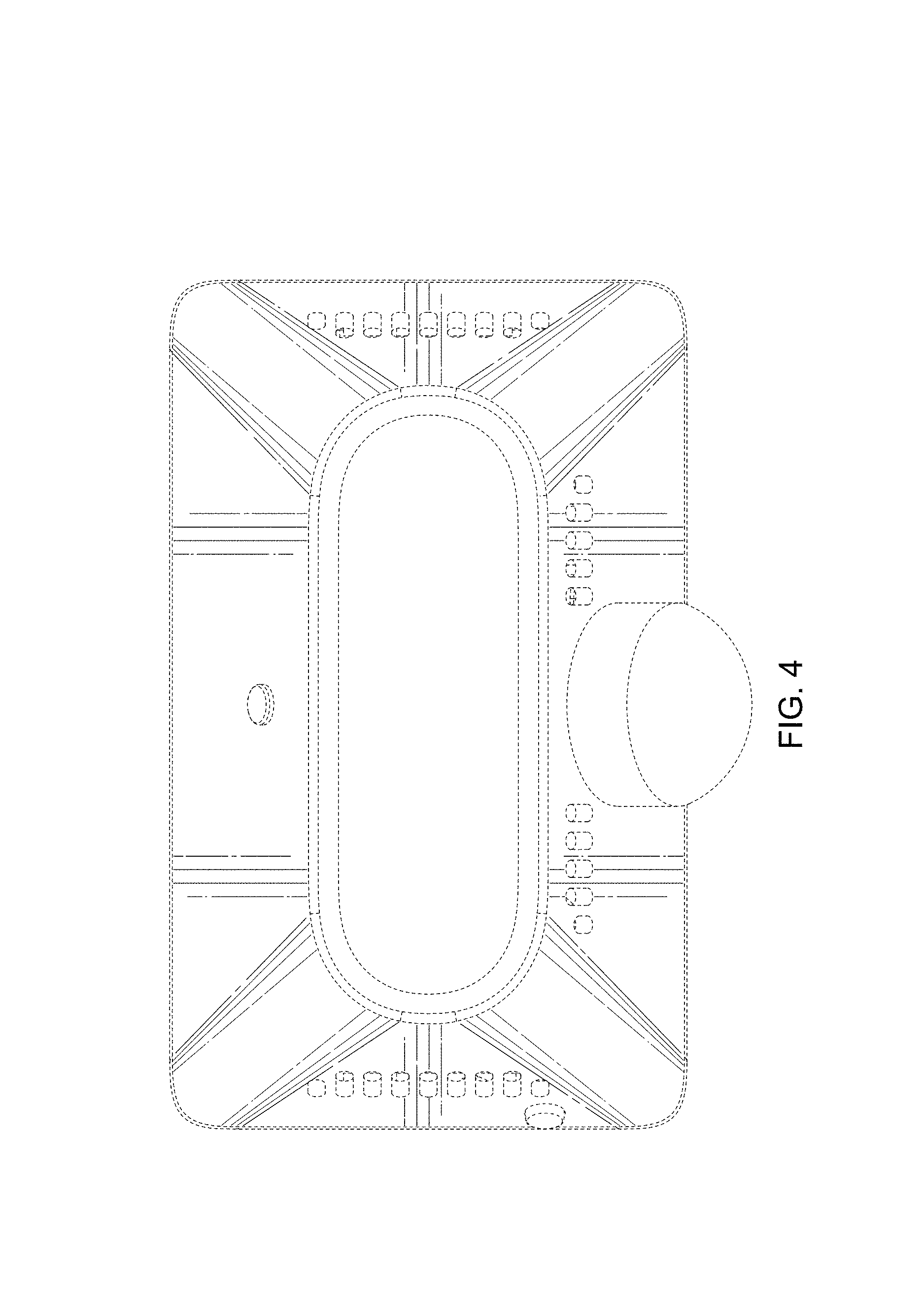
FIG. 4 is a back view of the camera system in FIG. 1.
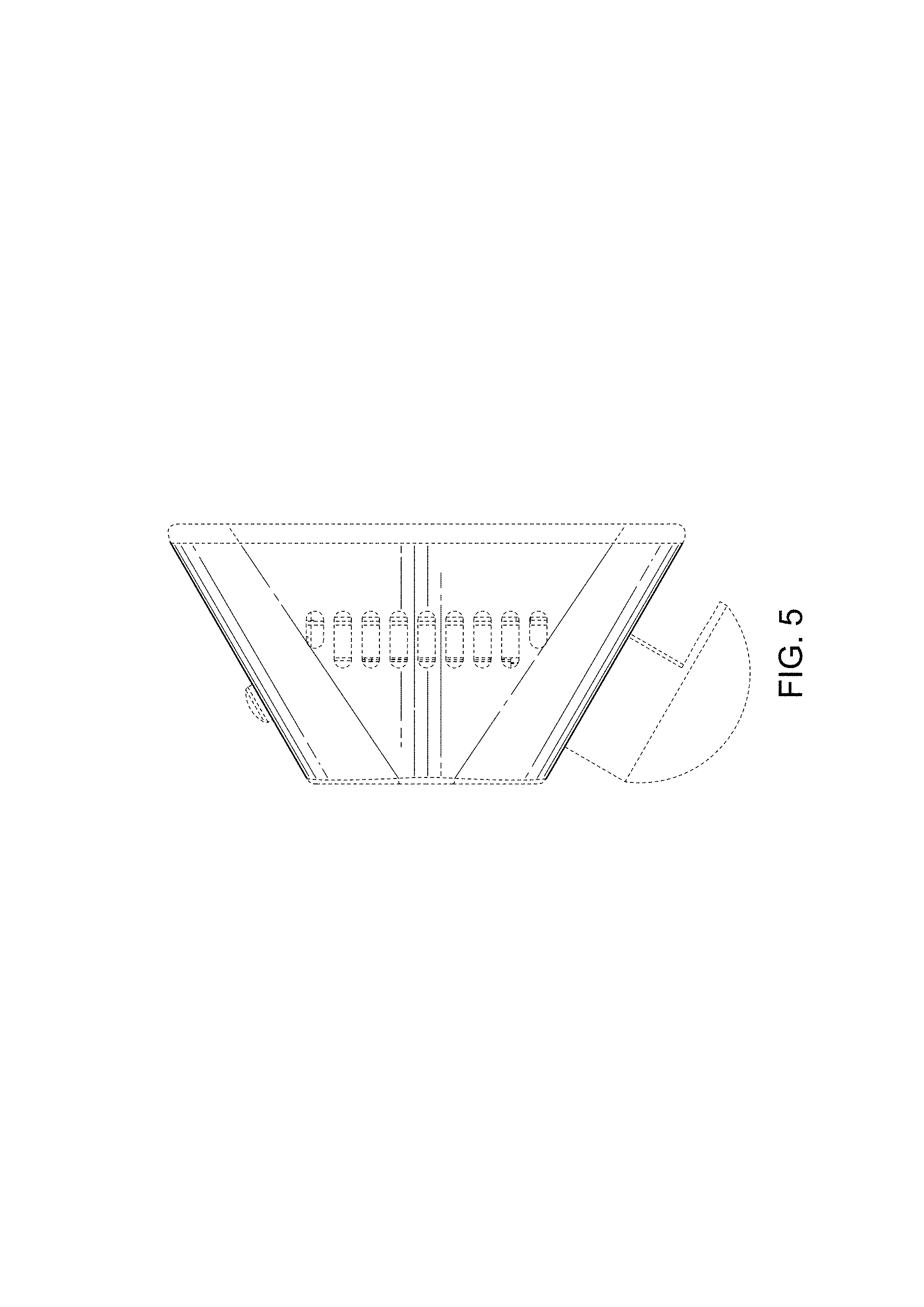
FIG. 5 is a left view of the camera system in FIG. 1.
FIG. 6 is a right view of the camera system in FIG. 1.
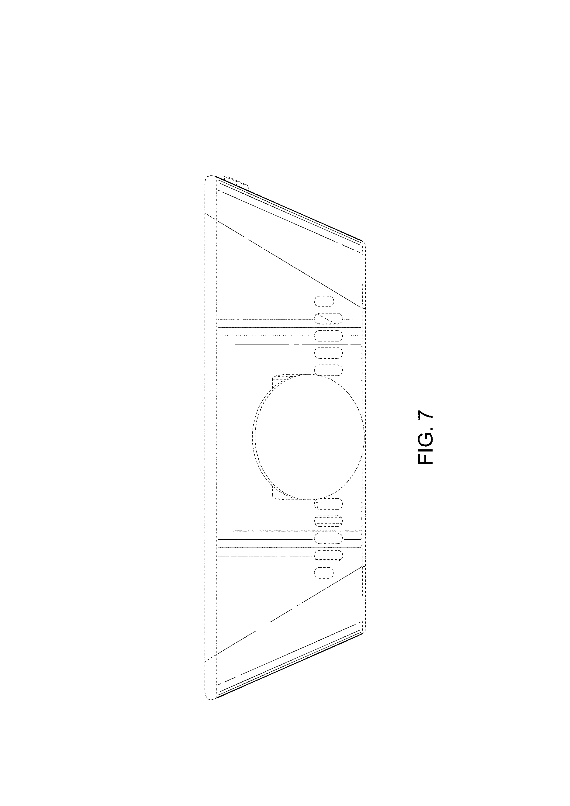
FIG. 7 is a bottom view of the camera system in FIG. 1.
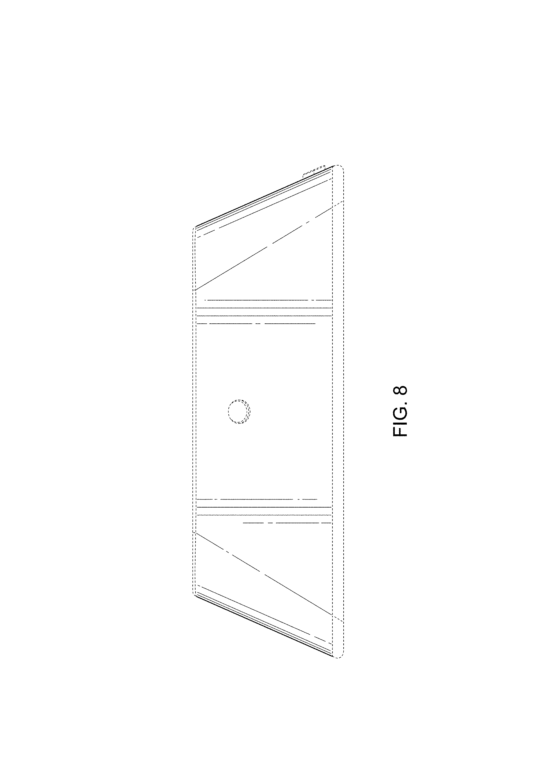
FIG. 8 is a top view of the camera system in FIG. 1.
FIG. 9 is a front perspective view of a second embodiment of a camera system in accordance with the present invention.
FIG. 10 is a back perspective view of the camera system in FIG. 9.
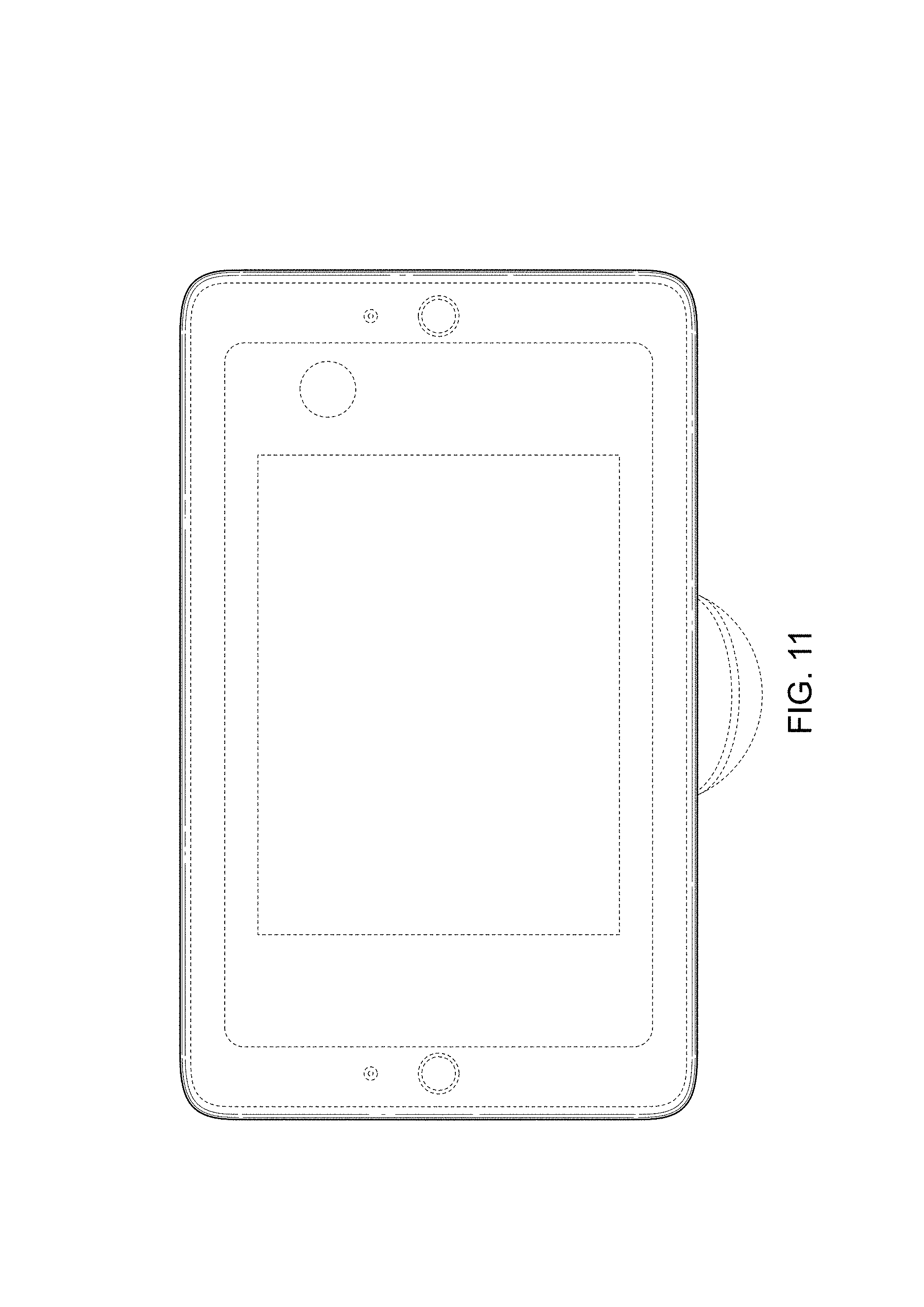
FIG. 11 is a front view of the camera system in FIG. 9.
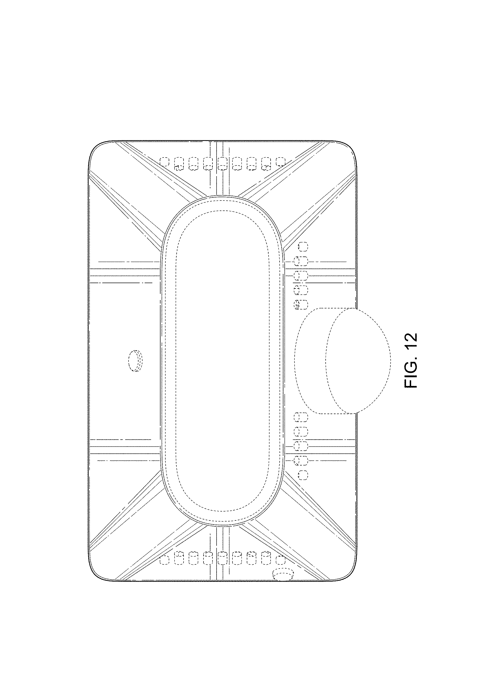
FIG. 12 is a back view of the camera system in FIG. 9.
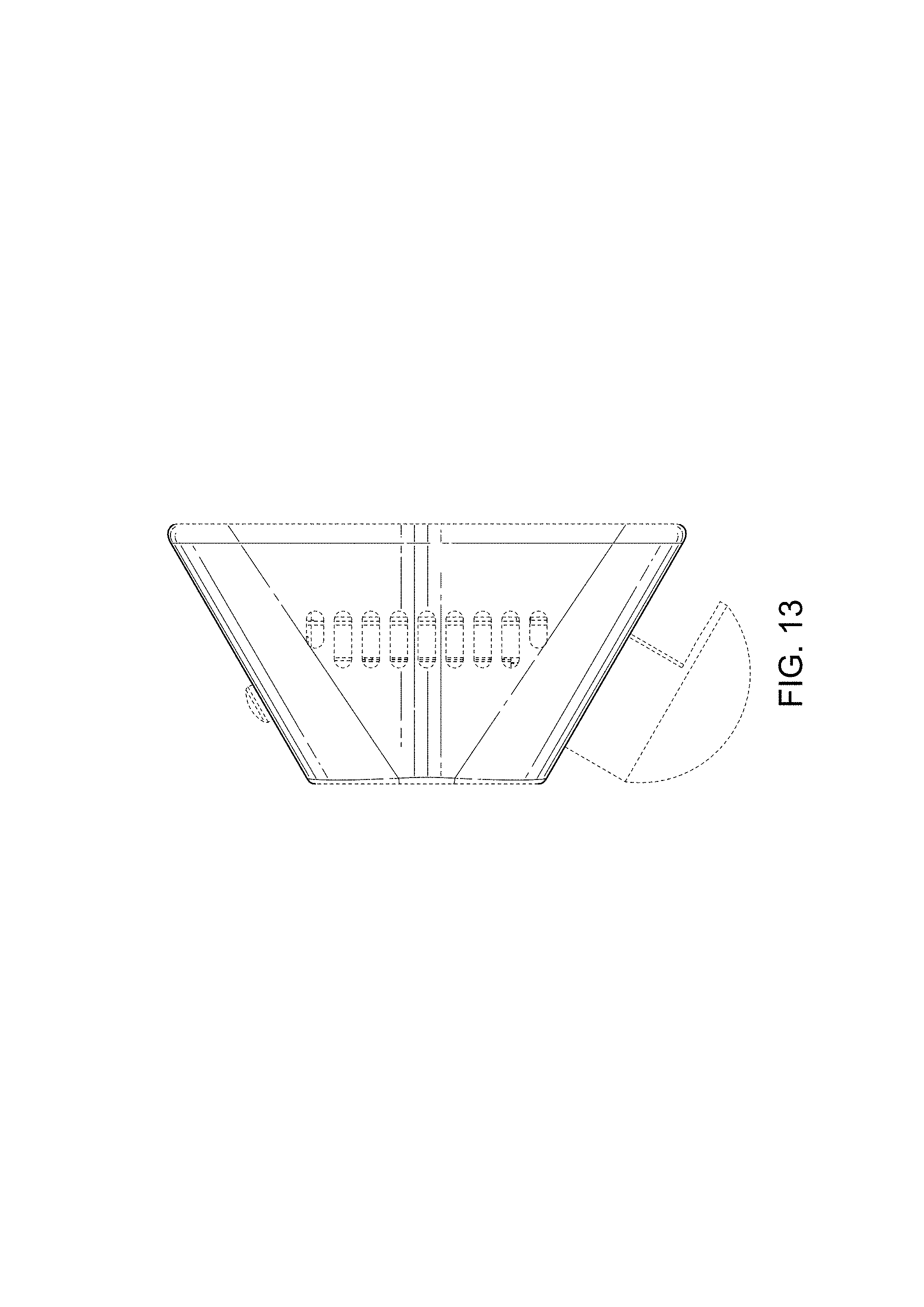
FIG. 13 is a left view of the camera system in FIG. 9.
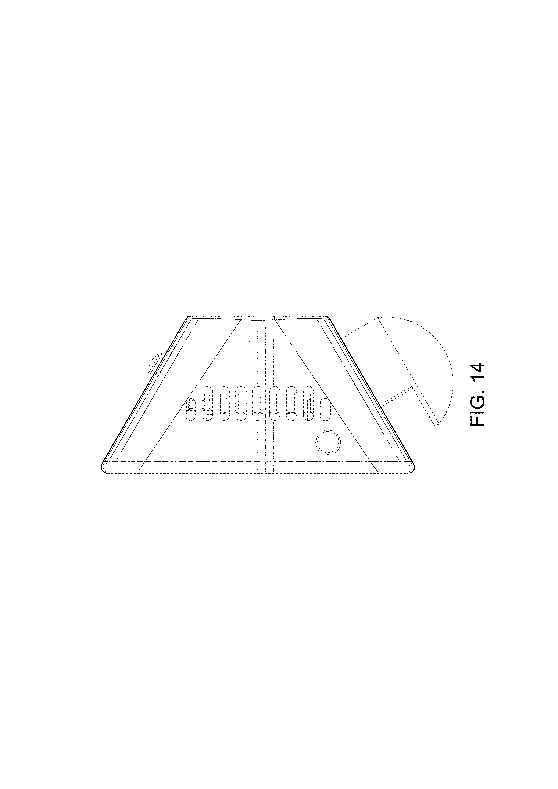
FIG. 14 is a right view of the camera system in FIG. 9.
FIG. 15 is a bottom view of the camera system in FIG. 9; and,
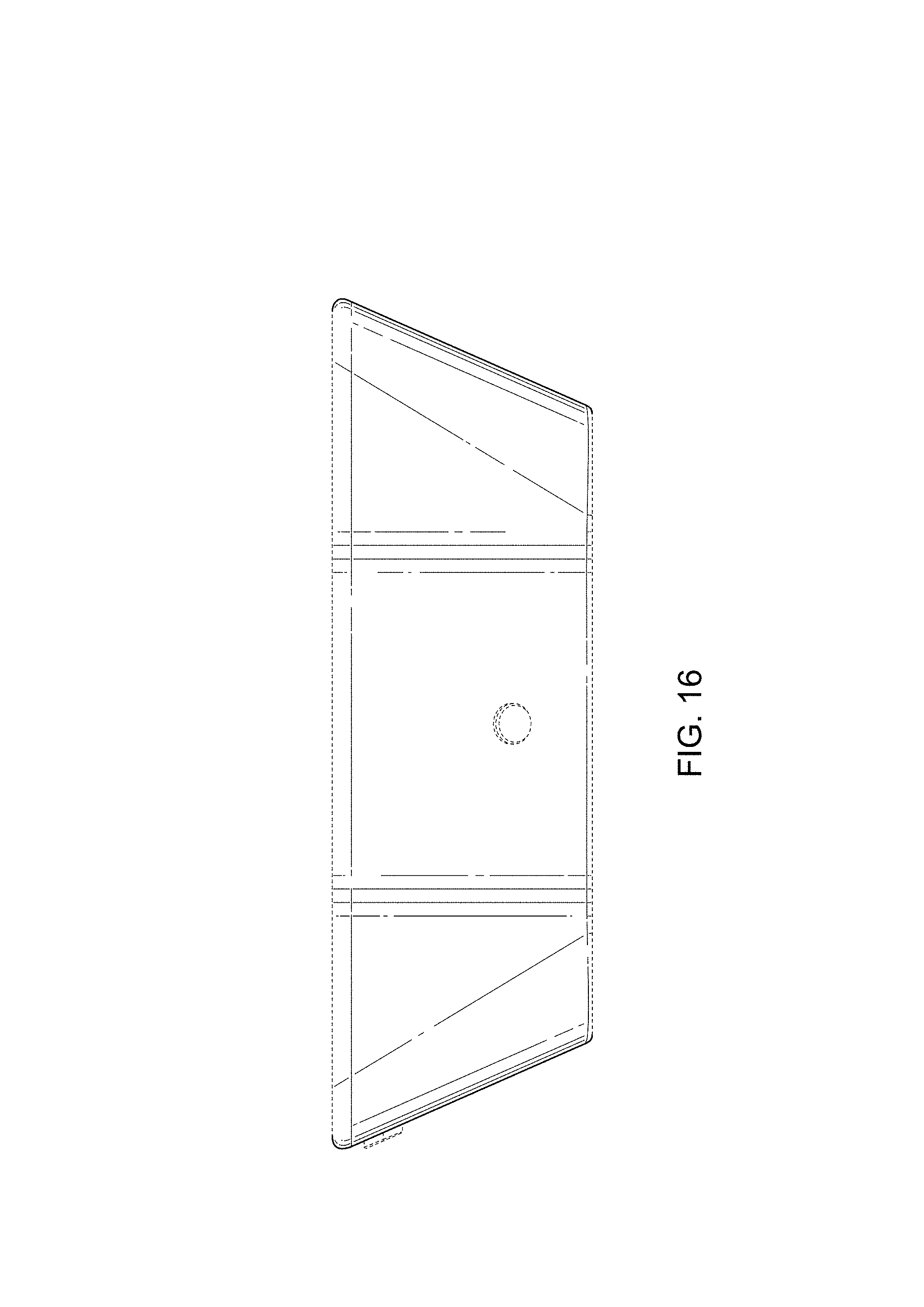
FIG. 16 is a top view of the camera system in FIG. 9.
The broken lines depict portions of the camera system in which the design is embodied that form no part of the claimed design.
* * * * *
D00000
D00001
D00002
D00003
D00004
D00005
D00006
D00007
D00008
D00009
D00010
D00011
D00012
D00013
D00014
D00015

D00016
XML
uspto.report is an independent third-party trademark research tool that is not affiliated, endorsed, or sponsored by the United States Patent and Trademark Office (USPTO) or any other governmental organization. The information provided by uspto.report is based on publicly available data at the time of writing and is intended for informational purposes only.
While we strive to provide accurate and up-to-date information, we do not guarantee the accuracy, completeness, reliability, or suitability of the information displayed on this site. The use of this site is at your own risk. Any reliance you place on such information is therefore strictly at your own risk.
All official trademark data, including owner information, should be verified by visiting the official USPTO website at www.uspto.gov. This site is not intended to replace professional legal advice and should not be used as a substitute for consulting with a legal professional who is knowledgeable about trademark law.