Break away rail car power connector nut
Smajda , et al. De
U.S. patent number D868,699 [Application Number D/621,956] was granted by the patent office on 2019-12-03 for break away rail car power connector nut. This patent grant is currently assigned to Westinghouse Air Brake Technologies Corporation. The grantee listed for this patent is Westinghouse Air Brake Technologies Corporation. Invention is credited to Benjamin Henniges, Kenneth J. Smajda.
| United States Patent | D868,699 |
| Smajda , et al. | December 3, 2019 |
Break away rail car power connector nut
Claims
CLAIM The ornamental design for a break away rail car power connector nut, as shown and described.
| Inventors: | Smajda; Kenneth J. (Elkridge, MD), Henniges; Benjamin (Mt. Airy, MD) | ||||||||||
|---|---|---|---|---|---|---|---|---|---|---|---|
| Applicant: |
|
||||||||||
| Assignee: | Westinghouse Air Brake Technologies
Corporation (Wilmerding, PA) |
||||||||||
| Appl. No.: | D/621,956 | ||||||||||
| Filed: | October 12, 2017 |
| Current U.S. Class: | D13/146 |
| Current International Class: | 1303 |
| Field of Search: | ;D13/146,133,154 |
References Cited [Referenced By]
U.S. Patent Documents
| D371112 | June 1996 | Anthony |
| D437826 | February 2001 | Montena |
| D440539 | April 2001 | Montena |
| D561691 | February 2008 | Holliday |
| D571732 | June 2008 | Chawgo |
| D577682 | September 2008 | Amidon |
| D577683 | September 2008 | Chawgo |
| D578073 | October 2008 | Amidon |
| D584235 | January 2009 | Montena |
| D769822 | October 2016 | Reynolds |
| D788040 | May 2017 | Suica |
| D833978 | November 2018 | Smajda |
| D848377 | May 2019 | Maroney |
| 2013/0221166 | August 2013 | Henniges et al. |
| 2017/0310044 | October 2017 | Smajda |
| 201614610 | Sep 2016 | AU | |||
| 201614611 | Sep 2016 | AU | |||
| 201614612 | Sep 2016 | AU | |||
Attorney, Agent or Firm: The Webb Law Firm
Description
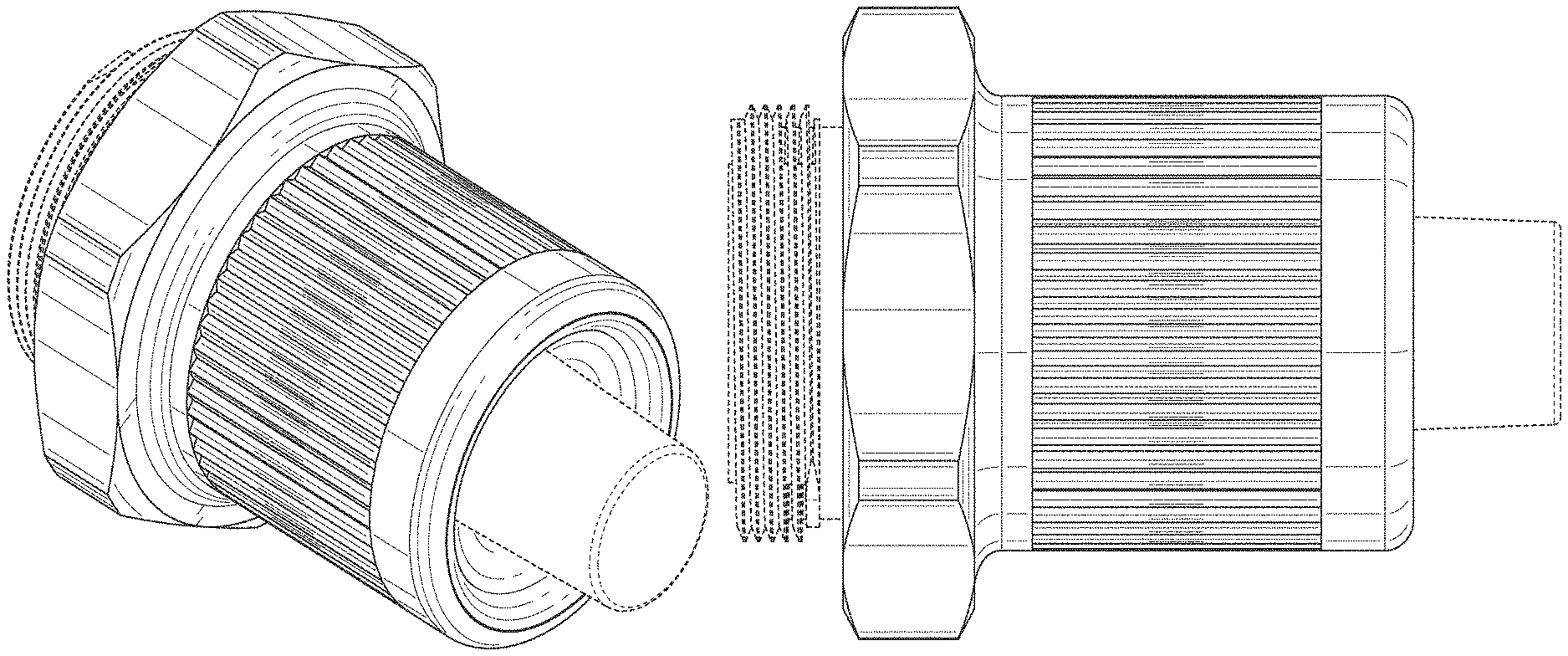
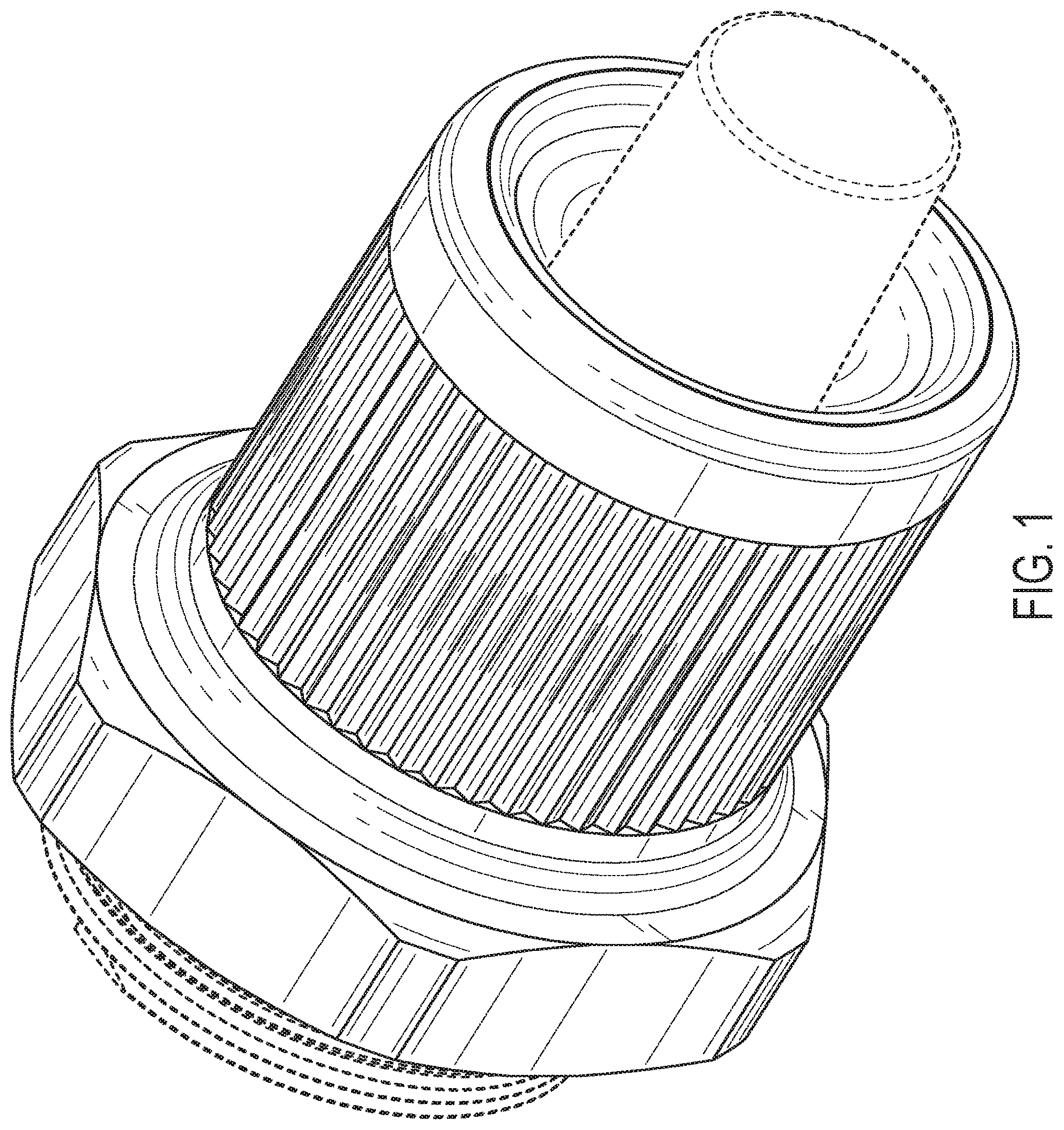
FIG. 1 is a perspective view of a break away rail car power connector nut, showing our new design;
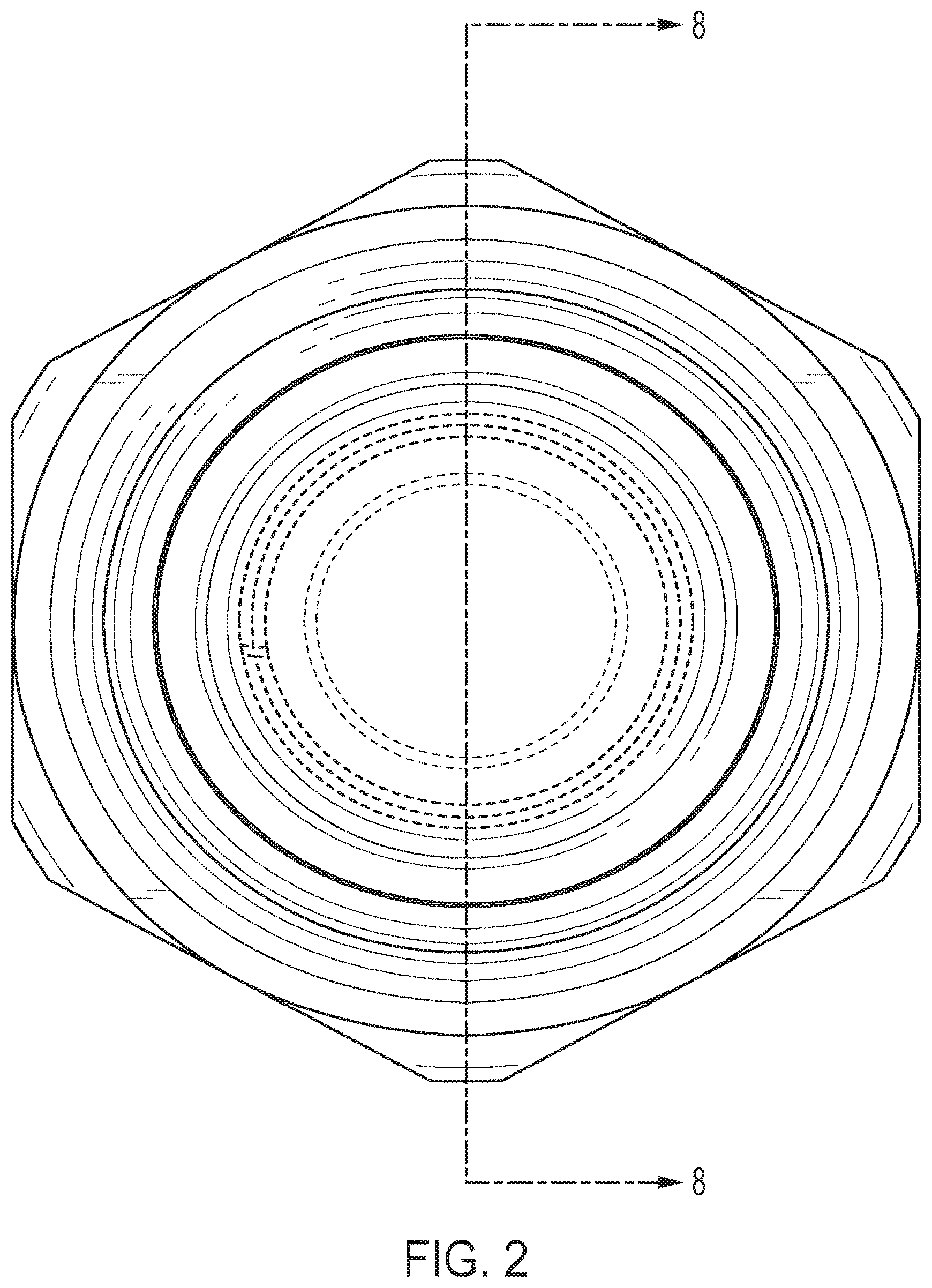
FIG. 2 is a front elevation view thereof;
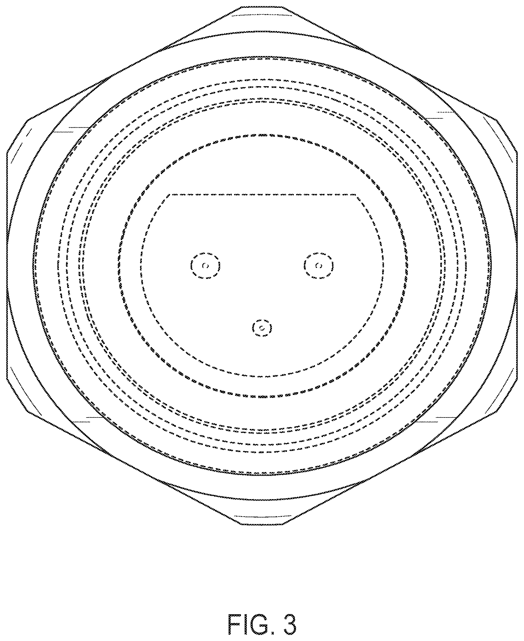
FIG. 3 is a rear elevation view thereof;
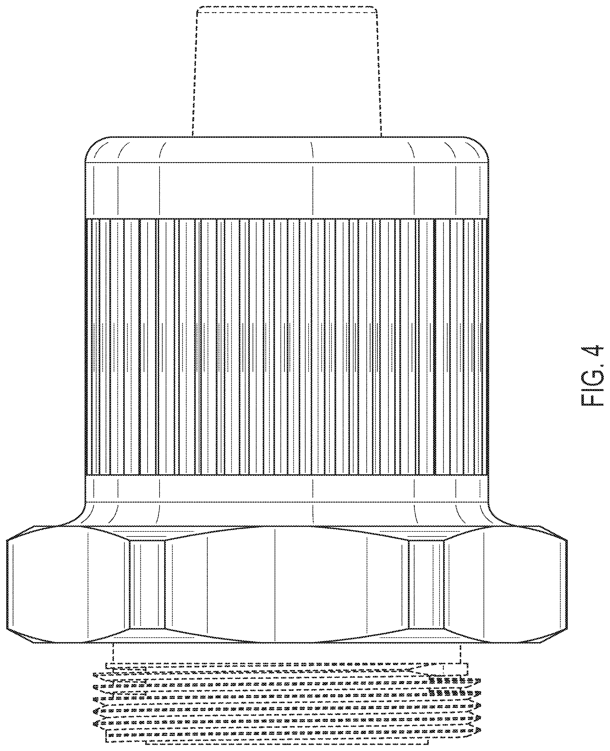
FIG. 4 is a left side elevation view thereof;
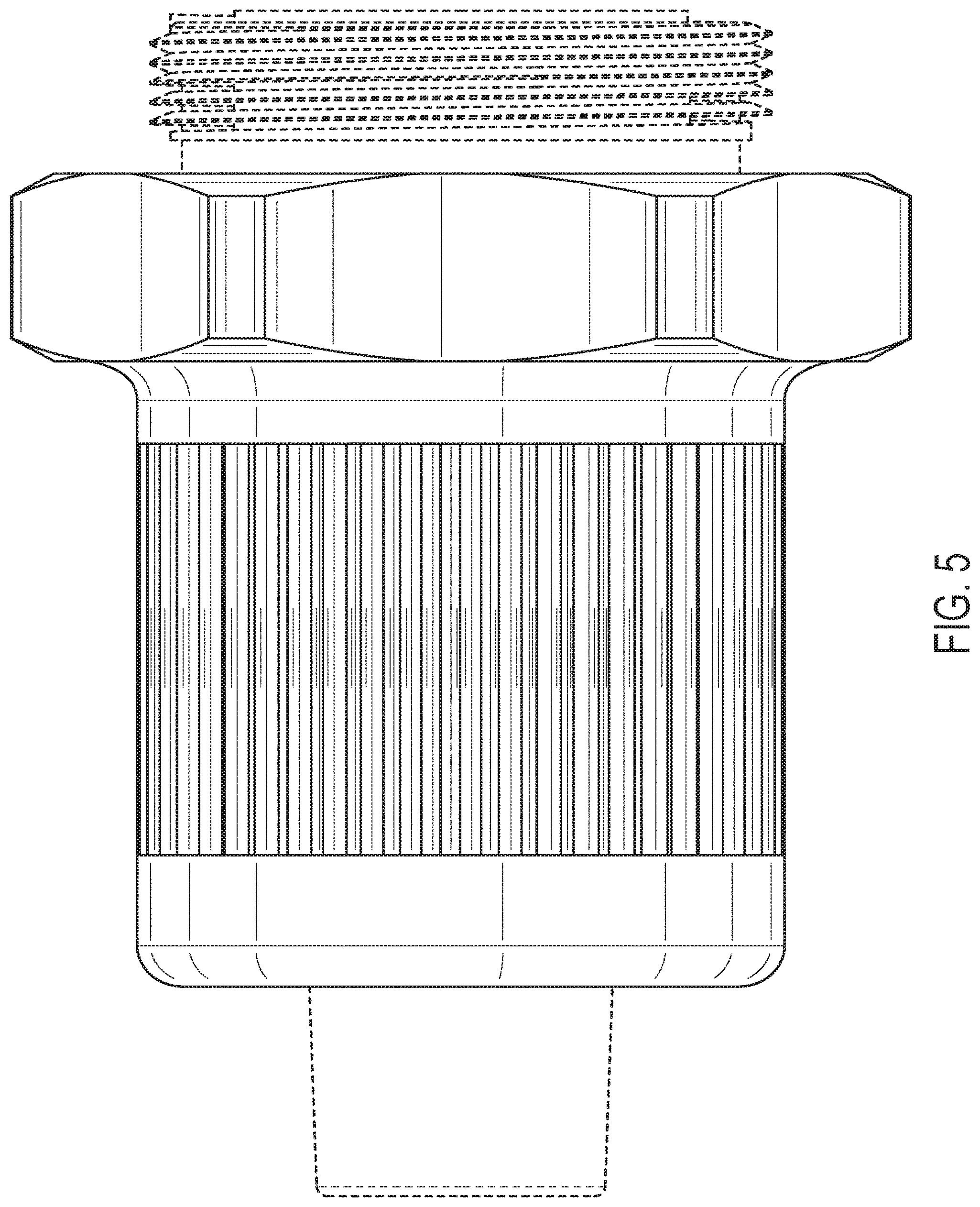
FIG. 5 is a right side elevation view thereof;
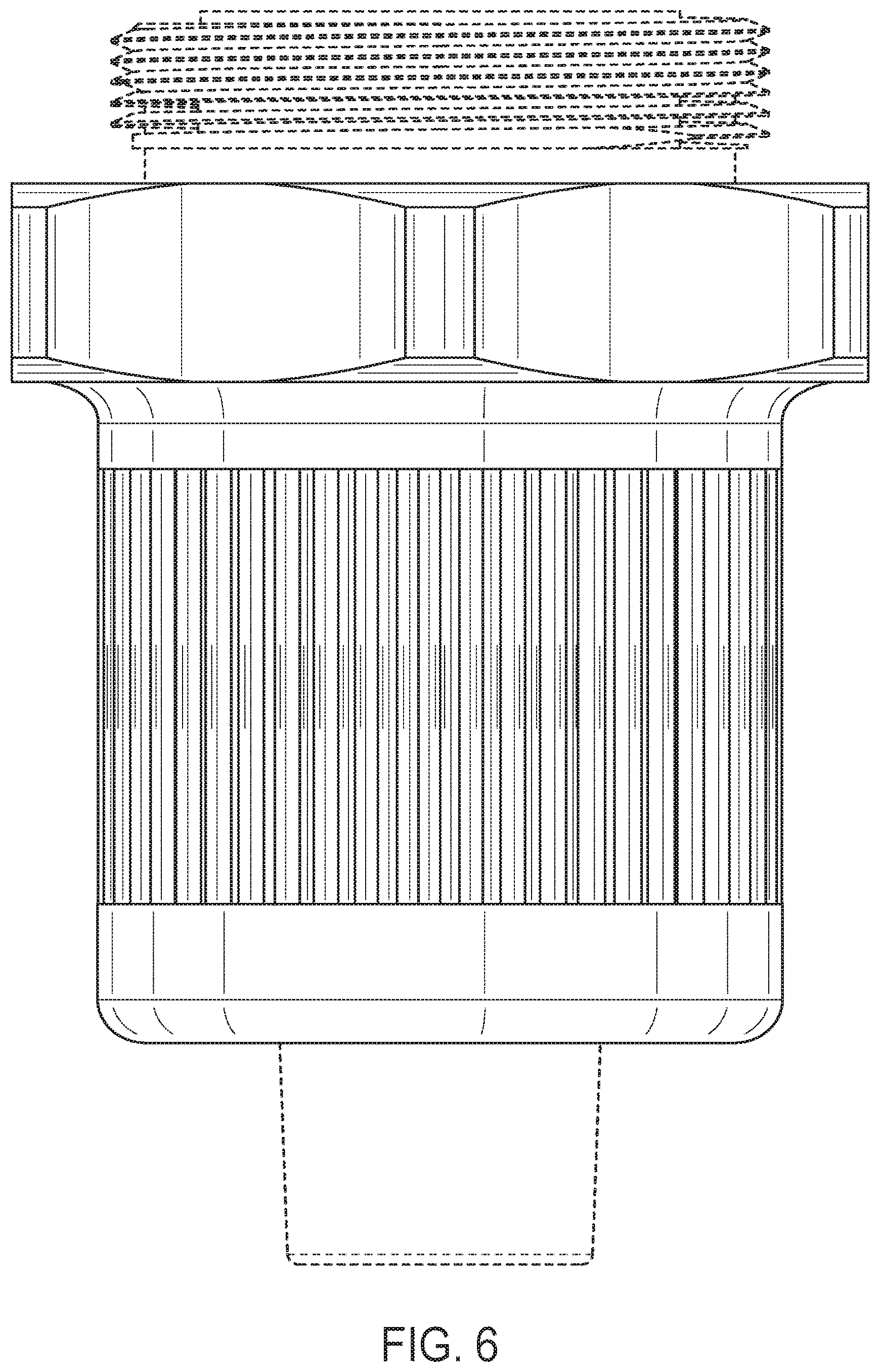
FIG. 6 is a top view thereof;
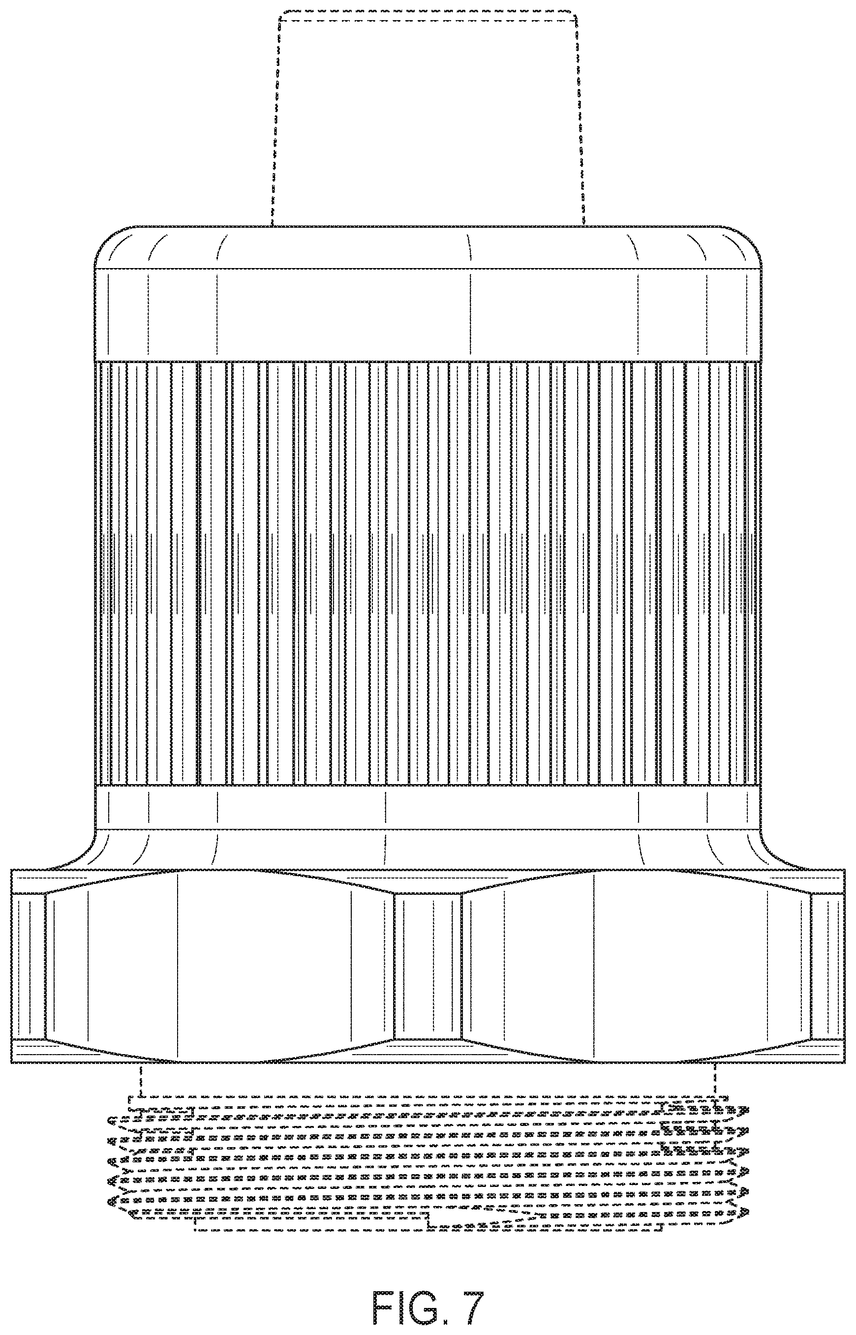
FIG. 7 is a bottom view thereof; and,
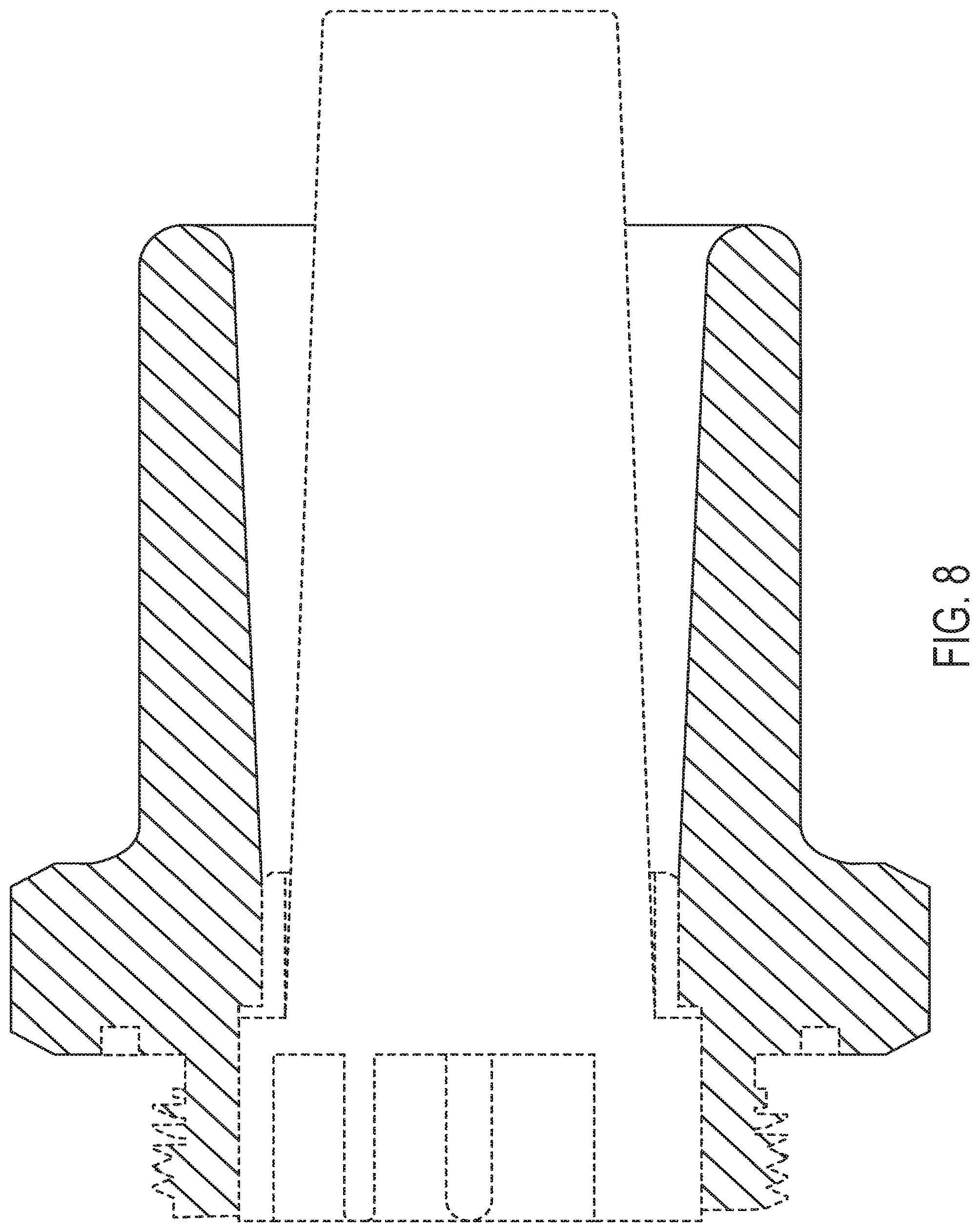
FIG. 8 is a cross-sectional view thereof taken in the direction of line 8-8 shown in FIG. 2.
The broken line showings in FIGS. 1-8 are for the purpose of illustrating environmental structure and form no part of the claimed design.
* * * * *
D00000
D00001
D00002
D00003
D00004
D00005
D00006
D00007
D00008
XML
uspto.report is an independent third-party trademark research tool that is not affiliated, endorsed, or sponsored by the United States Patent and Trademark Office (USPTO) or any other governmental organization. The information provided by uspto.report is based on publicly available data at the time of writing and is intended for informational purposes only.
While we strive to provide accurate and up-to-date information, we do not guarantee the accuracy, completeness, reliability, or suitability of the information displayed on this site. The use of this site is at your own risk. Any reliance you place on such information is therefore strictly at your own risk.
All official trademark data, including owner information, should be verified by visiting the official USPTO website at www.uspto.gov. This site is not intended to replace professional legal advice and should not be used as a substitute for consulting with a legal professional who is knowledgeable about trademark law.