Conductor
Brandt , et al. Nov
U.S. patent number D867,995 [Application Number D/666,775] was granted by the patent office on 2019-11-26 for conductor. This patent grant is currently assigned to EATON INTELLIGENT POWER LIMITED. The grantee listed for this patent is Eaton Intelligent Power Limited. Invention is credited to Douglas Michael Brandt, Tyler Louis Holp, Mark Anthony Janusek, Brad Robert Leccia, Logan Dwight Weigle.


| United States Patent | D867,995 |
| Brandt , et al. | November 26, 2019 |
Conductor
Claims
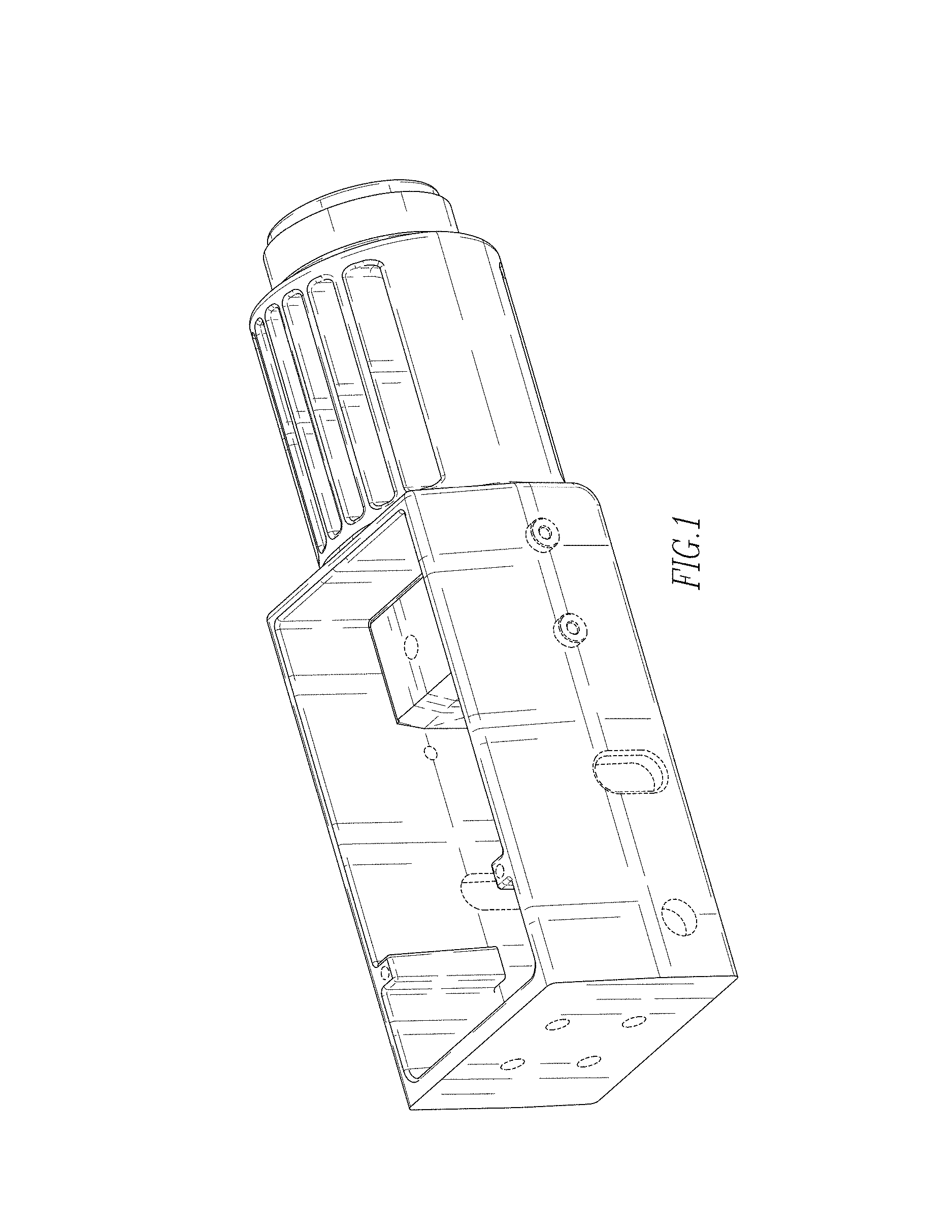
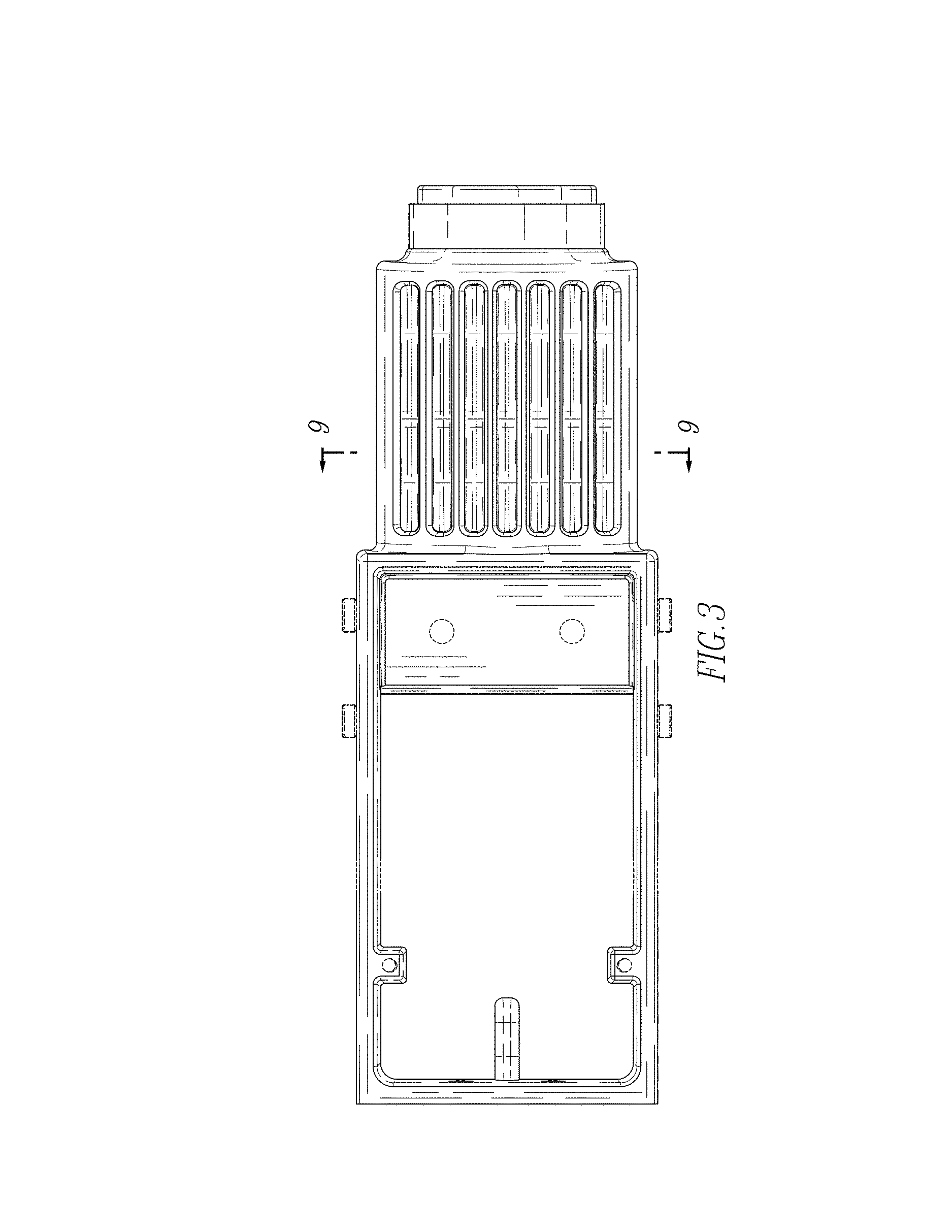
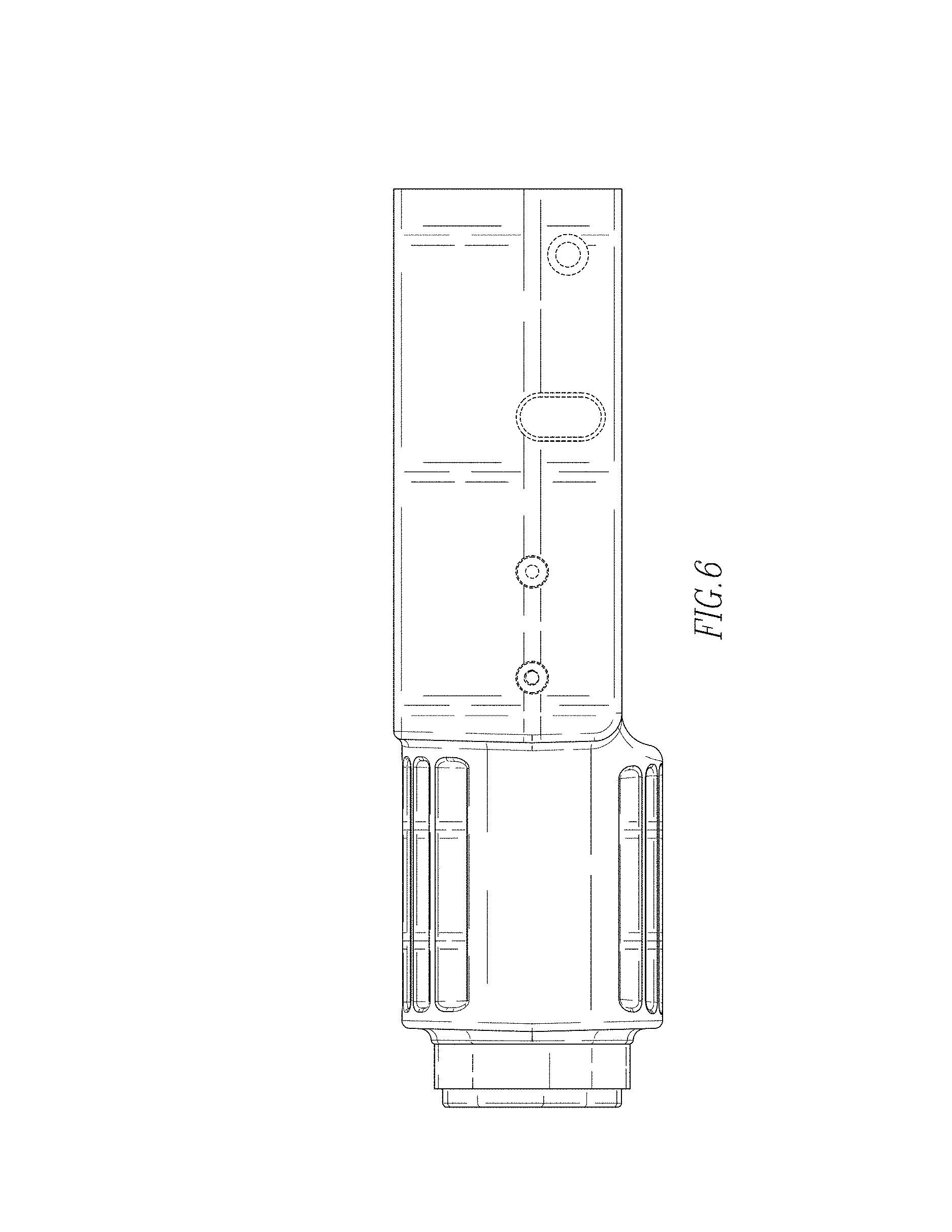
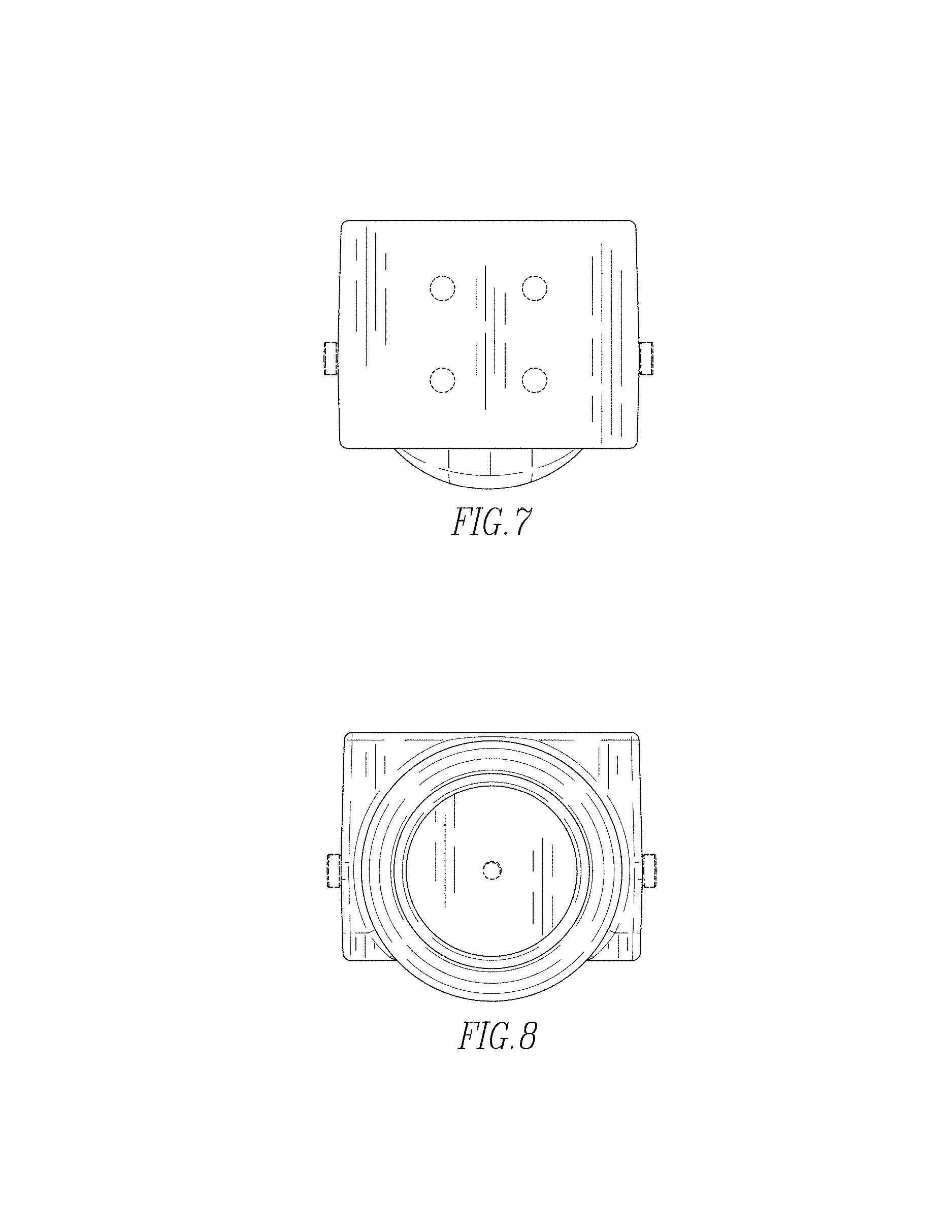
CLAIM The ornamental design for a conductor, as shown and described.
| Inventors: | Brandt; Douglas Michael (Wampum, PA), Janusek; Mark Anthony (Bethel Park, PA), Weigle; Logan Dwight (McKees Rocks, PA), Holp; Tyler Louis (Coraopolis, PA), Leccia; Brad Robert (Bethel Park, PA) | ||||||||||
|---|---|---|---|---|---|---|---|---|---|---|---|
| Applicant: |
|
||||||||||
| Assignee: | EATON INTELLIGENT POWER LIMITED
(Dublin, IE) |
||||||||||
| Appl. No.: | D/666,775 | ||||||||||
| Filed: | October 16, 2018 |
| Current U.S. Class: | D13/133 |
| Current International Class: | 1303 |
| Field of Search: | ;D13/110,112,118,123,133,146-149,154-156,160,173,178,184,199 |
References Cited [Referenced By]
U.S. Patent Documents
| D251491 | April 1979 | Snyder, Jr. |
| D795809 | August 2017 | Brandt |
| 9767978 | September 2017 | Brandt et al. |
| D801930 | November 2017 | Brandt |
| D808347 | January 2018 | Benda |
| D827577 | September 2018 | Brandt |
| D827578 | September 2018 | Brandt |
| D829659 | October 2018 | Brandt |
| D829660 | October 2018 | Brandt |
| D843567 | March 2019 | Gloria Bello |
| 2009/0255905 | October 2009 | Lee |
| 2017/0338071 | November 2017 | Brandt et al. |
Assistant Examiner: Gingrich; Shawn T
Attorney, Agent or Firm: Eckert Seamans Cherin & Mellott, LLC
Description
FIG. 1 is an isometric view of the conductor;
FIG. 2 is another isometric view of the conductor;
FIG. 3 is a top view of the conductor;
FIG. 4 is a bottom view of the conductor;
FIG. 5 is a left view of the conductor;
FIG. 6 is a right view of the conductor;
FIG. 7 is a front view of the conductor;
FIG. 8 is a back view of the conductor; and,
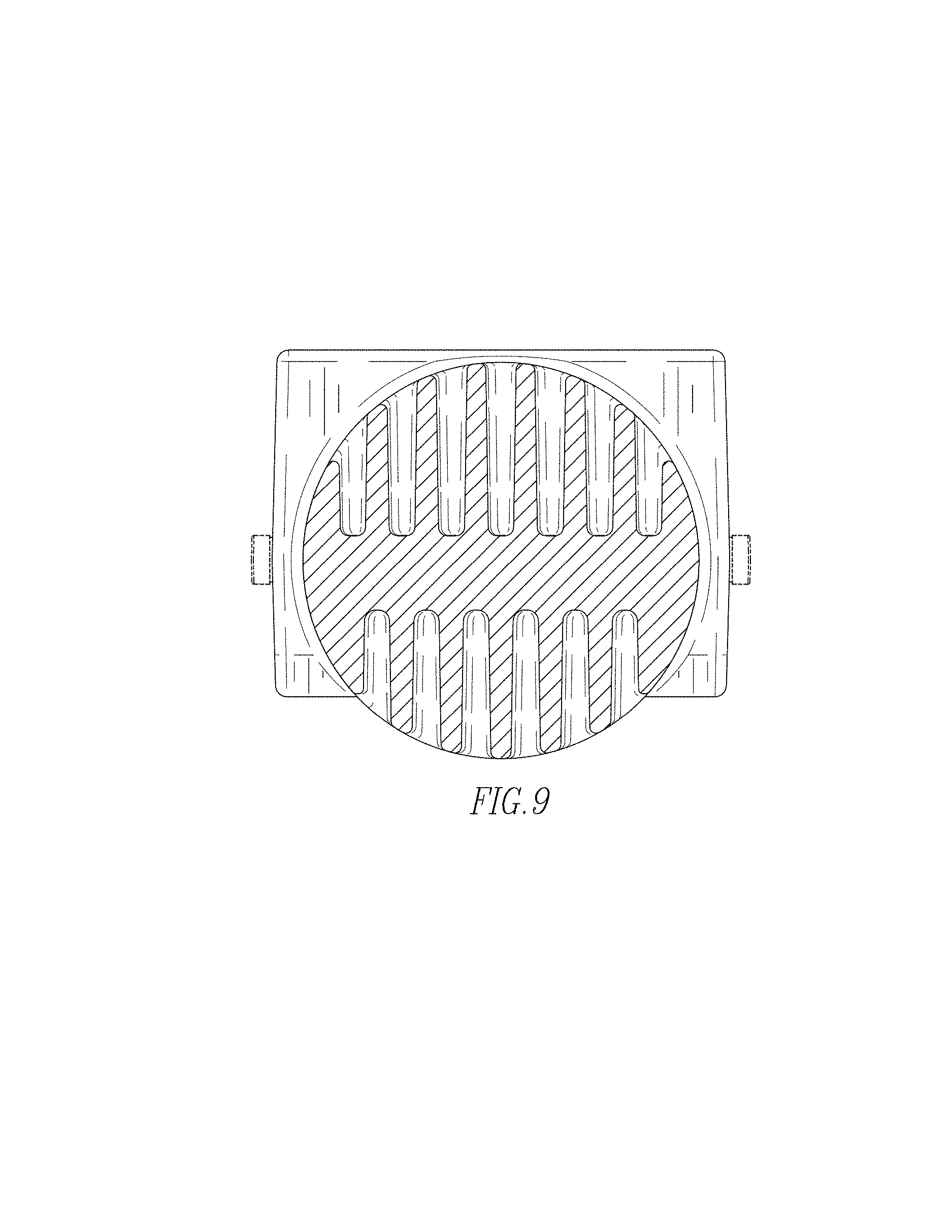
FIG. 9 is a cross-sectional view of the conductor taken along line 9-9 on FIG. 3.
The broken lines in the drawings illustrate portions of the conductor that form no part of the claimed design.
* * * * *
D00000
D00001
D00002
D00003
D00004
D00005
D00006
D00007
D00008
XML
uspto.report is an independent third-party trademark research tool that is not affiliated, endorsed, or sponsored by the United States Patent and Trademark Office (USPTO) or any other governmental organization. The information provided by uspto.report is based on publicly available data at the time of writing and is intended for informational purposes only.
While we strive to provide accurate and up-to-date information, we do not guarantee the accuracy, completeness, reliability, or suitability of the information displayed on this site. The use of this site is at your own risk. Any reliance you place on such information is therefore strictly at your own risk.
All official trademark data, including owner information, should be verified by visiting the official USPTO website at www.uspto.gov. This site is not intended to replace professional legal advice and should not be used as a substitute for consulting with a legal professional who is knowledgeable about trademark law.