Cassette for a digital slide scanner
Suzuki Nov
U.S. patent number D866,555 [Application Number D/621,874] was granted by the patent office on 2019-11-12 for cassette for a digital slide scanner. This patent grant is currently assigned to HAMAMATSU PHOTONICS K.K.. The grantee listed for this patent is HAMAMATSU PHOTONICS K.K.. Invention is credited to Yasumoto Suzuki.


View All Diagrams
| United States Patent | D866,555 |
| Suzuki | November 12, 2019 |
Cassette for a digital slide scanner
Claims
CLAIM The ornamental design for a cassette for a digital slide scanner, as shown and described.
| Inventors: | Suzuki; Yasumoto (Hamamatsu, JP) | ||||||||||
|---|---|---|---|---|---|---|---|---|---|---|---|
| Applicant: |
|
||||||||||
| Assignee: | HAMAMATSU PHOTONICS K.K.
(Hamamatsu-shi, Shizuoka, JP) |
||||||||||
| Appl. No.: | D/621,874 | ||||||||||
| Filed: | October 12, 2017 |
Foreign Application Priority Data
| Apr 13, 2017 [JP] | 2017-007962 | |||
| Current U.S. Class: | D14/432 |
| Current International Class: | 1402 |
| Field of Search: | ;D14/319-321,348,356-368,498,501-503,510 ;720/617-644,646,655-656 ;360/99.19,99.13,98.01 ;361/679.33,679.37 |
References Cited [Referenced By]
U.S. Patent Documents
| D310520 | September 1990 | Bedard |
| 5726435 | March 1998 | Hara et al. |
| D414165 | September 1999 | Klein |
| D578127 | October 2008 | Crisp |
| 7571864 | August 2009 | Kiliccote |
| D686623 | July 2013 | Bennett, Jr. |
| 8573499 | November 2013 | Boyle |
| 8985443 | March 2015 | Boyle |
| D740817 | October 2015 | Ignomirello |
| 9300658 | March 2016 | Sadacharam et al. |
| D755182 | May 2016 | Bassett |
| 9576172 | February 2017 | Huang et al. |
| D808970 | January 2018 | Gessford |
| D830363 | October 2018 | Helms |
| D839271 | January 2019 | King-Murrey |
| 2005/0142940 | June 2005 | Manine |
| 2008/0002853 | January 2008 | Kawabe et al. |
| 2008/0013272 | January 2008 | Bailey |
| 2008/0121688 | May 2008 | Harrop |
| 2008/0301464 | December 2008 | Parkinson |
| 2009/0043783 | February 2009 | Wakasa et al. |
| 2009/0057420 | March 2009 | Onoda et al. |
| 2009/0108057 | April 2009 | Mu et al. |
| 2009/0255992 | October 2009 | Shen |
| 2011/0043858 | February 2011 | Jetter |
| 2012/0104105 | May 2012 | Nemet et al. |
| 2012/0197660 | August 2012 | Prodanovich |
| 2012/0209688 | August 2012 | Lamothe et al. |
| 2012/0267440 | October 2012 | Nakaya et al. |
| 2012/0323699 | December 2012 | Phillips |
| 2013/0026241 | January 2013 | Sakahashi et al. |
| 2013/0043302 | February 2013 | Powlen et al. |
| 2013/0087609 | April 2013 | Nichol et al. |
| 2013/0126598 | May 2013 | Beadles et al. |
| 2013/0146658 | June 2013 | Guerra |
| 2013/0166441 | June 2013 | Kobylkin et al. |
| 2013/0221114 | August 2013 | Myers et al. |
| 2013/0320099 | December 2013 | Acton et al. |
| 2013/0341417 | December 2013 | Argue et al. |
| 2014/0070012 | March 2014 | Hunt et al. |
| 2014/0100973 | April 2014 | Brown et al. |
| 2014/0108606 | April 2014 | Beadles |
| 2014/0110468 | April 2014 | Kandregula |
| 2014/0110486 | April 2014 | Nemet |
| 2014/0117100 | May 2014 | Black et al. |
| 2014/0117101 | May 2014 | Cok |
| 2014/0144996 | May 2014 | Friedman et al. |
| 2014/0149285 | May 2014 | De et al. |
| 2014/0224888 | August 2014 | Bomer et al. |
| 2014/0224889 | August 2014 | Key |
| 2014/0263667 | September 2014 | Mege |
| 2014/0263674 | September 2014 | Cerveny |
| 2014/0263675 | September 2014 | Beadles |
| 2014/0281855 | September 2014 | Bhatnagar |
| 2015/0008257 | January 2015 | Beadles |
| 2015/0161496 | June 2015 | Rodriguez et al. |
| 2015/0199601 | July 2015 | Bienek |
| 2015/0213734 | July 2015 | Glickman |
| 2015/0229603 | August 2015 | Chor |
| 2015/0269466 | September 2015 | Inotay et al. |
| 2015/0269469 | September 2015 | Sharma et al. |
| 2015/0363683 | December 2015 | Polzoni |
| 2016/0086072 | March 2016 | Castillo |
| 2016/0140428 | May 2016 | Kamitani et al. |
| 2016/0155033 | June 2016 | Nakano et al. |
| 2016/0180131 | June 2016 | Seo et al. |
| 2017/0235977 | August 2017 | Nadabar et al. |
| 2018/0025263 | January 2018 | Toyoizumi et al. |
| 2018/0137323 | May 2018 | Jiang et al. |
| 2018/0157813 | June 2018 | Rodrigs et al. |
Attorney, Agent or Firm: Drinker Biddle & Reath LLP
Description
FIG. 1 is a front view of a cassette for a digital slide scanner of the present invention.
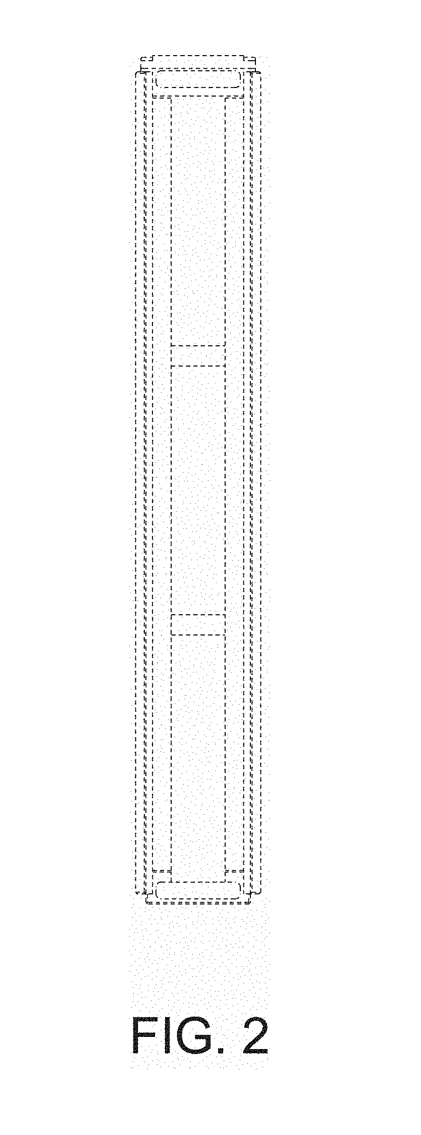
FIG. 2 is a rear view thereof.
FIG. 3 is a top plan view thereof.
FIG. 4 is a bottom view thereof.
FIG. 5 is a right side view thereof.
FIG. 6 is a left side view thereof.
FIG. 7 is a perspective view thereof.
FIG. 8 is an enlarged view showing a portion of FIG. 1 defined by the line 8-8.
FIG. 9 is an enlarged view showing a portion of FIG. 5 defined by the line 9-9.
FIG. 10 is an enlarged view showing a portion of FIG. 6 defined by the line 10-10.
FIG. 11 is an enlarged view showing a portion of FIG. 7 defined by the line 11-11.
FIG. 12 is an enlarged cross-sectional view taken along the line 12-12 in FIG. 8.
FIG. 13 is an enlarged cross-sectional view taken along the line 13-13 in FIG. 9; and,
FIG. 14 is an enlarged cross-sectional view taken along the line 14-14 in FIG. 9.
The features shown in broken lines depict environmental subject matter only and form no part of the claimed design.
The alternating long and short dashed lines indicate bounds of the claimed design and form no part thereof.
* * * * *
D00000
D00001
D00002
D00003
D00004
D00005
D00006
D00007
D00008
D00009
D00010
D00011
D00012

D00013

D00014

XML
uspto.report is an independent third-party trademark research tool that is not affiliated, endorsed, or sponsored by the United States Patent and Trademark Office (USPTO) or any other governmental organization. The information provided by uspto.report is based on publicly available data at the time of writing and is intended for informational purposes only.
While we strive to provide accurate and up-to-date information, we do not guarantee the accuracy, completeness, reliability, or suitability of the information displayed on this site. The use of this site is at your own risk. Any reliance you place on such information is therefore strictly at your own risk.
All official trademark data, including owner information, should be verified by visiting the official USPTO website at www.uspto.gov. This site is not intended to replace professional legal advice and should not be used as a substitute for consulting with a legal professional who is knowledgeable about trademark law.