Oral care implement handle
Wainless , et al. Nov
U.S. patent number D866,194 [Application Number D/660,392] was granted by the patent office on 2019-11-12 for oral care implement handle. This patent grant is currently assigned to Colgate-Palmolive Company. The grantee listed for this patent is Colgate-Palmolive Company. Invention is credited to Douglas Henderson, Douglas Hohlbein, Jiunnhaur Lim, Daniel Wainless, Jiantao Wang, Pei Zhou.

| United States Patent | D866,194 |
| Wainless , et al. | November 12, 2019 |
Oral care implement handle
Claims
CLAIM The ornamental design for an oral care implement handle, as shown and described.
| Inventors: | Wainless; Daniel (New Brunswick, NJ), Hohlbein; Douglas (Hopewell, NJ), Henderson; Douglas (Basking Ridge, NJ), Lim; Jiunnhaur (Shanghai, CN), Wang; Jiantao (Shanghai, CN), Zhou; Pei (Shanghai, CN) | ||||||||||
|---|---|---|---|---|---|---|---|---|---|---|---|
| Applicant: |
|
||||||||||
| Assignee: | Colgate-Palmolive Company (New
York, NY) |
||||||||||
| Appl. No.: | D/660,392 | ||||||||||
| Filed: | August 21, 2018 |
Related U.S. Patent Documents
| Application Number | Filing Date | Patent Number | Issue Date | ||
|---|---|---|---|---|---|
| 29585611 | Nov 28, 2016 | D828035 | |||
| Current U.S. Class: | D4/138; D4/104 |
| Current International Class: | 0402 |
| Field of Search: | ;D4/100,101,102,104,108,112,138 ;D24/119,152,176 |
References Cited [Referenced By]
U.S. Patent Documents
| 5875510 | March 1999 | Lamond et al. |
| 6145152 | November 2000 | Ward |
| D457326 | May 2002 | Winkler |
| 6546585 | April 2003 | Blaustein et al. |
| D549459 | August 2007 | Crossman |
| D715560 | October 2014 | Li |
| D775470 | January 2017 | Xi |
| D780457 | March 2017 | Jimenez |
| D798062 | September 2017 | Bauernfeind |
| D799836 | October 2017 | Bauernfeind |
| D814195 | April 2018 | Sikora |
| D823000 | July 2018 | Wainless |
| D828035 | September 2018 | Wainless |
| D833756 | November 2018 | Hielscher |
| 2017/0216004 | August 2017 | Okai |
| 003862416-0015 | Jul 2017 | EM | |||
Assistant Examiner: Mlinarcik; Jasmine
Description
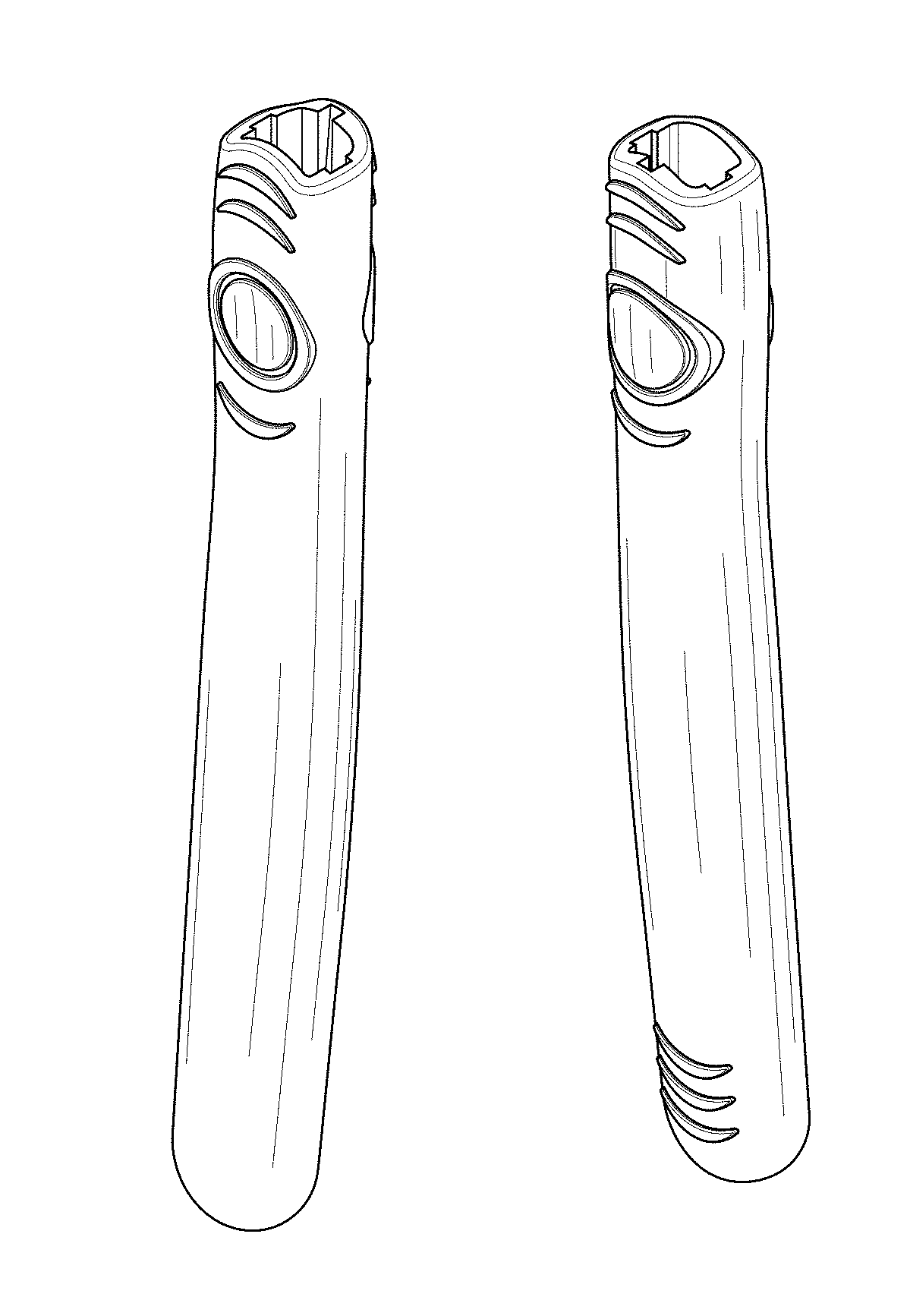
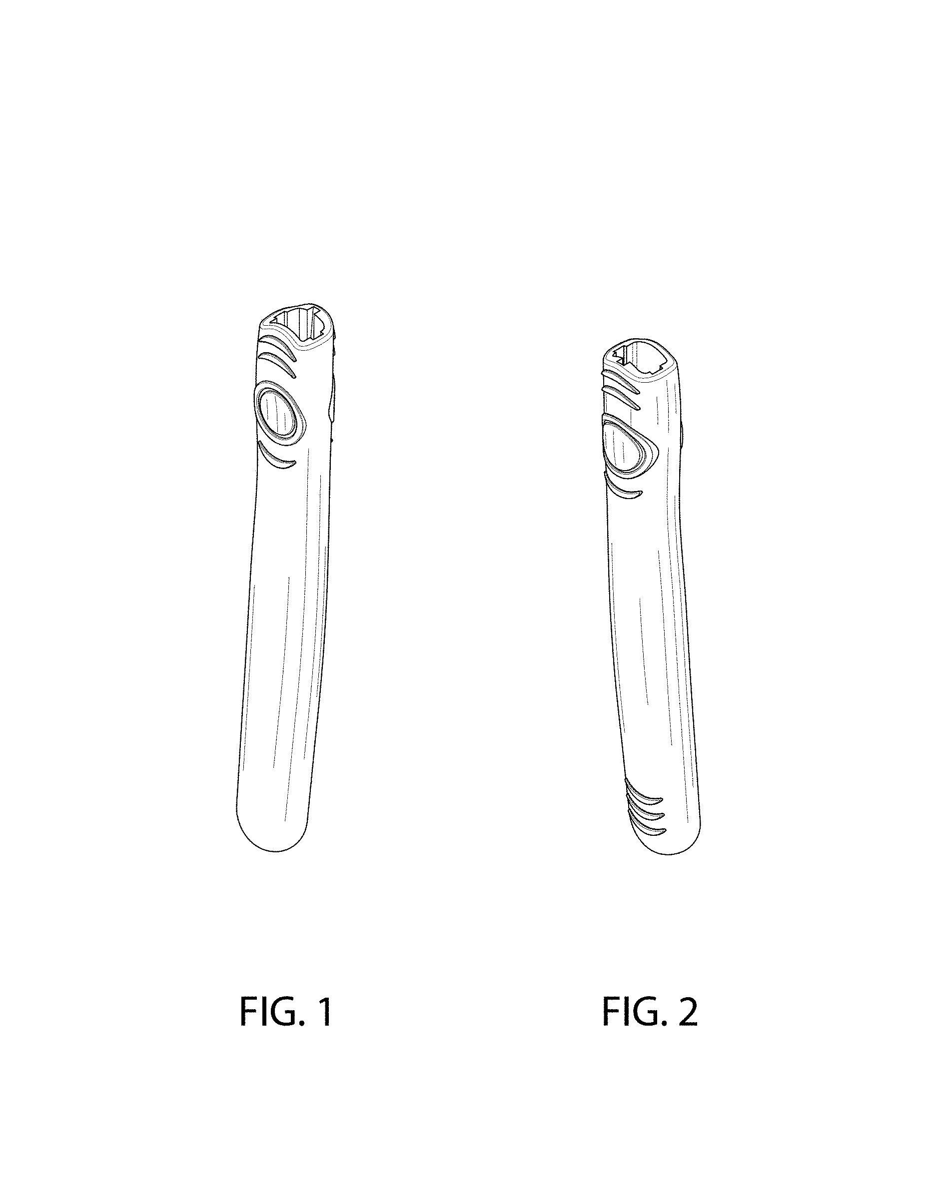
FIG. 1 is a front right perspective view of an oral care implement handle according to the new design;
FIG. 2 is a rear left perspective view thereof;
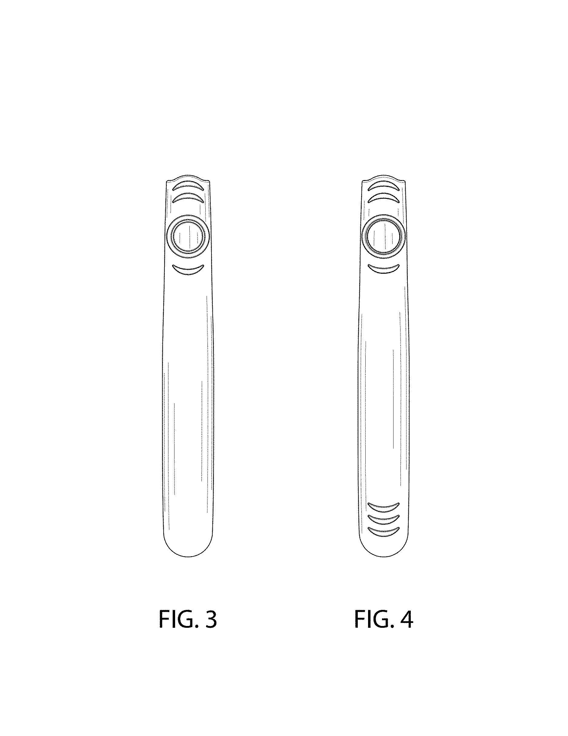
FIG. 3 is a front view thereof;
FIG. 4 is a rear view thereof;
FIG. 5 is a right side view thereof,
FIG. 6 is a left side view thereof;
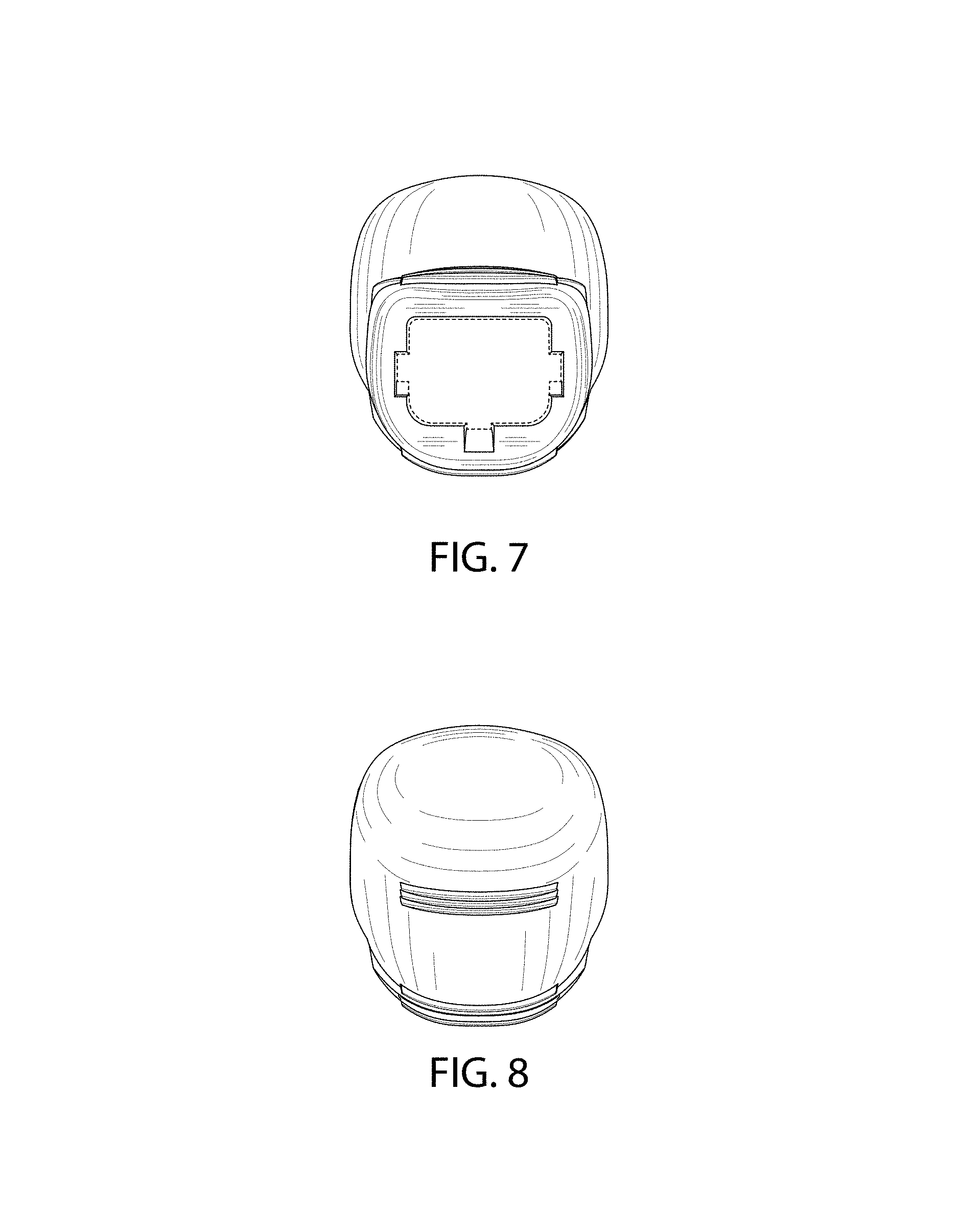
FIG. 7 is an enlarged top view thereof; and,
FIG. 8 is an enlarged bottom view thereof.
The broken line shown in FIG. 7 defines the bounds of the claimed design and forms no part thereof.
* * * * *
D00000
D00001
D00002
D00003
D00004
XML
uspto.report is an independent third-party trademark research tool that is not affiliated, endorsed, or sponsored by the United States Patent and Trademark Office (USPTO) or any other governmental organization. The information provided by uspto.report is based on publicly available data at the time of writing and is intended for informational purposes only.
While we strive to provide accurate and up-to-date information, we do not guarantee the accuracy, completeness, reliability, or suitability of the information displayed on this site. The use of this site is at your own risk. Any reliance you place on such information is therefore strictly at your own risk.
All official trademark data, including owner information, should be verified by visiting the official USPTO website at www.uspto.gov. This site is not intended to replace professional legal advice and should not be used as a substitute for consulting with a legal professional who is knowledgeable about trademark law.